A Residential Inverter Has More Than One Cooling Problem
A home energy-storage inverter may look quiet and simple from the outside, but its cooling duty changes sharply between a sunny afternoon, an evening discharge and a low-load night standby state.
The fan selection question is therefore not simply which model has the highest free-air CFM. The design team must decide how much heat is released by the inverter switches, charger, magnetics and control electronics, where that heat leaves the enclosure, and what the installed air path does to pressure, noise and service life. A fan that looks acceptable in a laboratory can become a weak point when a grille, filter, heat sink, cable bundle or wall clearance is added.
Residential equipment also has a different acoustic context from a factory cabinet. A tonal peak during a quiet evening charge can be more objectionable than a higher broadband level during daylight. At the same time, the fan still has to protect the power stage when the outside air is hot, the cabinet is exposed to sun or the filter has accumulated dust. This is a control and validation problem as much as a component-selection problem.
This article gives thermal engineers, mechanical designers and procurement teams a repeatable method for reviewing the fan-assisted part of a residential ESS inverter. The examples are engineering estimates, not a claim about a particular customer's system. Replace them with measured heat loss, pressure, temperature, acoustic and environmental data before production release.
Start With the Operating Envelope, Not the Fan Catalogue
A useful design review begins with the states that the residential system actually enters during a week of operation.
At solar peak, the inverter may be processing high input power while the outdoor temperature is also elevated. During evening discharge, the power direction changes and the heat balance may shift between switching devices, magnetics and the charger. During backup operation, the equipment can remain at a meaningful load even when the building is quiet. At night, the requested fan speed may be low, but a small control loss or a warm internal hotspot can still require stable airflow.
Write the envelope as a matrix: ambient temperature, solar exposure, charge or discharge power, expected duration, cabinet inlet temperature, fan command, measured RPM, airflow or differential pressure, hottest component temperature and sound level. Include the transition into each state. Thermal failures often occur during a ramp, restart or recovery event rather than after a long steady run.
Public residential ESS documentation commonly specifies operating temperature ranges and clearances, but these values describe the complete product and installation boundary. They do not automatically provide the fan's installed duty. The inverter manufacturer still needs to map its own heat sources, enclosure resistance, control limits and service conditions.
A Heat-Loss Estimate That Tells You What to Measure
A first-pass heat balance helps the team decide whether a passive surface, a fan-assisted path or a different thermal architecture deserves the next test.
Consider an illustrative 8 kW inverter operating at 97 percent efficiency. The conversion loss is approximately 8,000 x (1 - 0.97) = 240 W. Add an estimated 25 W for control electronics, magnetics and auxiliary losses and the air-cooled bay may need to reject roughly 265 W. This is not a product claim; it is a screening calculation that tells the test team what scale of airflow to investigate.
If the design allows an average air temperature rise of 12 K, a simple air-side estimate is Q = P/(rho x cp x delta T). Using rho x cp of approximately 1,200 J/(m3 K), Q = 265/14,400 = 0.0184 m3/s, or about 39 CFM. The actual required fan flow can be higher because the hottest component may need a smaller local temperature rise, and because recirculation means the inlet air may already be warmer than room ambient.
Now add pressure. Suppose the grille, heat sink, dust screen and outlet clearance require 90 Pa at this flow. The candidate must deliver approximately 39 CFM at 90 Pa, not 39 CFM at zero pressure. If the filter later adds another 35 Pa, the operating point moves again. This is why the design record should retain the pressure-flow measurement and not only the command percentage or nameplate RPM.
| Input | Example | What it tells the team |
|---|---|---|
| Inverter loss | 8 kW at 97% = 240 W | Start with the power-stage heat budget |
| Auxiliary loss | 25 W estimate | Include controls, magnetics and local hot spots |
| Allowable average rise | 12 K | Sets a first airflow target |
| Estimated air flow | about 39 CFM | Screening value before enclosure testing |
| Installed resistance | 90 Pa plus filter drift | Select the fan on the loaded P-Q point |
The Animated Duty Model: Quiet Night Versus Hot Loaded Day
The same fan command can mean different thermal results when the inlet temperature and system resistance change.
In the night state, the controller may request a low PWM command. If the air path is clean and the heat load is small, sparse blue flow can remove the local loss without creating unnecessary noise. The design still needs a minimum stable speed, a restart rule and a feedback check. A fan that stops reliably at low command but cannot restart after a warm soak is not a controlled quiet state.
In the hot daytime state, the ambient air is warmer and the filter or grille may be more restrictive. The same RPM does not prove the same airflow. The operating point can move left on the fan curve, while the required heat rejection rises. A red thermal zone or rising differential pressure should therefore trigger a controlled speed increase, a service alarm or a system derating decision, depending on the product's safety and control architecture.
The figure below is qualitative. It is intended to make the test sequence visible, not to replace a CFD model, P-Q curve or acoustic measurement. Engineers should record the actual fan feedback, pressure and temperature at both states and compare the result to the acceptance limits.

Night-Time Noise Is a Control and Mounting Problem
A low sound-pressure number is not enough if a tonal peak, panel resonance or repeated speed hunting is audible beside a home.
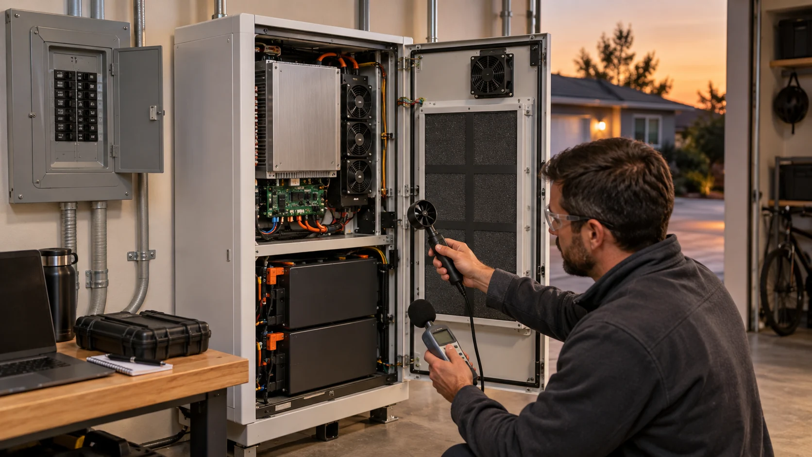
Residential fan noise should be reviewed in at least four states: startup, stable low speed, thermal recovery at high speed and stop or restart. Record overall sound pressure and listen to the spectrum for blade-pass or commutation tones. The measurement position should represent the installation, because a thin wall, cover or mounting bracket can amplify vibration even when the fan itself is quiet on an open bench.
Temperature control can create an avoidable acoustic problem. If the threshold is too narrow, the fan repeatedly crosses it, ramps up, ramps down and crosses it again. This hunting is easy to miss in a short bench test but becomes obvious during a long evening charge. Use hysteresis, a controlled ramp and a minimum dwell time, then verify that the hottest component still meets its limit during the quiet state.
A custom fan review should therefore include mounting isolation, cable routing, PWM frequency, minimum duty, FG behavior and the acoustic acceptance location. A quieter fan with insufficient static pressure is not a solution. The air path and the fan blade, motor and controller need to be treated as one acoustic system.
High Ambient, Solar Exposure and Derating Margin
The most important fan margin may be consumed before the fan starts because the cabinet intake is already hotter than the weather report.
An outside-wall or garage installation can see a different inlet temperature from the local weather station. Dark panels, nearby walls and exhaust recirculation can raise the air entering the inverter. Measure the air at the actual inlet and log it with the component temperature. If the fan is placed behind a narrow cover, verify that the hot exhaust cannot return through the inlet during wind or a changing sun angle.
A useful screening example is a 10 K temperature-margin loss caused by hot inlet air. If the power-stage temperature limit was originally met with 15 K of margin, the effective margin is now only 5 K before dust, voltage variation or component aging is considered. The answer may be a larger fan, a better duct, a different outlet, a heat spreader or an earlier controlled derating. It is not automatically a higher RPM command.
Public documentation for residential batteries often makes clear that the product is temperature-dependent and that clearances matter. Use those documents as installation constraints, then create an inverter-specific acceptance matrix with hot ambient, maximum load, low voltage, filter condition and recovery time.
Filter Loading, IP Protection and Serviceability
A residential inverter may need dust protection, rain resistance or a serviceable filter, but every added layer changes the fan duty.
A grille or filter can protect the power electronics from dust and insects, yet it also adds pressure loss. Test the clean condition and the intended service-limit condition. The service limit should be linked to differential pressure or an inspection interval, not an arbitrary fan command. If the system has no practical filter service, the air path may need more pressure margin, a different inlet strategy or a sealed thermal interface.
Ingress protection is not achieved by selecting a fan with an attractive label alone. The enclosure, gasket, cable exit, drain path, grille and service door all participate. A fan supplier can provide a construction and environmental option for the fan, but the complete product still needs its own ingress and safety validation. Do not imply that a fan IP rating certifies the residential ESS.
Serviceability is a design variable. Ask whether a technician can remove the fan without opening a hazardous compartment, whether the connector is keyed and accessible, whether the fan can be replaced without disturbing the heat sink and whether the controller detects a missing or locked rotor. These questions should be answered before the production sample is frozen.
| Check | Record | Pass condition |
|---|---|---|
| Clean path | Pressure and airflow at nominal voltage | Required flow at the expected clean resistance |
| Service-limit path | Filter differential pressure or equivalent restriction | Temperature remains within the agreed limit |
| Hot inlet | Inlet temperature at the fan face | No recirculation-driven loss of margin |
| Low-speed state | PWM, FG, current and sound spectrum | Stable airflow without hunting or stall |
| Fault state | Locked rotor or missing feedback response | Defined safe response and service indication |
PWM, FG and Fault Logic for Low-Load Operation
The fan interface should be specified as a behavior over temperature and load, not as a connector pinout alone.
A residential inverter may need a low acoustic state for many hours, but the fan must still start after a long stop, tolerate the supply range and provide a trustworthy feedback signal. Define the minimum start command, minimum running command, restart delay, acceleration ramp, FG pulse interpretation and locked-rotor response. If the controller assumes a feedback pulse at a command that cannot physically sustain the rotor, the diagnosis becomes ambiguous.
PWM frequency and duty behavior can affect audible noise, motor heating and the usable speed range. Test the actual controller and wiring harness, including connector resistance and cable length. A fan that behaves correctly on a laboratory supply can behave differently when the inverter's supply ripple, EMI filter or protection circuit is included.
The final logic should distinguish thermal control from safety response. A temperature loop may request more speed, while an FG/RD fault should create a service event or safe system response according to the inverter manufacturer's design. The fan can provide signals; it does not replace the product's protection, isolation or battery-management functions.
An Anonymized European Residential ESS Validation Example
A useful case format shows the engineering sequence without pretending that an unapproved customer result is a published product specification.
In an anonymized European residential-storage development, the inverter team wanted quiet evening operation but saw the power-stage temperature rise faster than expected during a warm-weather discharge. The first prototype used a catalogue fan at a low command. Its free-air rating looked sufficient, yet the installed grille, heat sink and cable path moved the operating point to a lower-flow region. The team also observed a tonal peak when the controller repeatedly crossed its temperature threshold.
MEGA Tech's engineering review would start with the customer's sample, heat-loss states, fan cut-out, actual obstruction and measured pressure. A higher-static-pressure axial sample and a compact centrifugal option can then be compared at the same envelope and voltage. The control review would set a stable minimum speed, add hysteresis, verify FG behavior and test the hot inlet condition. The customer, not the fan supplier, remains responsible for the complete inverter and installation approval.
The transferable lesson is not that one fan size solves every home-storage cabinet. It is that the fan, grille, heat sink and firmware must be validated as an installed assembly. A small first build can expose noise, pressure, connector and service issues before the enclosure tooling and production BOM are locked. The final result should be reported with the measured duty, test conditions and limits, not with a generic max-CFM headline.
How MEGA Tech Supports a Custom Residential Inverter Fan
MEGA Tech is a custom cooling-fan manufacturer. We help product teams turn a real cabinet constraint into a sample that can be measured on the customer's unit.
We can review a customer sample and compare custom DC or EC fans, axial fans and backward-curved centrifugal blowers according to the installed operating condition rather than a part number alone. The review can include fan envelope, pressure-flow behavior, PWM response, FG/RD feedback, connector and cable exit, acoustic target, environmental construction and a small first build for evaluation. Replacement work can also begin from an existing fan part number, but same dimensions alone do not prove equivalence.
For an efficient first review, send heat loss by operating state, target airflow and static pressure at that airflow, ambient and altitude basis, voltage tolerance, control interface, connector, available envelope, mounting direction, noise target, expected life, dust or moisture exposure and quantity. Photos or a simple section drawing of the grille, heat sink, duct and outlet are often more useful than a free-air CFM number.
Our boundary is clear: MEGA Tech does not certify the complete residential ESS, battery safety function, liquid loop, inverter controller, fire strategy or regional installation approval. We support the fan and air-path portion, provide engineering samples and help the product team validate the result on the real assembly.
Engineer FAQ: Residential ESS Inverter Fan Validation
Use these questions during a design review, supplier comparison or prototype sign-off.
Q: Does a larger battery require a larger fan? A: Not necessarily. Fan duty follows inverter and auxiliary heat loss, allowable temperature rise and installed resistance, not kWh capacity alone.
Q: Can I use the same RPM target in summer and winter? A: RPM is not airflow. Inlet temperature, filter condition and system resistance can change the operating point, so record airflow or differential pressure and component temperature.
Q: Is a high free-air CFM fan enough? A: No. The candidate must meet the required flow at the installed pressure, including the service-limit filter or grille condition.
Q: When is a centrifugal blower preferable? A: When the path has a sharp turn, narrow duct, heat sink restriction or higher pressure requirement. Compare the installed P-Q point and outlet geometry.
Q: How should residential noise be specified? A: Define the measurement position, overall sound level, tonal acceptance, startup behavior, steady low-speed behavior and speed-ramp behavior on the real cabinet.
Q: What should the supplier receive? A: Heat load, ambient, airflow path, pressure estimate, fan envelope, voltage, PWM/FG/RD interface, noise target, environmental exposure, life assumption and quantity.
Q: Can a fan run slowly all night? A: Only after minimum speed, restart, feedback, condensation and low-load thermal stability have been validated on the product.
Q: Does an IP-rated fan certify the enclosure? A: No. The complete enclosure, gasket, cable exit, service door, drain and installation must be assessed by the product owner.
Questions for a Residential ESS Design Review
A short record of decisions makes the fan sample easier to compare, reproduce and release.
- Which components create heat in each solar peak, charge, discharge, backup and standby state?
- What is the actual inlet temperature at the fan face under sun, wall and exhaust-recirculation conditions?
- What pressure do the grille, filter, heat sink, cable bundle, duct and outlet clearance create?
- Where does the selected fan operate on its P-Q curve in clean and service-limit conditions?
- What is the minimum stable PWM command, restart rule and FG/RD interpretation?
- Has the installed assembly been measured for overall sound, tonal peaks, vibration and speed hunting?
- What is the response to a locked rotor, missing feedback or a blocked path?
- Can a technician replace the fan without disturbing hazardous or sealed parts of the product?
- Which requirement belongs to the fan supplier and which belongs to the complete ESS integrator?
- What exact data will be recorded before the production BOM is released?