A Controller Command Is Not a Fan Condition
A cabinet can request the right speed while the fan sees the wrong voltage, noise or nothing at all on one of its four circuits.
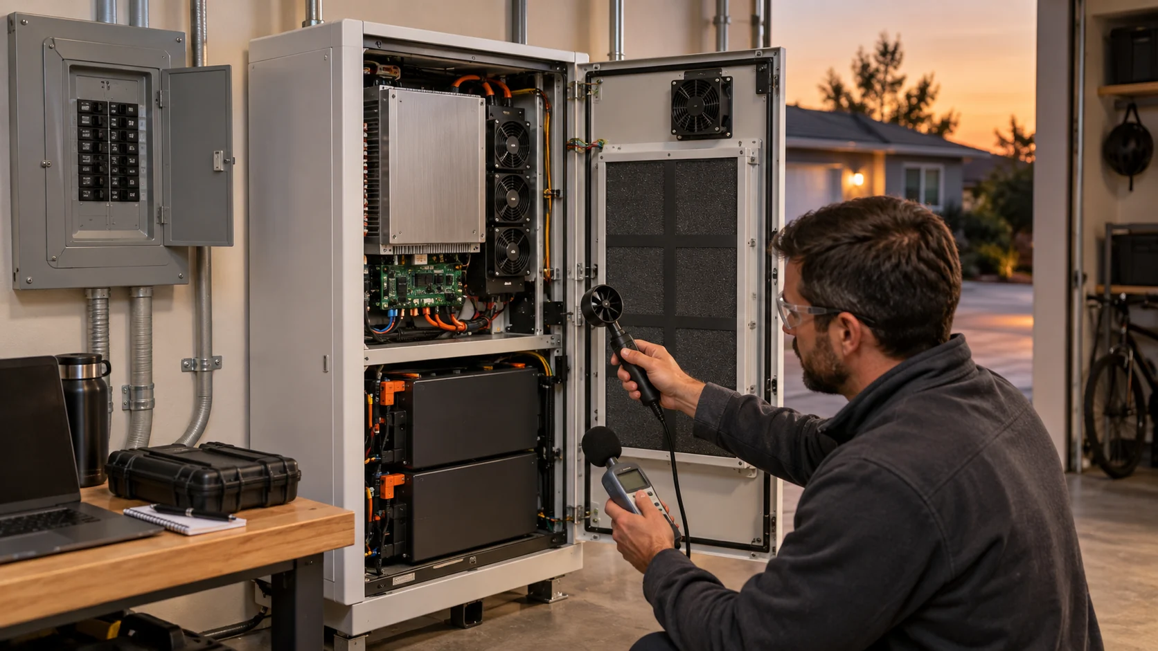
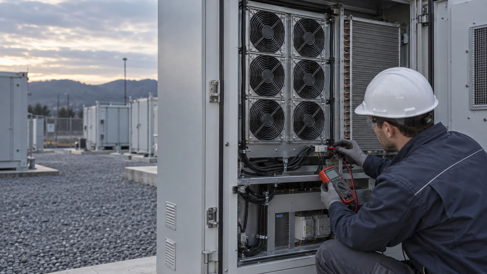
A four-wire cooling fan runs on four separate circuits: motor supply, ground return, PWM command and TACH feedback. Each circuit fails in its own way, and the failures do not announce themselves at the controller. Cable length, terminals, fuses, connector contacts and shared returns all add resistance and noise between the point where a voltage is commanded and the point where the fan actually receives it. The measurement that decides a replacement is the one taken at the fan connector, under load, with the cabinet closed and the air path installed.
The four-wire arrangement itself is standardized: the pinout of ground, supply, TACH and PWM goes back to Intel's defined fan interface, and application notes from Texas Instruments describe how the four signals behave separately. What is NOT standardized is every electrical value around them: the operating voltage window, the PWM frequency the fan accepts, the duty-to-speed map and the TACH pull-up. Those come from the exact fan and controller documents, never from an unrelated model.
This matters most in a BESS cabinet, where a fan module sits behind a filter, a coil and louvers, at the end of a harness that also carries switching loads. A technician who replaces the fan on a controller fault code alone can reinstall the fault together with the new fan.
What Each of the Four Circuits Proves
Read the four circuits as four separate tests, because each one answers a different question.
The supply circuit proves that energy reaches the fan at its connector. The ground return proves that current has a path back with low resistance; a shared return that also carries switching loads can lift the fan's ground reference and shrink the voltage the fan electronics actually see. The PWM circuit proves the command arrives with the frequency and level the fan expects. The TACH circuit proves the fan's own report reaches the controller; it says nothing about airflow through the installed filter and coil.
A reading on one circuit never substitutes for the others. A fan can spin on healthy supply and still report nothing because its TACH pull-up is missing; a controller can show a perfect PWM waveform at its own terminal while the fan connector sees two volts less than the fan window requires. The table below is the checklist to walk in order, at the fan connector, under a representative load.
| Circuit | What it proves | What it does not prove | Where it usually fails |
|---|---|---|---|
| Motor supply (V+) | Voltage at the fan connector stays inside the fan window at startup and at the representative command | That the controller bus voltage equals the fan voltage | Long cable, small cross-section, heated or corroded contacts |
| Ground return | Return path resistance stays low and the ground reference is stable | That the return is clean because the supply reading looks normal | Shared return carrying switching loads; lifted ground reference |
| PWM command | The fan receives the frequency, level and duty it is specified to accept | That one PWM arrangement suits every fan model | Frequency outside the fan range; command referenced to the wrong rail |
| TACH feedback | The fan report reaches the controller as pulses the input can read | That reported speed proves airflow through filter and coil | Missing or wrong pull-up; pulses lost to switching noise |
The Voltage Window Is Written at the Fan Connector
Every fan datasheet states an operating voltage range, and the place that range must hold is the fan connector, not the supply terminals.
The window is narrower than many field habits assume. DC fans with PWM control in the mainstream 12, 24 and 48 V classes commonly specify plus or minus ten percent: 10.8 to 13.2 V, 21.6 to 26.4 V and 43.2 to 52.8 V in current San Ace PWM lines. Below the window the motor may not start or may stall; the fan electronics do not treat a low bus as a request to run slower. And the window is not a universal constant: industrial wide-range types specify far broader ranges, for example 15 to 30 V on a 24 V rated high-vibration series, so the exact fan document decides, not the class label.
Cable resistance is what moves the connector away from the bus. A 26 AWG conductor measures about 0.134 ohm per meter. A three-meter pair, there and back, adds roughly 0.8 ohm. At a 0.8 A running current that is 0.64 V of loss; at a startup surge of 2 to 2.5 A it is 1.6 to 2.0 V. On a 24 V cabinet with a 21.6 V floor, a fan at the end of that harness starts its life 1.6 V closer to the limit than the controller display suggests. Startup is the worst case because locked-rotor current flows before the impeller turns; the standard four-wire 12 V class allows up to 1.5 A at startup against about 1 A steady.
Measure with the cabinet closed, the filter in its real state and the command at its representative level. A bus reading on an open cabinet door with the fan disconnected proves nothing about the connector under load.
Startup Current and Supply Ripple
Two supply-side behaviors that a voltmeter average will hide: the startup surge and the switching ripple riding on the bus.
Startup current runs several times the steady value for a short period on every start. The harness, the connector contacts and the branch fuse all see that surge, and a marginal contact that looks fine at 0.8 A can drop a full volt at 2.5 A while heating locally. Repeated starts in a hot cabinet age exactly that contact. This is why the connector inspection belongs to the electrical record: discoloration, spread terminals and heated housings are evidence, not cosmetics.
Ripple is the second hidden load. EC fan instructions bound the supply ripple explicitly; one 48 V EC series specifies a maximum ripple of 3.5 percent on the supply. Shared feeds that also carry switching loads, long unlaced harness runs and missing local decoupling all raise the ripple the fan electronics see, and high-frequency current steps in a long conductor turn small inductance into visible voltage spikes at the fan end. A fan that resets on PWM steps, or a TACH that glitches only when the command changes, is showing ripple behavior, not bearing behavior.
- Measure the connector during startup, not only at steady running current.
- Inspect connector contacts for heat discoloration and spread terminals before condemning the fan.
- Keep the fan feed and its return away from shared switching loads where the design allows it.
- If symptoms track PWM steps, log supply ripple at the connector, not only the average voltage.
Interactive: Estimate Voltage Loss Along the Cable
Screen the round-trip cable resistance before assuming the fan itself is degraded.
The screen is resistive only. It does not model connector contact condition, startup surge duration, ripple or the fan's own tolerance. Use it to decide whether the harness can plausibly hold the fan window; use a connector measurement under load to decide anything about a replacement.
PWM Command: Frequency Range and Speed Mapping
The PWM label covers at least two incompatible interface conventions, and the duty-to-speed map is fan-specific.
The four-wire DC fan convention keeps motor power separate from the command and defines the command near 25 kHz: the accepted range in the standard fan interface is 21 to 28 kHz. EC industrial fans commonly specify a different convention, for example 1 to 10 kHz with defined duty points such as 10 percent for minimum speed and above 95 percent for maximum speed. Feeding a 25 kHz server-fan command into an EC fan expecting a 1 to 10 kHz input, or the reverse, produces behavior that looks like a fan fault and is actually a command fault.
The duty-to-speed map is not universal either. Some fans stop at 0 percent duty; others hold a minimum speed. Some begin control only above a minimum duty with a defined low-voltage start; one EC series documents a safe start at 30 percent below nominal supply from 40 percent duty. Fan makers also state plainly that the supply itself must never be modulated with PWM; speed control belongs on the dedicated input. And when the command wire is open or disconnected, four-wire DC fans are designed to run at full speed, which turns a broken command wire into a noise complaint rather than an overheat.
So the validation record stores the command frequency, the level and reference, the duty points where the controller actually operates, and the fan document that defines all of them. The site's PWM control guide covers the control-loop side; the wiring side lives in these interface documents.
| Interface | Typical frequency range | Documented behavior to confirm |
|---|---|---|
| Four-wire DC fan, Intel convention | 21 to 28 kHz, nominal 25 kHz | Open command input runs the fan at full speed; 0 percent duty can stop the fan; level referenced to fan logic supply |
| EC industrial fan control input | 1 to 10 kHz on documented models | Minimum speed near 10 percent duty, maximum above 95 percent; some models define a low-voltage start from a minimum duty |
| Supply itself | Never modulated with PWM | Fan makers state speed control belongs on the dedicated input, not on the supply |
TACH Feedback: Two Pulses per Revolution
The TACH line reports rotation and nothing else, and only when the reading circuit lets it.
The convention is two pulses per revolution. The speed math follows directly: frequency in hertz times 30 equals speed in rpm. A 1,800 rpm fan reports 60 Hz; a 3,600 rpm fan reports 120 Hz. This gives the field a cross-check that needs only a frequency counter: compare the reported rpm against the TACH frequency at the connector. Agreement proves the fan and its report match; disagreement points at the circuit between them.
The output is an open collector with a small current rating; one 48 V EC series documents a sink capability of 10 mA. It needs a pull-up to a defined rail, and the pull-up rail, level and input threshold belong to the controller document as much as the fan document. A missing pull-up reads as zero speed on a healthy fan; a marginal one reads as intermittent dropouts that track harness vibration or PWM steps. Some EC fans replace the TACH line with a diagnostic line instead: the same 48 V family documents an output that sits low when the fan is healthy and high on fault, which is a status flag, not a speed report, and must not be counted as pulses.
One more cross-check belongs in the record: commanded speed versus reported speed at three command levels, captured in the same window as the electrical measurements. The site's TACH and RD validation guide walks that comparison in detail.
| Fan speed | TACH frequency | What disagreement suggests |
|---|---|---|
| 600 rpm | 10 Hz | Check pull-up and input threshold before trusting a low-speed report |
| 1,800 rpm | 60 Hz | A missing-pulse reading at this range usually tracks noise on the return path |
| 3,600 rpm | 120 Hz | Above this range, confirm the controller input counts two-pulse signals correctly |
One Command, Two Wiring Outcomes
The same controller, the same fan model and the same command can produce two different records, and the harness decides which one.
On the left, a short dedicated harness: connector voltage stays a half volt under the bus, TACH pulses arrive two per revolution, and the tach-to-speed math agrees with the command. On the right, a long harness shared with switching loads: startup and load current pull the connector below the window, and the TACH line drops pulses exactly when the command steps. Both fans spin. Only one record identifies its cause.
The failure pattern to remember from the right panel is the replacement trap: the controller sees a TACH anomaly, the fan is swapped, the fault clears for a week and returns. The fan was never the component that failed. The two minutes spent at the connector with a meter and a frequency counter are what separate these outcomes.

Failure Patterns That Lead to Wrong Replacement
Four recurring field patterns, and the two-minute check that resolves each one.
Each pattern below ends the same way when it is misread: a healthy fan comes out and the fault returns. The confirm step is deliberately cheap, because the point of the table is to spend minutes, not hours, before touching the hardware.
| Field symptom | Likely cause | Confirm by |
|---|---|---|
| Fan twitches at intervals but does not spin | Impeller blocked or bearing seized; protection restarts the motor | Power off, rotate by hand; check for cable or debris contact |
| Fan runs, controller reports zero speed | TACH circuit: missing pull-up, broken wire or wrong input type | Count TACH pulses at the connector and compare against speed times 30 |
| Fan runs at full speed constantly | Open PWM command circuit; the convention drives full speed on an open input | Scope the command at the fan connector, not at the controller terminal |
| Fault clears after fan replacement, then returns | Harness voltage loss or connector contact aging | Log connector voltage through startup and a full command cycle |
| Speed reading glitches only when the command steps | Supply ripple or shared-return noise reaching the fan electronics | Log ripple at the connector during command steps |
MEGA Tech: Selection by Interface and Operating Point
A replacement fan is an electrical assembly with an air-path result, and we select and validate it as both.
What we do: MEGA Tech manufactures custom DC and EC cooling fans, axial and backward-curved centrifugal, and develops cost-competitive replacements for Sanyo Denki SAN ACE, SUNON, Delta, NMB and ebm-papst reference parts. Selection is by operating point and interface, not by part number: we review the installed pressure and airflow duty, the voltage window measured at the fan, startup and running current, the PWM frequency and duty map the controller actually sends, and the TACH or diagnostic behavior the controller expects. Samples are validated on the customer's own unit, with the filter, coil, louver and harness in place.
What we need from you: the current fan label or drawing, the airflow and static pressure at the installed operating point with the temperature and altitude basis, the supply voltage range at the fan connector, the control interface document or the measured command behavior, connector and lead requirements, space, noise and life targets. With those inputs we can propose a candidate and stand behind its interface, not just its curve.
Where the boundary sits: we do not supply coils, liquid cooling loops, cabinet controllers or cabinet safety design, and we do not own emergency ventilation. Normal cooling diagnostics stay separate from battery-safety functions. A fan that matches the interface and passes the operating point still earns its place through the sample validation record.
Recommended Fan Starting Points
These catalogue series may be suitable starting points for this application. Final selection depends on the installed airflow, static pressure, voltage, noise target and operating environment.
Request a sample for validation on your equipment.
Engineer FAQ: Fan Connector Voltage, PWM and TACH
Short answers to the questions this diagnostic raises most often.
Q: Does 24 V at the controller prove 24 V at the fan? A: No. The window is specified at the fan connector, and cable resistance plus startup current decide what arrives there. Measure under load with the cabinet closed.
Q: Is every PWM fan input the same? A: No. Four-wire DC fans conventionally accept 21 to 28 kHz near 25 kHz; many EC industrial fans specify 1 to 10 kHz with different duty points. The exact fan document decides.
Q: Does normal TACH feedback prove the fan delivers airflow? A: No. Two pulses per revolution report rotation. Pair the report with installed pressure and temperature evidence before calling the cooling healthy.
Q: Why did the fault return after the fan was replaced? A: The most common pattern is harness voltage loss or connector contact aging. Log connector voltage through startup and a command cycle before ordering another fan.
Q: Can the fan supply be modulated with PWM for speed control? A: No. Fan makers state that speed control belongs on the dedicated input; modulating the supply is outside the interface and can damage EC electronics.
Q: What pulls the TACH line up, and does it matter? A: The controller side does, to a defined rail, and it matters: a missing pull-up reads zero speed on a healthy fan, and a marginal one reads dropouts.
Questions for a Design Review
Seven questions that keep the fan interface honest before a BESS design is released.
These questions assume the four-circuit record above exists. If it does not, collecting it is the first action item, because every question below reads from it.
- Has the voltage window been measured at the fan connector during startup, not only at steady current?
- Is the PWM frequency, level and duty map the controller sends written against the exact fan document?
- Has the TACH reading circuit, its pull-up rail and its pulse count been confirmed against the actual fan?
- Do diagnostic-line fans and TACH-line fans use matching controller inputs in this design?
- What connector contact rating and cable cross-section does the startup surge justify, and is that documented?
- Does the acceptance record time-align electrical readings with filter state, pressure and named temperatures?
- If a fan is replaced in service, what evidence distinguishes a fan fault from a harness fault in the record?