Custom Cooling Fans for Data Center Fan Walls
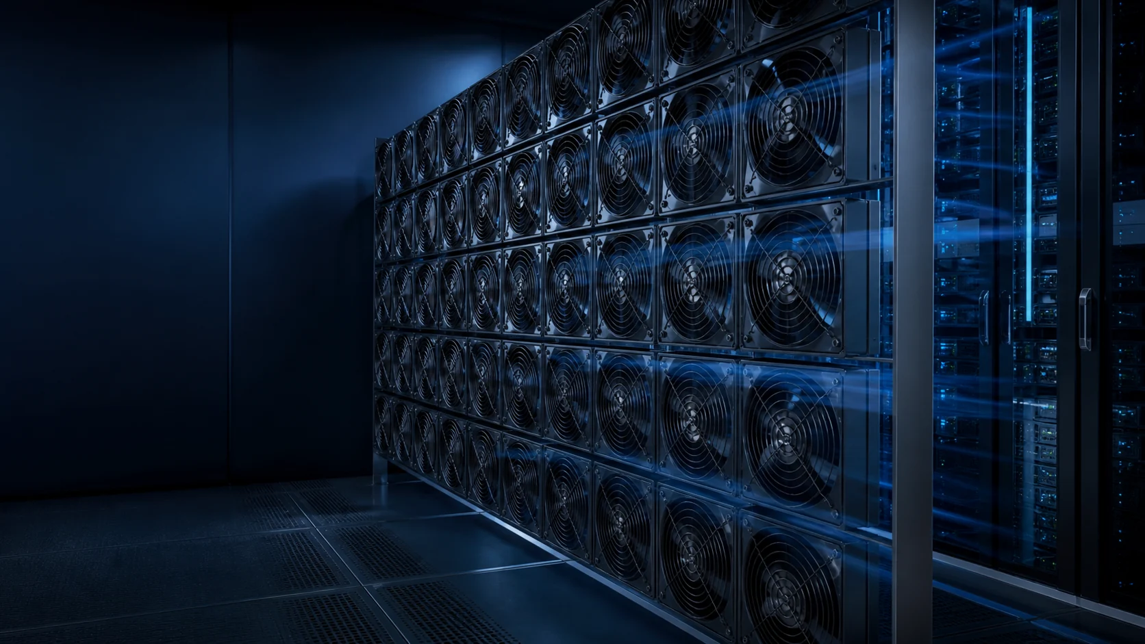
A data center fan wall is a coordinated air-moving system. The fan module, plenum, dampers, filters, coil and controls must be reviewed as one air path.
MEGA Tech supplies custom cooling fans and air-path engineering support for data center and AI data center fan-wall projects. We help teams define the operating point, compare fan options, prepare samples and validate the installed airflow path before a fan configuration is released.
This page is about the fan and its interface with the system. MEGA Tech does not supply the complete fan-wall cabinet, air-handler, coil, facility controls or site safety design. Those responsibilities remain with the system integrator. For broader system context, read our data center fan-wall article and AI data-center cooling application page.
The practical starting point is not a headline CFM value. It is the airflow required at the pressure drop of the installed fan wall, under normal, loaded-filter and one-module-out conditions.
What a Fan Wall Must Control
Fan wall cooling fan selection starts with the air path and duty point, then works backward to the fan module.
A fan wall normally moves air through a shared plenum and downstream resistance. Depending on the installation, that resistance can include filters, coils, dampers, acoustic treatment, transitions, grilles and the connected room or rack path.
Record the required total airflow, the pressure at that airflow, the number of operating modules, the available envelope and the control method. Free-air airflow and maximum static pressure are endpoint values; neither one alone describes the installed duty point.
For an AI data center fan wall, also define the inlet-temperature basis, expected heat-load range, sensor locations, service state and the airflow distribution requirement across the downstream face.

- Total airflow and static pressure at that airflow
- Fan-module count and available installation envelope
- Filter, coil, damper and plenum pressure losses
- Temperature, acoustics, vibration and service constraints
- Control interface, alarm behavior and airflow distribution target
Airflow, Pressure Drop and the Fan-Wall Operating Point
The useful question is how much airflow the fan wall maintains at the resistance of the installed system.
Build a resistance budget before selecting a fan. Include the clean and loaded filter states, coil or heat-exchanger resistance, damper position, plenum geometry, transition losses and any connected equipment. If the supplier provides a pressure-drop curve, use it at the intended airflow range.
Parallel fan modules share the total airflow, but they do not remove system resistance. The combined fan curve and the system resistance curve still determine the operating point. Module spacing, inlet clearance and uneven plenum pressure can make the measured distribution differ from a simple arithmetic split.
Do not publish a product performance value from an illustrative curve. Candidate values should come from the relevant MEGA Tech laboratory record and then be checked in the representative air path.
N+1 Airflow and Fan-Wall Redundancy
N+1 airflow is an acceptance condition, not a label that can be inferred from the number of installed fans.
Define what one-module-out means for the project: a stopped motor, an electrically isolated module, a closed damper, a removed module or another service state. Each state can produce a different pressure and reverse-flow condition.
The review should record normal airflow, one-module-out airflow, downstream temperature change, pressure distribution, alarm response and whether the failed position allows reverse flow. It should also record whether the remaining modules stay within their intended voltage, speed and noise limits.
An individual fan datasheet cannot confirm fan wall redundancy. N+1 evidence requires a physical or representative system test with the relevant module stopped or isolated. Until that record exists, describe the result as an engineering target or validation plan.

Backdraft Dampers, Reverse Flow and Isolation
A stopped module can become an unintended bypass path unless isolation and reverse-flow behavior are reviewed.
Backdraft dampers or other isolation features may be used to limit reverse flow through a stopped fan. Their cracking behavior, leakage, pressure loss, orientation and maintenance condition become part of the system resistance budget.
Check the transition between normal operation, commanded stop, power loss and service removal. A damper that protects redundancy may add pressure drop when open; a low-resistance path may allow reverse flow when a module is stopped. The correct trade-off depends on the system integrator's design and test criteria.
The fan selection review should therefore include the damper state and the module's electrical fault behavior, rather than treating the damper as an independent accessory.

Filters, Coils and Degraded-State Airflow
A fan wall that passes a clean-filter test may not meet the same airflow target after resistance increases.
Define at least the clean and loaded filter conditions used for selection. If a coil or heat exchanger is in the path, request its pressure-drop information over the intended airflow range. If the data is unavailable, treat the estimate as provisional and plan a representative validation.
Control logic should not hide a degraded air path. Monitor the variables that matter to the system, such as differential pressure, fan speed, airflow indication, temperature and alarm state, using the integrator's control architecture.
A sample evaluation should include the highest credible resistance state that the project will accept, with the test condition written down. This makes a later maintenance or filter change less likely to create an unrecognized thermal margin problem.
- Clean and loaded filter resistance
- Coil or heat-exchanger pressure drop
- Fan speed and control margin
- Airflow indication and alarm threshold
- Maintenance state used for acceptance
Controls, Sensors and Serviceability
Fan wall controls must coordinate speed, feedback, alarms and maintenance states across multiple modules.
Confirm supply voltage and tolerance, PWM or analog command, startup behavior, minimum speed, FG or tachometer feedback, RD or alarm output, connector pinout and cable access for the selected fan. These details must be checked against the customer's controller; they should not be assumed from another model.
Sensor placement affects the control result. Review where differential pressure, temperature and airflow sensors see the system, and check for hunting caused by delay, uneven plenum pressure or a fan module responding differently from its neighbors.
Serviceability belongs in the same review: identify the failed module, isolate it safely, access the connector, remove the module and restore the intended airflow path without introducing an untested configuration.

Airflow Distribution, Noise and Vibration
Total airflow can look acceptable while an uneven plenum or acoustic problem still affects the equipment downstream.
Measure or estimate distribution across the downstream face, not only the total flow. Check for short circuits, blocked regions, inlet recirculation, fan-to-fan interaction and plenum dead zones. The acceptable distribution criterion belongs to the system design and should be agreed before testing.
Noise and vibration can change after installation because of blade-passing tones, structural resonance, turbulence at grilles or dampers and mounting stiffness. Record the measurement location, operating state and background condition when comparing samples.
MEGA Tech can support fan-level and air-path review, but the complete room, cabinet and facility acoustic design remains with the system integrator.

Fan-Wall Airflow Validation and Commissioning
Commissioning turns a fan selection into evidence that the installed fan wall behaves as intended.
Start with a documented test matrix: normal operation, commanded speed changes, minimum accepted speed, clean and loaded resistance states, one-module-out operation and relevant alarm or service states. Record the fan configuration, controller settings, sensor locations and environmental basis.
Measure the variables needed to make a release decision: total and distributed airflow, pressure, fan speed, voltage, current, temperatures, control response, alarm behavior, noise and vibration. The exact pass/fail limits must come from the system requirement or customer acceptance plan.
Close the review with a configuration record. Keep the tested fan revision, connector, controller setting, damper state and installation arrangement tied to the result so a later substitution does not silently change the evidence.
What MEGA Tech Provides for Fan-Wall Projects
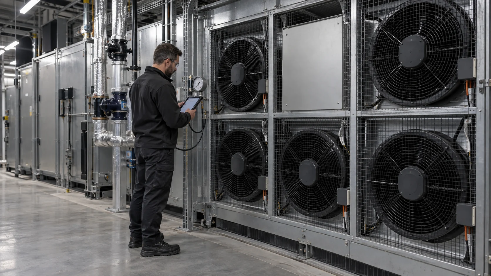
MEGA Tech helps equipment teams move from a fan-wall requirement to a custom fan configuration that can be checked in the customer's application.
Our support may include reviewing airflow and static pressure, comparing custom DC fan options by operating condition, checking voltage and control interfaces, preparing sample configurations, reviewing replacement candidates and supporting installed-air-path validation.
Selection is based on the operating condition, not only on a frame size or original part number. Fans with the same external size can differ in airflow, pressure capability, speed control, acoustic behavior, electrical interface and failure response.
MEGA Tech does not supply the complete Fan Wall, air-handler cabinet, plenum, coils, liquid loops, facility controllers or site safety system. Those remain with the system integrator.
Engineer FAQ
Use these questions to define the next measurement or sample-validation step.
Q: Does MEGA Tech supply a complete fan wall? A: No. MEGA Tech supplies custom cooling fans and air-path engineering support; the complete fan-wall assembly and facility system remain with the system integrator.
Q: How should I select a fan-wall cooling fan? A: Provide airflow and static pressure at that airflow, the module arrangement, resistance chain, voltage, control interface, temperature, noise target and service requirements.
Q: Can a fan-wall system claim N+1 redundancy from the fan count? A: No. N+1 airflow and fan wall redundancy require a defined one-module-out test with measured airflow, pressure, temperature and alarm response.
Q: Do I need filter and coil pressure-drop data? A: It is strongly preferred. Without it, the operating point is provisional and should be confirmed with representative samples and installed testing.
Q: Can you support PWM, FG and RD interfaces? A: These interfaces must be confirmed for the selected fan and checked against the customer's controller and wiring.
Q: What should I send for a first review? A: Send fan size and mounting, voltage, airflow, static pressure or resistance data, quantity, controls, noise target, environment and any N+1 requirement.