The Question Is Not Which Layout Is Stronger
Two fans can be arranged to add pressure or to add flow. Neither arrangement guarantees the result your enclosure needs.
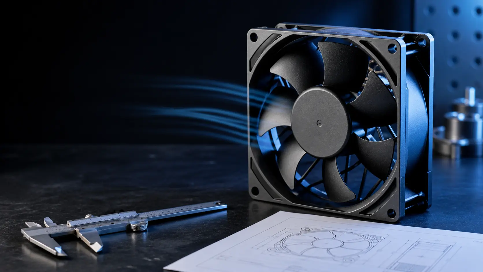
Engineering teams often reach for a second fan after a prototype misses temperature. The obvious question is whether to place it behind the first fan or beside it. The more useful question comes first: what pressure and airflow must the completed enclosure deliver at its actual resistance? The answer sits at the intersection of the combined fan curve and the system curve, not in a multiplication of catalogue CFM.
AMCA's Fans and Systems guidance describes the ideal distinction clearly: identical fans in series combine pressure capability at a given airflow, while identical fans in parallel combine airflow capability at a given pressure. The same guidance also warns that restricted or non-straight inlet flow, increased downstream resistance and interaction between stages make installed performance lower than the theoretical sum.
That matters in compact electronics. A dense heatsink, filter or narrow duct can make pressure the limiting resource. A large, open cabinet may instead need more volume at modest pressure. Start with the path, then use the arrangement that moves the required operating point in the useful direction.
What Series and Parallel Change on a Fan Curve
Series shifts the pressure envelope. Parallel shifts the flow envelope. The system curve decides how much of either shift becomes useful cooling.
With two matched fans in series, the same mass airflow passes through both stages. In an idealised first-pass model, the pressure contributions add at a given flow. This is why a staged arrangement can be useful when a restrictive filter, fin stack or narrow channel has moved the required operating point toward the high-pressure end of the candidate fan curve.
With two matched fans in parallel, each fan supplies part of the total flow at a common pressure. In an idealised first-pass model, the individual flow rates add at a given pressure. That can suit a broad plenum, a fan wall, or a large enclosure where the required flow is high and the resistance is comparatively low.
Neither statement means an installed system gets exactly two times the pressure or two times the flow. The combined curve has to be overlaid with the changed system curve. Shared grilles, filter area, backdraft devices, leakage and the new airflow velocity can all change the resistance at the same time.
| Arrangement | Ideal combined-curve tendency | Useful when | Key validation risk |
|---|---|---|---|
| Series, front to back | More pressure at a given flow | Restrictive path, dense fins, filter or compact duct | Stage-to-stage inlet distortion, noise, stall or unstable operation |
| Parallel, side by side | More flow at a given pressure | Wide plenum or high flow requirement with lower resistance | Uneven sharing, recirculation, backflow through a stopped fan |
| One larger fan | One measured curve and fewer interfaces | Space permits and redundancy is not required | Frame, mounting or service constraints |
Interactive Model: Move the Working Point
Select an arrangement and change the relative system resistance. The graph is deliberately normalised so it teaches the physics without pretending to be a product datasheet.
The simplified curves below represent two matched fans at the same speed. They show why a low-resistance system tends to benefit more from parallel flow capacity, while a high-resistance system can benefit more from additional series pressure. They do not include blade interaction, motor heat, inlet swirl, leakage or a real fan's stall shape.
Use it to frame a design review, then replace the model with the selected fan's measured P-Q data and a measured or correlated system curve. The final release decision belongs to the representative enclosure, including grille, filter, heat sink, cabling and expected service condition.
Why the Theoretical Gain Often Disappears
Adding a fan changes the air path. If the restriction stays or the inlet gets worse, the second fan may add less useful cooling than expected.
In a series pair, the outlet of the first stage becomes the inlet of the second. Swirl, uneven velocity and insufficient transition space can make the second stage operate in a distorted flow field. AMCA identifies adverse inlet and outlet conditions as system effect, which can reduce performance, raise noise and add vibration. The practical response is not to apply a universal spacing number, but to test the proposed geometry with the selected fans.
In a parallel pair, a shared restriction can become the bottleneck. Two fans feeding the same undersized grille, filter or exhaust slot increase velocity through that restriction, so the system pressure drop rises. A stopped fan can also become a leakage or reverse-flow path unless the design includes suitable isolation, a damper strategy or a validated failure mode.
Mismatch adds a separate problem. Different fan models, control commands, wear states or supply conditions can shift one fan toward an unstable region while the other carries more flow. Use matched fans where possible, log each fan's speed and electrical state, and validate normal as well as one-fan-down operation.
- Check whether a shared grille, filter or outlet is now the dominant pressure loss.
- Keep both fans matched in model, voltage, control state and rotation direction unless a validated design says otherwise.
- Treat a stopped parallel fan as a potential reverse-flow path, not an inactive blank wall.
- Record pressure, flow, current, RPM, temperature and noise together during the array test.
Worked Screening Example: A Filtered Electronics Enclosure
Use the example as a calculation workflow, not as a universal fan recommendation.
Assume a prototype requires 60 units of relative airflow at its allowed temperature rise. A first candidate, evaluated against the clean enclosure curve, reaches the target only narrowly. When the filter's measured service-state pressure drop is added, the system curve steepens and the predicted operating point falls below the target. The question is then whether the remaining layout needs more pressure capability, lower resistance or both.
If the dominant loss is the filter and fin path, a series option may move the combined curve upward enough to recover the point, provided the staged inlet condition is validated. If the dominant requirement is simply more flow through a wide, low-resistance plenum, parallel fans may be more effective. If the grille is undersized, neither arrangement is the first correction: opening the restriction can improve cooling at the same speed and with less acoustic penalty.
The acceptance result should state the exact configuration: fan model, voltage, speed command, filter condition, cover and grille, pressure measurement planes, ambient condition, delivered flow or differential pressure, hotspot temperature, input power and sound result. That turns a promising simulation into a repeatable production requirement.
Validation Plan Before You Release the BOM
A dual-fan arrangement is a new cooling system. Validate it as an assembly, not as two separate datasheets.
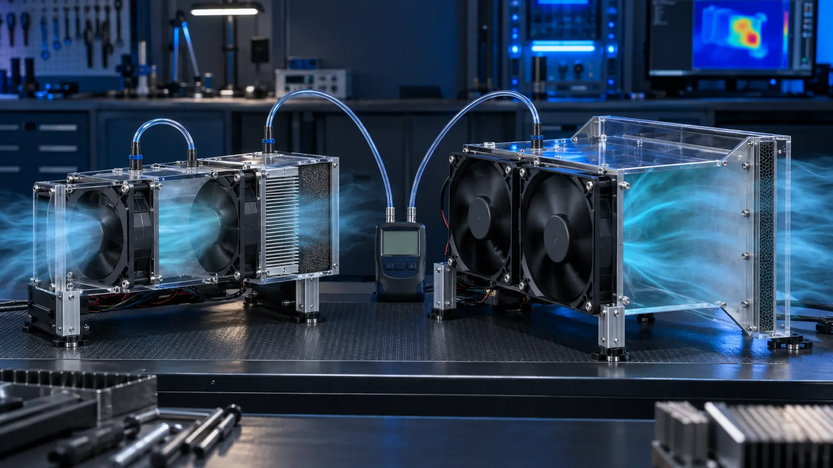
Start with the actual mechanical stack: intended fan guards, gaskets, shroud or duct, heat sink, filter, cabling and covers installed. Establish a clean-condition baseline at the agreed ambient, supply voltage and control command. Measure enough evidence to connect electrical input to the delivered thermal result.
Repeat at the realistic degradation state. For a filtered product, this means the agreed service-state filter pressure drop or representative loaded condition. For a redundant parallel arrangement, repeat with one fan stopped or electrically isolated and document any backflow, remaining thermal margin and alarm response. For series stages, inspect noise, vibration and stability through the expected speed range.
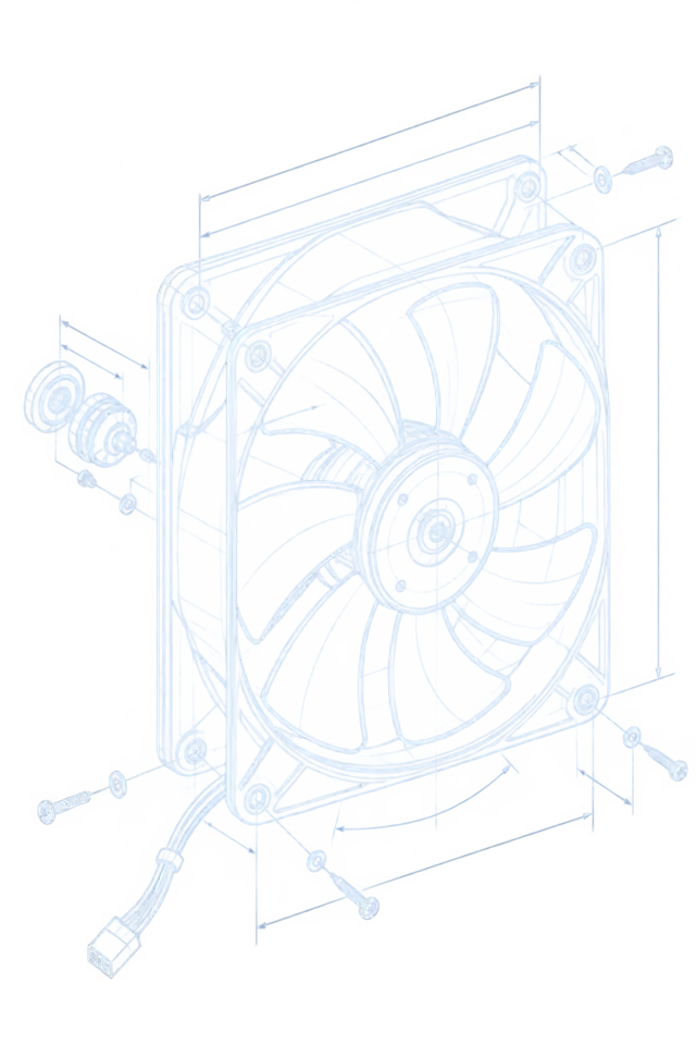
MEGA Tech can use this evidence to define a customised sample around the required frame, pressure duty, speed, PWM, FG or RD signal, connector, wiring, bearing and mounting. The goal is not to promise a theoretical multiplier. It is to approve a practical cooling assembly that stays inside the agreed limits.
- Measured P-Q information at the selected voltage and command condition.
- Pressure or airflow measurement at defined planes in the assembled enclosure.
- Hotspot and inlet temperature at normal and degraded restriction conditions.
- Per-fan RPM, voltage, current and fault-signal record where applicable.
- Noise, vibration and one-fan-down behaviour for array or redundancy designs.
- A production release record that preserves the approved air-path geometry.
Engineer FAQ: Series and Parallel Cooling Fans
The useful answer always returns to the measured fan curve, system curve and installed geometry.
Q: Will two fans in series double static pressure? A: The ideal combined fan curve adds the stages' pressure capability at a given airflow. The installed result can be lower because the second fan sees the first stage's outlet flow, and the system curve, leakage and system effect still determine the operating point.
Q: Will two parallel fans double delivered airflow? A: Only the ideal combined curve approximately doubles flow capability at a common pressure. Shared restrictions often raise system resistance as total flow rises, so the installed gain can be much smaller. Measure the complete array in the actual path.
Q: Can I put different fans in series or parallel? A: It is possible only with a deliberate curve and control analysis. Different models, speeds or supplies can share flow unevenly or create unstable operation. For a first design, matched fans and measured combined performance are the safer basis.
Q: Is a bigger single fan better than two smaller fans? A: Sometimes. A single fan reduces interfaces and interaction, but packaging, redundancy, serviceability, pressure duty and control requirements may favour an array. Compare measured operating point, power, noise and failure behaviour rather than frame count alone.
Q: What information should I send for a custom dual-fan sample? A: Send the heat load, required airflow or pressure, enclosure drawing, restriction chain, available space, voltage, control and feedback requirements, noise limit, duty cycle, environment and sample quantity. Include clean and worst-case filter or path conditions where relevant.