The Fan Wall Had Spare Fans — But the Failure Test Still Failed
An anonymized European data-center cooling integrator had a modular fan-wall unit for a high-density AI hall. The drawing showed N+1 fans, yet the first fault test produced less useful airflow than expected.
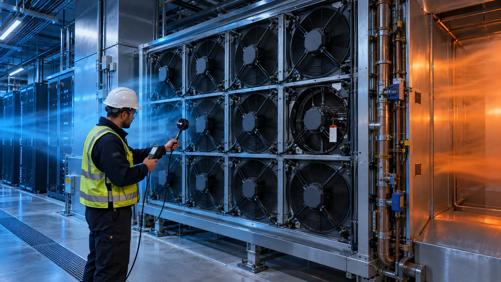
The healthy fans accelerated after one module was switched off, but the failed opening became a low-resistance bypass path. Part of the pressure generated by the running fans moved backward through the idle fan position instead of crossing the coil and reaching the supply plenum. The fan wall still looked redundant on paper; the assembled air path was not yet proven redundant.
MEGA Tech reviewed the fan module envelope, coil resistance, plenum geometry, control logic, fan feedback and maintenance access. The goal was to develop a controlled sample and test method that answered a practical question: after the defined fan failure, does the unit still deliver the required airflow and pressure at the actual system resistance?
The integrator identity, facility load and acceptance limits remain confidential. This case explains the engineering workflow and uses clearly labelled estimates rather than presenting invented customer results as measured data.
Why “N+1 Fans” Is Not the Same as N+1 Cooling
Redundancy exists only when the cooling system remains inside its thermal and airflow limits after the defined failure.
ASHRAE material on data-center redundancy warns that N+1 can describe component redundancy without proving a complete concurrently maintainable system. For fan walls, the same caution applies at a smaller scale: one additional fan does not automatically prove that the surviving fans can overcome the system resistance, distribute air evenly or avoid reverse flow through the failed position.
A fan wall is a parallel system. When one fan stops, the available fan curve changes, the pressure distribution changes and the remaining fans may move to a different operating point. If the stopped fan is not isolated, the opening can become a recirculation path. The result depends on pressure difference, fan internal resistance, backdraft control, blanking geometry and the surrounding plenum.
The first design-review question is therefore not “How many fans are installed?” It is “What does the assembled wall deliver at the specified system pressure in normal and fault states?” The answer must come from a fan-array curve or a test that represents the actual coil, filters, dampers and supply path.
The Problem in Operation: Healthy Fans Were Feeding the Dead Position
The integrator's first test revealed a pressure short circuit rather than a simple one-fan airflow loss.
With all modules operating, the fan wall met the preliminary supply target. When one module was disabled, the remaining fans increased speed under the existing control command. The outlet measurement did not fall by the expected single-fan percentage because some air circulated across the failed position and returned through the plenum. A total-flow reading without local pressure measurements hid the distribution problem.
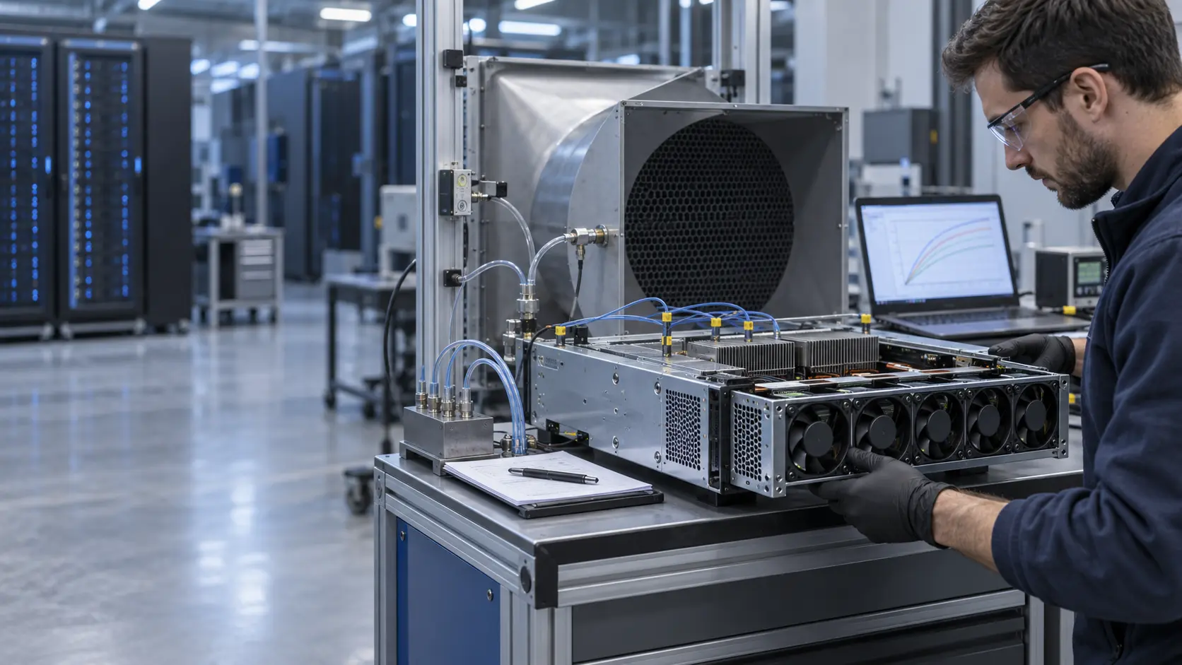
The review added pressure taps upstream and downstream of the coil, a traverse across the supply face, fan RPM or FG feedback and a temperature map downstream of the cooling coil. The team also recorded the failed module's inlet-to-outlet pressure difference and checked whether the impeller coasted or rotated backward. These measurements separated three causes: reduced fan capacity, reverse bypass and uneven plenum distribution.
A second issue was control headroom. If the normal operating state already used every fan near maximum command, the controller had no safe reserve after a failure. A stable N+1 design needs both enough fan capacity and a defined control response.
Interactive: Watch the Array Rebalance After One Fan Stops
The animated schematic shows why a failed module can steal capacity from healthy fans when the opening is not controlled.
The figure is qualitative, not CFD or a measured fan curve. In the normal state, the parallel fans share the plenum resistance. In the uncontrolled fault state, the pressure field can drive air through the stopped module. In the controlled state, the failed position is isolated or otherwise managed, and the remaining fans are commanded against the new array curve.
The test sequence used normal operation, one-fan stop, automatic fault response, stabilized N+1 operation and recovery after replacement. Each state recorded total airflow, local velocity, pressure across the coil, supply temperature, fan current, RPM or FG, acoustic behavior and alarm timing. The fault response was not accepted just because the remaining fans reached a higher RPM.

Sample 01: Build the Fan Array Around the Real Coil and Plenum
A fan module should be selected at the operating point created by the assembled wall, not from free-air airflow added together across the catalogue.
The customer supplied the coil pressure-drop curve, design airflow, supply pressure target, fan cut-out, module spacing, voltage, control interface, acoustic limit and maintenance clearances. MEGA Tech compared compact high-static-pressure EC fan directions and reviewed how the fan frame, guard and sealing would behave in the plenum.
A planning estimate illustrates why the system curve matters. If a cooling module needs 40,000 m3/h at an assumed 500 Pa total external resistance, a ten-fan array would need an average of 4,000 m3/h per running fan at that pressure before redundancy. With one fan unavailable, nine fans would need about 4,444 m3/h each to maintain the same total flow. These are arithmetic planning values only; the real array curve, coil resistance and leakage must determine the final fan count.
The mechanical review included fan extraction, connector access, service doors, blanking or backflow-control options, vibration isolation and whether a failed module could be replaced without removing chilled-water piping. A redundant fan that cannot be serviced while the unit remains safe is not a complete reliability solution.
Sample 02: Validate Normal, Fault and Restricted-Bypass Curves
The sample test compared the operating point in the states that operators actually care about.
The normal curve was measured with all fans active. The N+1 curve was measured with one fan disabled and the remaining fans following the proposed control logic. A third restricted-bypass state was used to evaluate the effect of isolating the failed opening. This did not assume that a blanking device or backdraft damper was automatically correct; it measured the pressure, airflow and acoustic tradeoff.
The controls team then tuned a fault response using fan feedback and differential pressure. The response included fault detection, a controlled ramp of the surviving fans and an alarm if the supply airflow or pressure remained below the defined limit. The minimum command was checked because an array can become unstable or noisy when fans operate too close to their low-speed region.
The buyer's acceptance sheet should state the airflow, pressure, supply-temperature limit, maximum fan command, acoustic condition, fault-detection time and recovery behavior for each state. “N+1 available” is not a sufficient acceptance criterion by itself.
Sample 03: Check Acoustics, Vibration and Part-Load Efficiency
Fan walls are often chosen for modularity and efficiency, but poor array matching can create tonal noise, uneven velocity and wasted fan power.
The acoustic test separated broadband airflow noise from tonal blade-pass components and structure-borne vibration. The fault state was included because the remaining fans may accelerate, changing both sound level and frequency content. The team measured near the unit and at the occupied space rather than relying on a single component value.
Part-load control was also reviewed. ASHRAE publications describe redundancy strategies that balance reliability and energy use; a fan wall should not run every module at high speed when the cooling load is low. At the same time, excessive fan shutdown can worsen distribution or leave too little headroom for a fault. The practical control curve must be tested against the coil and plenum.
The final sample therefore included normal duty, low-load duty, high-load duty, one-fan fault, sensor fault and restart behavior. The goal was a repeatable commissioning package, not a claim that every fan wall should use the same speed schedule.
Validation Result: Redundancy Became a Measured Operating Envelope
The completed sample gave the integrator three documented states: normal airflow, controlled N+1 airflow and a defined alarm or derating response when the available margin was exhausted.
The transferable result was the test method. The fan array was judged at the real external pressure, with the coil, plenum, sealing and supply path installed. The fault state was recorded as its own operating point, and the team could see whether capacity was lost through the failed fan, through pressure redistribution or through a control limitation.
No universal airflow or capacity number is claimed because fan-wall performance depends on coil design, system resistance, containment and the selected fan. The correct release package should contain the individual fan P-Q curve, array operating points, fault-state curve, electrical input, feedback behavior, acoustic test method, mounting drawing and maintenance instructions.
For procurement, this also creates a fair comparison. A replacement fan is not equivalent because the frame fits; it must produce the required pressure and airflow in the wall, use the required control interface and preserve the defined fault response.
How MEGA Tech Supports Fan-Wall and AI Data-Center Fan Customization
MEGA Tech works from the installed operating point and the customer's fan-wall envelope, then develops samples that can be tested in the assembled unit.
We can review compact EC axial and centrifugal directions, voltage and PWM requirements, FG/RD feedback, connector and mounting details, bearing and life targets, acoustic limits, contamination exposure and small first-build quantities. For a replacement, we compare the original fan's operating envelope rather than promising a drop-in result from dimensions alone.
Please provide the design airflow at pressure, coil and filter resistance, number of running and redundant fans, fan cut-out, control range, supply voltage, feedback or alarm requirements, ambient conditions, noise target and service constraints. If the data is incomplete, an installed photograph, current fan part number and a few pressure measurements can still start the review.
Our scope is fan and air-path engineering, sample tuning and comparative validation. The data-center integrator remains responsible for the coil, controls, containment, facility safety, chilled-water system and final commissioning limits.
Engineer Questions About This Fan-Wall Case
Use these questions before accepting a fan wall as N+1 redundant.
Q: Does one spare fan automatically make a fan wall N+1? A: No. The surviving array must meet the defined airflow, pressure, thermal and acoustic limits after the fault, and the failed opening must not create unacceptable reverse flow.
Q: Should a failed fan always be blanked? A: Not automatically. Isolation can reduce bypass, but it also adds pressure drop and may affect service or acoustics. Test the assembled design.
Q: What measurements prove the fault state? A: Measure total airflow, local velocity distribution, coil pressure drop, supply pressure, temperatures, fan command, RPM or FG, current, noise and alarm timing.
Q: Can healthy fans simply increase PWM? A: Only if the remaining fans have operating-point and electrical headroom. A PWM increase without a system-curve check can move the array into an unstable, noisy or inefficient condition.
Q: What should I send for a custom specification? A: Send the system airflow and pressure target, coil/filter curve, fan quantity, size, voltage, PWM/FG/RD interface, sound limit, environment, service constraints and required fault state.
Need a Fan-Wall P-Q Curve or Custom Specification?
Send the design airflow, external static pressure, fan size, voltage, quantity, control interface, noise limit and the defined failure state. MEGA Tech will review the installed operating point before recommending a sample.
Start with the product information page, or contact an engineer directly. Include the current fan model, P-Q curve, coil or filter pressure drop and any installation photos available. This lets us separate a fan-capacity issue from a plenum, bypass, control or maintenance issue before the production BOM is locked.