The Array Passed Normal Operation but Failed the One-Fan Test
An anonymised AI infrastructure integrator needed to validate a fan array for a dense server rack and a BESS cabinet after discovering that one stopped fan changed the airflow of the remaining modules.
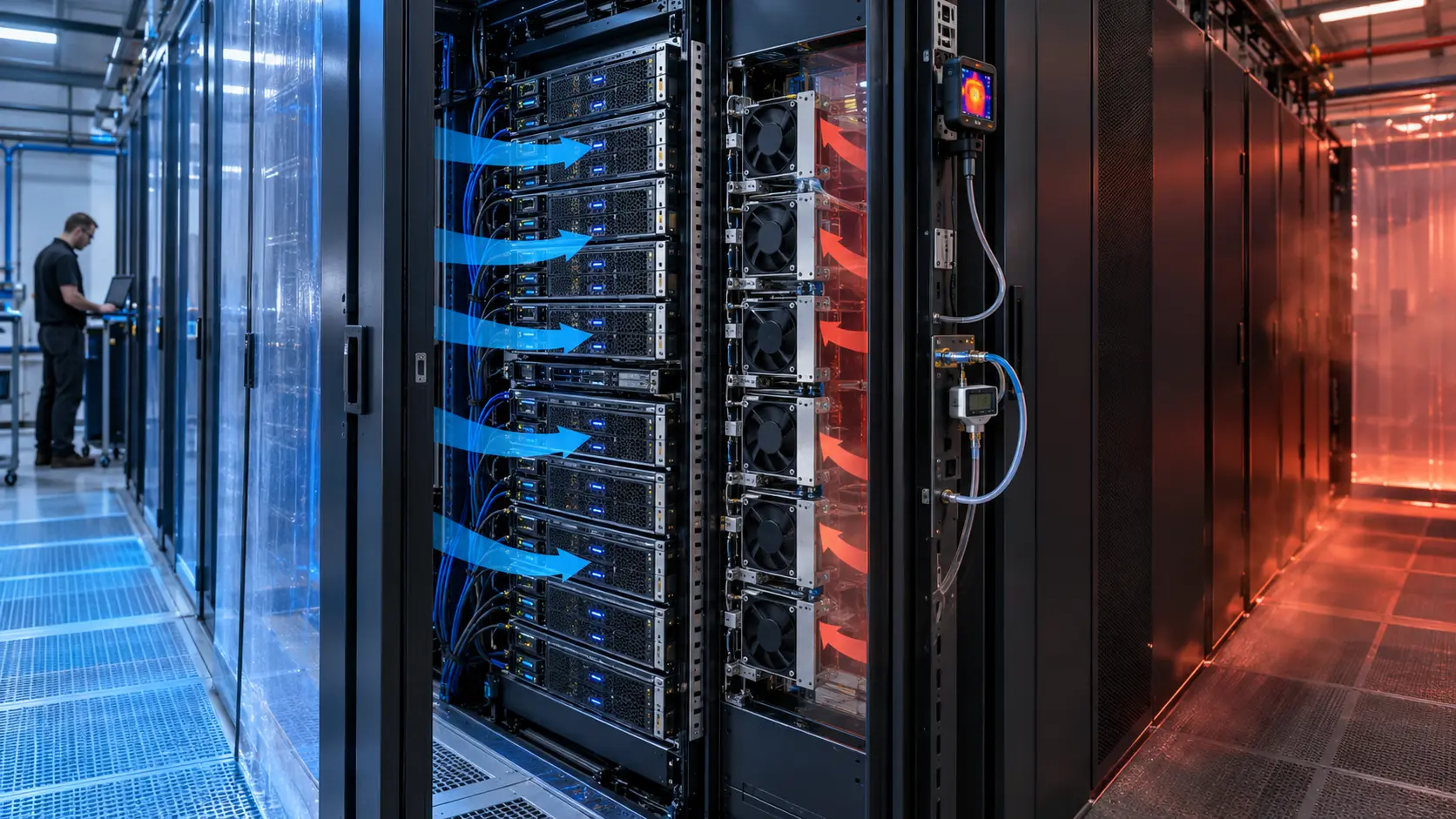
During normal operation, the array reached the expected command and the rack or cabinet temperature remained within the project's working range. The first fault test disabled one fan and checked the alarm output. The alarm appeared, but the remaining fans did not simply provide the expected fraction of total airflow. A stopped module became an open path, and part of the pressure created by the operating fans moved backward through it rather than through the heat-producing equipment.
The result was a misleading pass if the review looked only at rotation feedback. The healthy fans were spinning, the controller had increased their command and the fault signal was visible, yet local server or battery temperatures rose faster than the simple fan-count estimate predicted. The engineering question became: what is the new array operating point after one module is unavailable, and does the failed path allow reverse flow that changes the pressure balance?
Customer identity and measured acceptance values remain confidential. This case describes fan-side and air-path validation for AI server and BESS applications. It is not a facility-capacity guarantee, emergency-ventilation design or universal N+1 claim. The rack, cabinet, controls and safety teams retain responsibility for complete system qualification.
Define What N+1 Must Protect
N+1 is not a promise that the remaining fans deliver the same total airflow with one unit removed.
The review first stated what the fault condition had to protect. In an AI server rack, the requirement could be a controlled inlet temperature during a defined workload while service is arranged. In a BESS cabinet, it could be a battery-module temperature margin during a specified charge or discharge state. The required response time, acoustic limit, current limit and permitted power derating were written beside the thermal target.
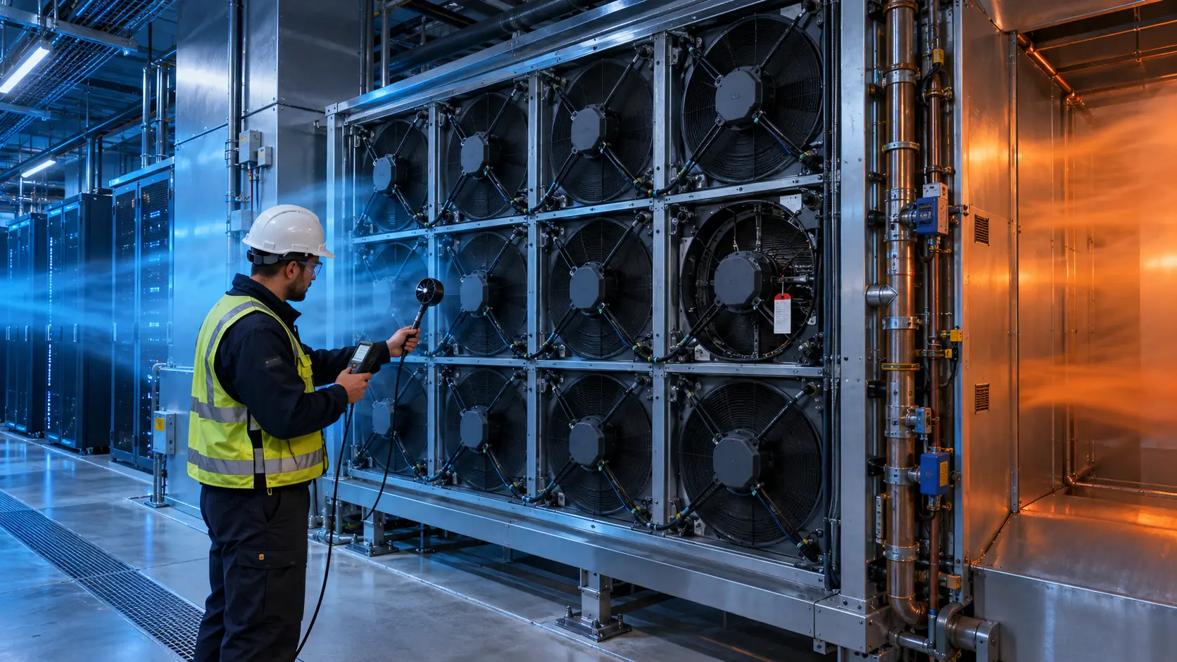
The team listed the array geometry, number of fans, spacing, blanking condition, inlet and outlet boundaries, heat load, pressure drop and control schedule. A fan wall, server tray and cabinet array can all use multiple fans, but their failure paths are not identical. A stopped rotor behind a check feature behaves differently from a completely open fan aperture.
The normal state and fault state were treated as two operating points. The team did not approve N+1 from a percentage such as five of six fans alone. That percentage can be a screening estimate, but the pressure curve, bypass, reverse flow, fan interaction and heat-load distribution determine the installed result.
| Input | Why it matters | Evidence |
|---|---|---|
| Protected load | Defines what must remain within margin | Server workload or battery heat state |
| Array geometry | Controls interaction and bypass | Fan spacing, blanking and plenum drawing |
| System resistance | Moves normal and fault operating points | Pressure and airflow curve |
| Failed path | Can divert flow backward through one module | Isolated-fan pressure and flow test |
| Recovery action | Sets speed, power and acoustic response | Command, current and thermal trace |
Measure the Normal Array Before Simulating a Fault
The baseline must include the installed restriction, because the failure comparison is meaningful only when the normal boundary is repeatable.
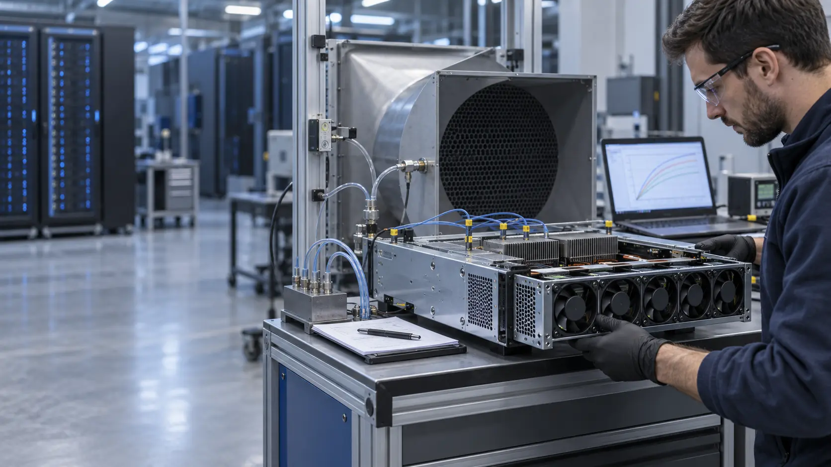
The array was tested with the production grille, filter where present, heat sinks, rack tray, coil or cabinet baffle and outlet. The record included fan voltage, current, command, actual RPM, airflow, pressure and temperatures. Measurements were made at more than one command so the normal array curve could be distinguished from a single point that happened to look acceptable.
The team recorded whether the fans shared a common plenum or had separate flow channels. It also checked whether one fan's discharge entered the inlet of a neighbor. Neighbor interaction can alter the pressure each fan sees and can make a catalogue fan curve unsuitable for predicting the array. A common enclosure can create a stronger coupling than the electrical control diagram suggests.
The normal baseline included idle, representative load and peak load. Acoustic and vibration observations were retained because the N+1 command may later push the remaining fans into a tonal or structural limit. A fault strategy that protects temperature but creates unacceptable noise or current still needs another design iteration.

Isolate One Fan Without Creating an Artificial Test
A fault simulation must represent the failed module that the system can actually experience.
The first test stopped one rotor while leaving the fan opening and its mechanical surroundings unchanged. The team then checked whether the stopped module allowed air to pass backward. A disconnected fan, a locked rotor, a removed module and an open blanking plate are different fault states and cannot be treated as interchangeable without evidence.
The pressure upstream and downstream of the failed module was measured with the remaining fans at normal command and at the intended recovery command. Airflow through the load path was measured separately from flow through the failed aperture. This identified whether the remaining fans were building useful pressure or simply circulating air inside the plenum.
The fault was repeated after the system reached a representative thermal state. A cold fault test can miss a control response that appears only after the inlet sensor crosses a threshold. The team also checked the power supply, fault signal timing and service state so the mechanical fault and controller response were not confused.
Recalculate the Array Operating Point After the Fault
When one module is unavailable, both the fan-array curve and the system resistance can change.
The remaining fans no longer saw exactly the normal plenum condition. The failed aperture changed local pressure and the array's combined curve. If the controller increased the remaining fan command, the new pressure could increase reverse flow through the stopped path rather than useful flow through the rack or battery modules. The candidate was therefore evaluated at the measured fault-state pressure, not only at its normal curve.
A simple equal-share estimate was retained only as a screening tool. For example, five available fans out of six might suggest 83 percent of normal capacity, but the installed result can be lower when the failed path is open, the system curve changes or the remaining fans operate at a different pressure. The estimate was not used as an acceptance value.
The comparison also separated pressure margin from total volume flow. A fan array may show a high internal flow while the heat-producing load sees less air because of bypass. The pressure taps and flow measurement locations were kept fixed so the change could be explained rather than hidden in a new test setup.
| State | Question | Required record |
|---|---|---|
| Normal | Does the array meet the installed duty? | Airflow, pressure, command and thermal trace |
| Fault | What is the new array operating point? | Remaining-fan pressure and load airflow |
| Bypass | How much air crosses the failed path? | Direction and magnitude at the aperture |
| Recovery | Does higher command restore useful flow? | RPM, current, noise and thermal response |
| Service | Can the module be replaced safely? | Access, connector, blanking and work instruction |
Check FG, RD and Controller Timing Separately from Airflow
A feedback signal can identify a rotor or wiring state, but it does not prove that the load receives useful airflow.
The controller response was logged from the moment the fault was introduced. FG or RD timing was compared with the measured rotor state, command change, current and pressure. This separated a stopped rotor, a missing feedback wire, a wrong polarity and an airflow restriction. Each can produce a different signal while the thermal consequence may appear later.
The system team defined what the fault output should trigger. In one application it could request a controlled increase in the remaining fans. In another it could derate the load or move the equipment into a service state. The fan supplier did not define that complete system action. The fan-side evidence showed when the signal changed and what airflow and pressure existed at that time.
The recovery command was tested for overshoot and supply limit. Sending every remaining fan immediately to maximum may restore some flow, but it can also trip the supply, create a large acoustic event or increase reverse flow. The acceptable command was chosen from thermal margin, current, pressure, noise and service requirements together.
Validate Acoustic, Vibration and Power Penalties in N+1
A fault strategy that preserves temperature but creates a new mechanical or electrical limit is not ready for release.
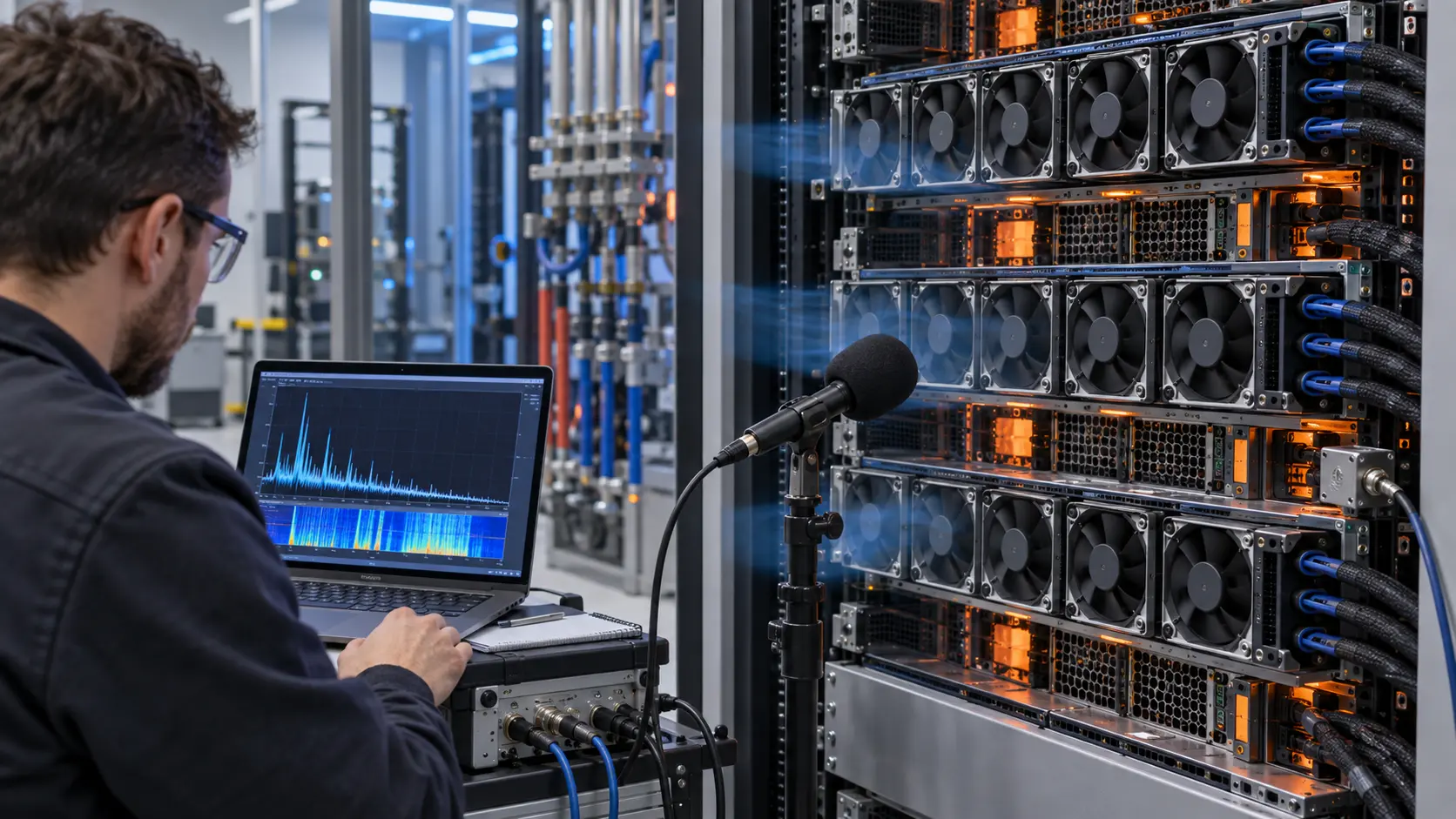
The remaining fans were swept through the normal and recovery commands while the failed path stayed in its controlled state. The team recorded overall sound, tonal peaks, vibration, current and temperature. Array interaction can produce a different acoustic result after one fan stops because the pressure field and neighbor loading have changed.
The mechanical review checked whether reverse flow caused a stopped rotor to spin, oscillate or transmit vibration into a bracket. It also checked whether the failed module became a whistle path through a grille or plenum. These observations matter for server rooms, energy-storage sites and any enclosure where service personnel or nearby occupants can notice the recovery event.
Power was measured for the normal array and fault-recovery command. The controller's energy budget included the remaining fan current, converter losses and any load derating. The result was documented as an application-specific tradeoff rather than a generic claim about fan-array efficiency.

Repeat the Fault at Hot Ambient, Loaded Filter and Service Conditions
N+1 evidence is incomplete if it is tested only in a clean, cool laboratory state.
The test matrix included warm inlet air, the defined load, filter loading where applicable and the service access condition. A loaded filter can reduce the pressure margin before the fault, leaving less capacity for the remaining fans. A warm inlet can also reduce the available thermal margin even if the airflow remains similar.
The team recorded whether the failed fan was isolated electrically, mechanically or through a controller command. It documented the blanking, connector and cable condition used for the test. Service staff need to know whether a failed module remains in the array until replacement or whether a safe temporary configuration is allowed.
The acceptance record distinguished a short bridge condition from a continuous operating state. Some equipment may tolerate a defined service window with reduced load, while another application may require immediate shutdown. The fan array can support that decision with evidence, but the system owner must define the permitted response.
| State | Risk | Evidence |
|---|---|---|
| Warm inlet | Thermal margin is reduced | Inlet and protected-load temperatures |
| Loaded filter | System pressure rises | Filter differential pressure and load airflow |
| Faulted module | Reverse path diverts useful flow | Direction and pressure at the aperture |
| Recovery command | Current or noise exceeds the limit | RPM, power, sound and thermal trace |
| Service state | Temporary assembly changes the path | Blanking, connector and work instruction |
Freeze the Array, Blanking and Control Specification
The N+1 release must describe the failed path and recovery behavior, not just the number of installed fans.
The release record captured fan envelope, quantity, spacing, airflow direction, plenum or tray geometry, filter and grille, voltage, current, PWM, FG/RD, alarm behavior, normal operating point and fault operating point. It also recorded the pressure and airflow measurement planes. The normal and one-fan-unavailable curves were kept together so a future change could be compared with the same boundary.
Change triggers included a new fan family, fan spacing, blanking plate, grille, filter, heat sink, coil, controller schedule, cable route, inlet temperature or service procedure. Any of these can change reverse flow and the remaining-fan operating point. The same number of fans does not guarantee the same N+1 result.
The service instruction showed how to identify the failed module, isolate it, preserve the airflow direction and replace it without changing the neighboring fan mounts. If a temporary blanking part is needed, its pressure and mechanical effects must be included in the evidence rather than treated as a harmless detail.
Result: N+1 Was a Measured Fault State, Not a Fan Count
The integrator gained a repeatable method for deciding whether a fan array protects the load after one module becomes unavailable.
The final package showed the normal array curve, the fault-state curve, the reverse-flow path, the remaining fan command, the protected-load airflow and the thermal response. It also recorded the feedback timing, supply current, acoustic condition, filter state and service configuration. This allowed the controls team to define a recovery command from evidence instead of assuming that maximum speed solved the problem.
The transferable result was not a universal airflow percentage. A six-fan array, five-fan array or larger fan wall can behave differently depending on plenum geometry, fan curve, failed aperture, load resistance and control logic. The relevant question is how much useful airflow remains at the protected load and pressure boundary.
A new rack, BESS cabinet, rear-door heat exchanger or fan wall should repeat the same sequence: define the protected state, measure normal operation, simulate the real fault, measure reverse flow, validate recovery and freeze the service boundary.
How MEGA Tech Supports Custom Fan Arrays
MEGA Tech helps rack and cabinet teams review fan-side airflow, pressure, controls and sample behavior around a defined array boundary.
MEGA Tech develops and manufactures custom cooling fans, covering fan selection, air-path review, sample validation and volume production. We can review DC axial fan candidates and centrifugal blower options for array spacing, pressure, airflow direction, voltage, PWM, FG/RD, connector, mounting, noise, vibration and environmental constraints. Where the system needs a custom sample, the N+1 state is part of the review rather than an afterthought.
For a first review, send the normal and fault heat load, airflow and static-pressure target, array quantity and spacing, fan envelope, voltage tolerance, control and feedback interface, filter or grille, failed-module condition, recovery command, acoustic target, environment, service method and quantity. Rack photos, cabinet drawings, pressure points or the existing fan model are useful starting evidence.
MEGA Tech is the custom cooling-fan manufacturer. Complete AI servers, BESS cabinets, fan-wall cabinets, coils, liquid loops, controllers, facility containment, emergency ventilation, electrical safety and system qualification remain with the equipment developer and system integrators. Start with the fan selection tool, review the DC axial fan range, or request an array sample review on WhatsApp.
Engineer FAQ
These questions usually decide whether an AI-server or BESS fan-array fault strategy is ready for release.
Q: Does five of six fans guarantee five-sixths of the airflow? A: No. Reverse flow, changed pressure and array interaction can reduce useful load airflow.
Q: Does FG prove that the rack or cabinet is cooled? A: No. FG indicates rotation. Measure installed pressure, airflow and protected-load temperature.
Q: Should the failed fan be removed? A: Not automatically. A removed module, stopped rotor and blanking plate create different pressure paths and must be tested separately.
Q: Should the remaining fans go to maximum speed? A: Test current, pressure, reverse flow, acoustic response and thermal benefit before choosing the recovery command.
Q: What should I send for a custom array review? A: Send array geometry, heat load, airflow, pressure, fan quantity, voltage, controls, fault state, recovery behavior and environment.
Questions for a Fan-Array Fault Design Review
Use this checklist with thermal, mechanical, electrical, controls, service and facility teams.
- What protected server, battery or power-electronics state defines the N+1 requirement?
- What airflow and static pressure are required at the actual load boundary?
- What is the normal array curve with the production grille, filter, plenum and heat source installed?
- Which physical fault is being simulated: stopped rotor, disconnected fan, removed module or blanking plate?
- How much flow crosses the failed path, and how much reaches the protected load?
- What voltage, PWM, FG/RD and alarm behavior occurs during the fault and recovery?
- Does the recovery command exceed current, noise, vibration or pressure limits?
- How do warm inlet air, loaded filters and service access change the fault state?
- Which geometry or control change triggers a new N+1 sample: fan, spacing, grille, filter, plenum or blanking?
- What exact information should accompany the sample request: size, voltage, airflow, pressure, quantity and environment?