A North American AI Integrator Found a Rack That Was Cooling Itself Twice
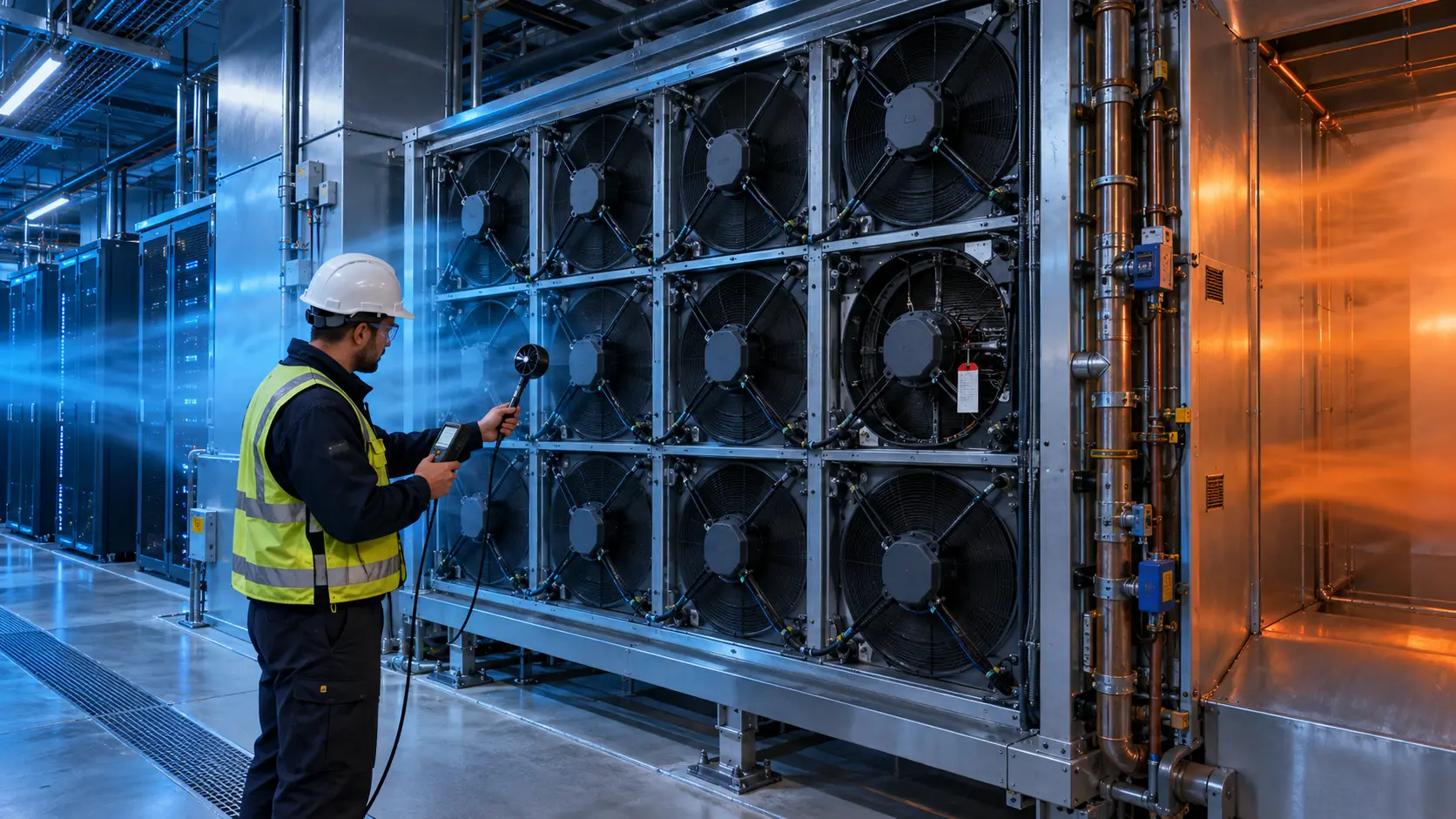
The rack had enough fan capacity on paper, but hot exhaust was returning to the server inlets before the control loop could react.
An anonymized North American AI-infrastructure integrator was commissioning a high-density rack for inference and storage workloads. The rack used front-to-rear server airflow, several removable fan modules and a room-level cooling system designed around a hot-aisle and cold-aisle arrangement. The average room temperature looked acceptable, yet the upper inlet sensors and two GPU zones repeatedly ran warmer than the rest of the rack.
The first reaction was to raise server-fan commands. That reduced the temperature briefly, but it increased acoustic output and auxiliary power without removing the cause. The commissioning team asked MEGA Tech to help separate three effects: insufficient fan pressure, cold-air bypass and hot-air recirculation. The customer name and released platform values are confidential; this case describes the sample-to-validation method.
The key lesson was simple: a fan can be operating normally while the rack is receiving the wrong air. A higher RPM cannot repair a hot exhaust path that returns to the inlet.

What the Engineers Had to Distinguish
Room temperature, rack exhaust temperature and server inlet temperature answer different questions.
The first measurement was rack-inlet temperature at several heights. A single room sensor could not reveal whether the top of the rack was receiving warmer recirculated air. The team logged inlet temperature, exhaust temperature, fan command, fan RPM, power and workload state at the same time. That made it possible to see whether the fan was responding to heat or merely chasing a contaminated inlet.
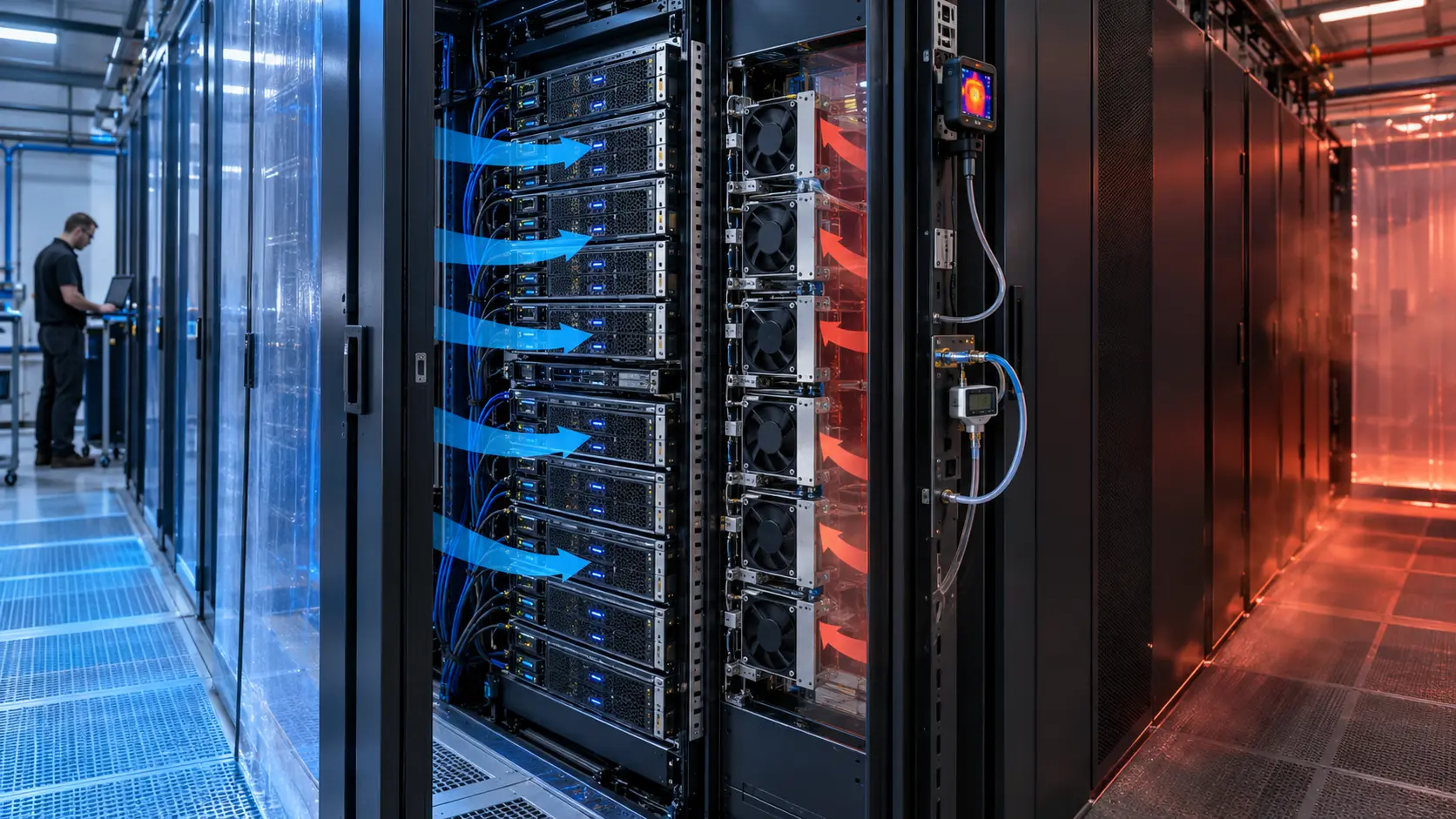
The second measurement was air-path direction. Smoke visualization, pressure taps and temporary temperature probes were used only as commissioning aids; the acceptance record relied on repeatable measurements. The team checked the rack ends, the top clearance, unused U-spaces, cable openings, the rear-door region and the interface between the server chassis and the fan tray.
The third measurement was pressure. The room supply, containment, rack openings and server fan modules form a connected system. If the rack is over-supplied, cold air can bypass the equipment. If the hot aisle is under-managed, exhaust can spill over the rack or around the row ends. Both conditions can make the return-air temperature look better while the server inlet is worse.
| Question | Measurement | Engineering decision |
|---|---|---|
| Is the inlet air inside the declared envelope? | rack-inlet temperature at top, middle and bottom | protect the hottest local zone, not the room average |
| Is air crossing the intended direction? | smoke check, pressure taps and temperature difference | seal or redirect before increasing fan speed |
| Is the server fan working at its installed point? | fan command, RPM, current and P-Q reference | select or tune the fan for the real restriction |
| Is containment helping? | inlet and exhaust temperatures with panels installed | confirm that bypass and recirculation are reduced |
| Does the condition survive a workload change? | idle, normal inference, peak and transition logs | validate the control loop rather than one snapshot |
The Initial Symptom Was Not a Fan Failure
The same fan RPM appeared normal, but the upper inlet temperature moved with the aisle and rack boundary conditions.
During the first run, the server fan modules reached the expected feedback speed. That result could have been misread as proof that the fans were healthy and the rack needed more cooling capacity. The temperature map told a different story: the upper inlet rose after the hot aisle reached a higher pressure, and it fell when a temporary top gap was covered.
A planning example showed the risk. If a 10 kW rack receives 20 °C air, a simplified air-side balance using 1.2 kg/m³ density and 1.005 kJ/kg-K specific heat gives roughly 0.83 kg/s for a 12 °C air rise, or about 2,500 m³/h. This is an engineering estimate for framing the test, not a universal rack requirement. If part of that flow bypasses the servers or hot air returns to the inlet, the useful cooling is lower even though the room airflow meter may look adequate.
The team therefore stopped treating the room airflow number as the rack result. It mapped where the air entered, where it crossed the server heat sinks and where it returned. This distinction also prevented an unnecessary fan upsizing decision before the installation was corrected.
Mechanical Review: Close the Shortcuts Before Changing the Fan
The rack had several small openings that were individually harmless but collectively strong enough to create a recirculation route.
The first revision installed blanking panels in unused rack positions and checked the seal around the removable fan tray. Cable openings were brushed or covered where they connected the hot and cold sides. The team also reviewed row-end containment and the clearance above the rack. The goal was not to seal every service opening permanently; it was to make the intended path stronger than the unintended path.
A second review checked equipment direction. Front-to-rear servers must be arranged so that neighboring equipment does not discharge into an inlet. Nonstandard airflow equipment needs a deliberate deflector or a separate zone. A rack can be correctly arranged at the row level and still have one shelf, switch or power unit that reverses the local flow.
After the mechanical changes, the server fan command was held constant. This isolated the benefit of the air-path correction from the benefit of any later fan adjustment. The inlet temperature became more uniform before the fan curve was changed.
Fan Selection Still Mattered After the Air Path Was Fixed
Containment cannot compensate for a fan that misses the installed pressure point, and a stronger fan cannot compensate for a leaking rack.
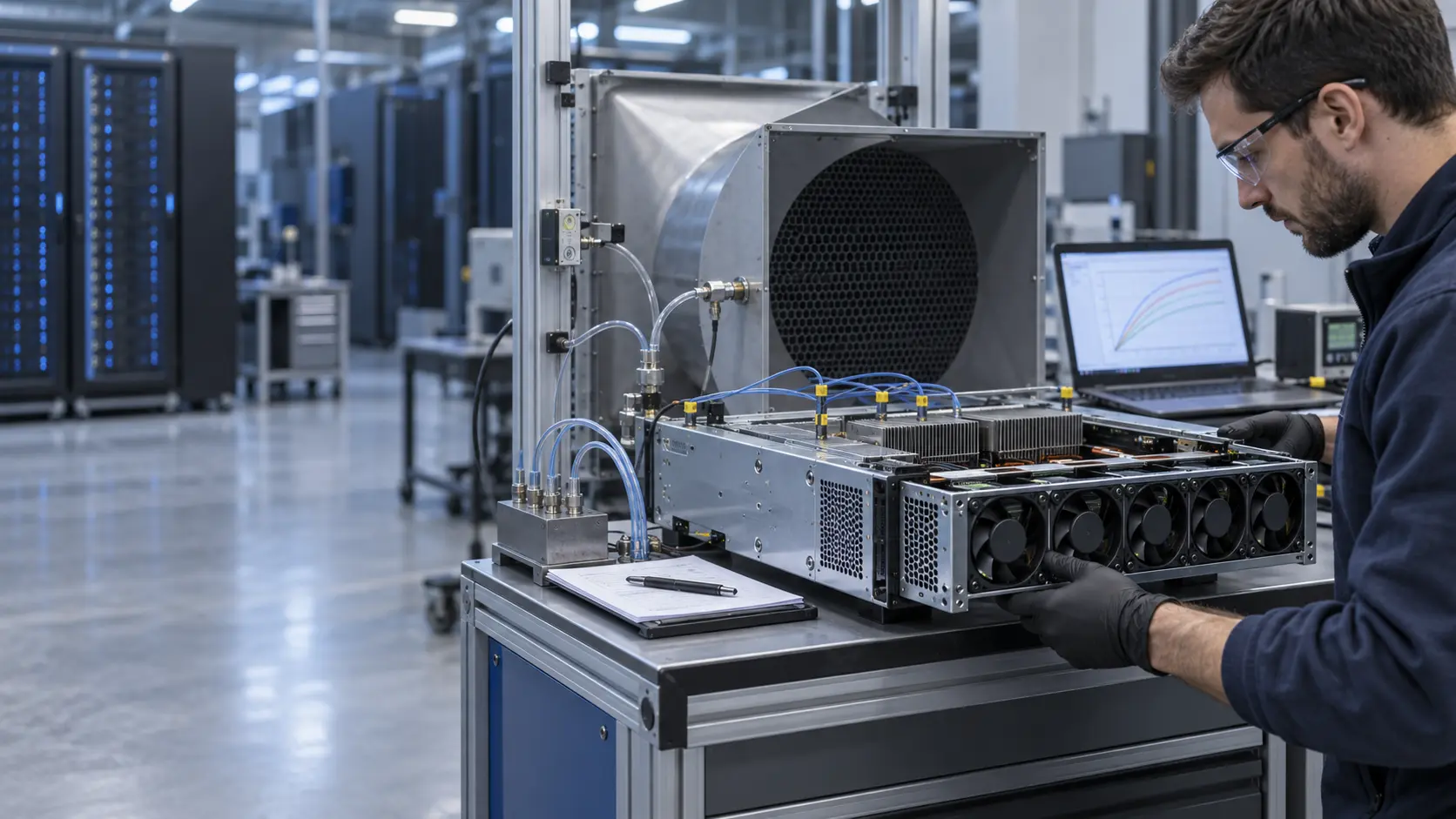
Once the airflow direction was controlled, MEGA Tech compared the candidate fan at the actual server restriction. The record included pressure or airflow at the tray, voltage range, PWM command, FG/RD behavior, current, noise and local heat-sink temperatures. The replacement was not accepted from a maximum CFM value alone.
The team used the fan P-Q curve and an estimated rack resistance curve to define the working point. For example, if a candidate is advertised at 60 CFM in free air but the tray and heat sinks require 8 mmH2O, the delivered airflow may be substantially lower. The exact result depends on the fan and system curves; the planning number must be measured on the actual tray.
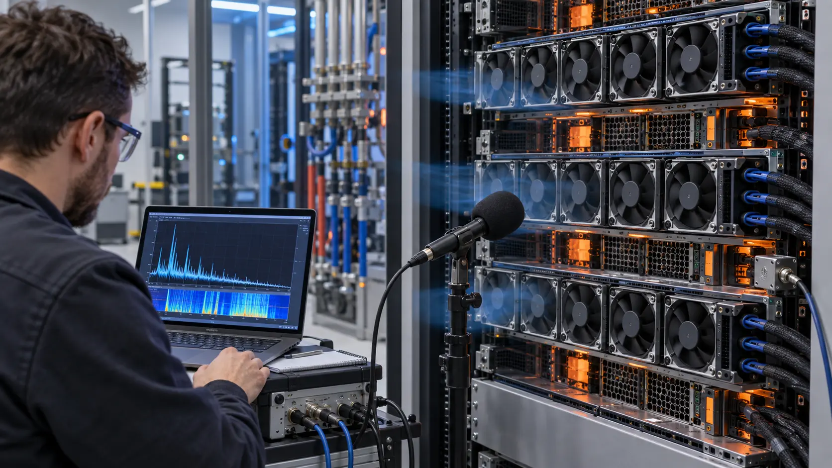
The sample review also considered control stability. If the inlet sensor is located in a recirculation pocket, the controller can increase RPM, overshoot and then reduce speed repeatedly. After the path was corrected, the control curve could be tuned around a cleaner signal. That reduced the temptation to use a permanently high command as a substitute for airflow management.
Validation Sequence: Prove the Rack at Three Workload States
The final check compared airflow direction, inlet temperature and fan duty during a repeatable workload sequence.
The customer used three states: idle or low utilization, representative inference, and peak compute. A fourth transition step moved heat from one zone to another so the team could observe the control response. At each state, the record captured rack-inlet temperatures at multiple heights, exhaust temperature, fan command, RPM, current and local component temperature.
The acceptance logic was based on the hottest protected inlet and component, not only the average. A planning example used a 5 °C maximum difference between the top and bottom inlet sensors after stabilization. That value is illustrative and must be replaced by the server maker's thermal budget. The important point is to define the location, time window and workload before testing.
The team repeated the sequence with the containment panel removed and reinstalled. That A/B check made the value of the installation visible to procurement and facilities teams. It also showed whether a fan change was solving the rack problem or simply masking a leak.
The Result Was a Stable Inlet, Not Just a Higher RPM
The integrator gained a repeatable commissioning method and a clearer fan requirement for the next platform revision.
After the openings and containment interfaces were corrected, the rack could be evaluated at a lower and more controlled fan command. The exact temperature, airflow and power values remain project-specific, but the engineering result was transferable: the customer could distinguish air-path loss from fan-capacity loss and could ask the fan supplier for the installed duty that actually mattered.
This also improved the purchasing comparison. A replacement fan had to match the server tray's pressure and control behavior while preserving airflow direction, connector, mounting and service access. If the customer later changed the grille or heat-sink stack, the operating point had to be rechecked; the fan number could not be copied blindly into the new configuration.
For a new AI server or a smaller integrator, the same process can start with one customer chassis and one removable tray. MEGA Tech can make a small sample, revise the fan around measured pressure and airflow, and support the evidence package before a larger production build.
How MEGA Tech Supports AI Rack Airflow Validation
MEGA Tech develops custom DC axial fans and compact blowers around the installed application, not around a catalogue headline.
We can review the fan frame and thickness, airflow direction, pressure and flow target, PWM or voltage control, FG/RD feedback, connector, cable exit, mounting, acoustic target, bearing configuration and the real grille or heat-sink restriction. For a server application, the most useful first input is the complete tray or chassis sample together with the workload, inlet-temperature limit and the current fan interface.
The development loop can include a baseline with the original fan, candidate samples, installed P-Q checks, inlet and exhaust temperature mapping, control response, noise and service-state validation. MEGA Tech can also support replacement development for widely used industrial fan platforms, but the server maker remains responsible for complete system approval, reliability, EMC, safety and data-center integration.
We do not present a fan sample as a substitute for a facility cooling design, liquid loop, rear-door heat exchanger or DCIM control system. Those systems require their own verified design. Our role is to help make the fan and its installed air path measurable and production-ready.
Engineer Questions About AI Rack Recirculation
Use these questions before approving a higher fan speed or a new fan supplier.
Q: Why can a rack have normal fan RPM but a hot inlet? A: RPM proves rotation, not that the air reaches the heat sink and exits through the intended path.
Q: Should the fan be upsized first? A: First check bypass, recirculation, blanking panels, row direction and containment. Then select the fan at the measured installed pressure.
Q: Does hot-aisle or cold-aisle containment always solve the problem? A: No. The choice depends on the room and service design; either approach still needs correct rack direction, sealed gaps and measured inlet conditions.
Q: What should be measured at rack level? A: Inlet temperature at several heights, exhaust temperature, fan command, RPM, current, pressure or airflow proxy, workload and local component temperature.
Q: Can this case be used as a guaranteed data-center performance claim? A: No. It is an anonymized engineering case pattern. The data-center operator and server maker must validate their own rack, room and safety limits.
Questions for an AI Data-Center Airflow Review
A short checklist turns a vague hot-rack complaint into a testable requirement.
- Is the server airflow front-to-rear, and are all adjacent devices aligned with that direction?
- Where are the top, middle and bottom rack-inlet temperatures measured?
- Are unused U-spaces, cable openings, tray edges and row ends sealed or intentionally managed?
- Does the rack have cold-air bypass around the equipment or hot-air recirculation into the inlet?
- What are the actual fan command, RPM, current and pressure or airflow at the installed tray?
- Which workload state produces the hottest local component?
- Does the fan control loop oscillate when inlet temperature changes?
- What changes when containment is removed, opened or restored?
- What happens during a fan fault, service event or temporary hot-swap?
- Which values belong to the fan supplier and which require complete server and facility validation?