A North American AI Integrator Had a Cool Rack With an Unacceptable Tone
The rack stayed within its thermal target, but a sharp fan tone appeared only after the complete tray was installed.
An anonymized North American AI-server integrator was preparing a dense inference platform. The removable fan tray passed the initial thermal check, yet operators reported a persistent high-pitched tone during the normal workload. The free-air fan result had not predicted it because the installed grille, heat sinks, tray and cable path changed the pressure and acoustic boundary conditions.
The customer did not want to reduce fan speed blindly. The platform still needed the same installed airflow, pressure margin, PWM response and fault behavior. MEGA Tech treated the original fan and the candidate as an installed-system comparison: same tray, same workload, same receiver position and the same thermal acceptance points. Customer identity and released product values remain confidential; this case describes the engineering process.
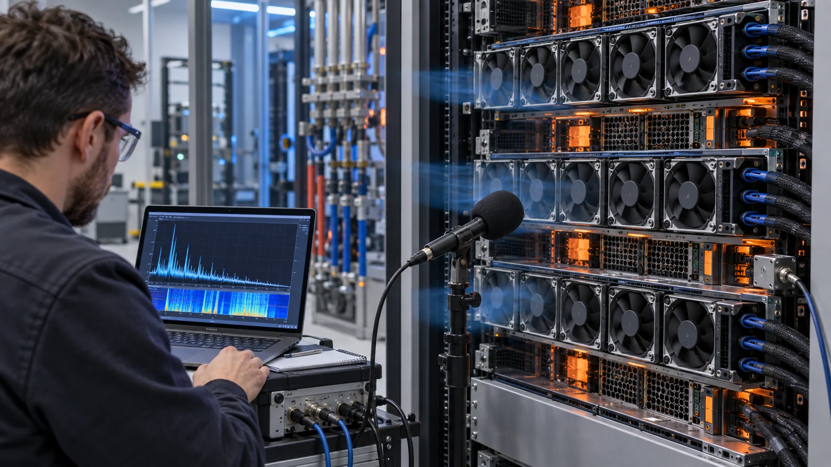
The First Comparison Was Misleading
A lower catalogue noise number did not guarantee a quieter installed server.
The first candidate matched the outline dimensions and showed a lower headline noise value in an open test. After installation, a narrow peak appeared at the normal controller command. The fan was not simply too loud; the sound had a tonal character that was more noticeable than the broadband level suggested.
The team calculated a first blade-pass estimate using blade count multiplied by RPM divided by 60. A seven-blade rotor at 4,800 RPM produces a first marker near 560 Hz. The estimate does not predict the final sound, but it helps correlate a spectral peak with rotor speed. The team then checked harmonics, speed variation, tray resonance and neighboring fans.
At the same time, pressure and airflow were recorded. A grille or heat sink can move the fan left on its P-Q curve, increasing blade loading and turbulence. This was why the acoustic report included installed pressure or airflow rather than only RPM and dBA.
| Evidence | Original fan | Candidate fan |
|---|---|---|
| Operating point | same tray pressure and airflow reference | same tray pressure and airflow reference |
| Control | PWM command, RPM and FG | PWM command, RPM and FG |
| Acoustics | dBA and frequency spectrum | dBA and frequency spectrum |
| Mechanics | tray vibration and mounting | tray vibration and mounting |
| Thermal | inlet and local component temperatures | inlet and local component temperatures |
Sample 01: Separate Airborne Noise From Tray Vibration
The customer needed to know whether the noise came from the fan airflow or from the structure carrying the fan.
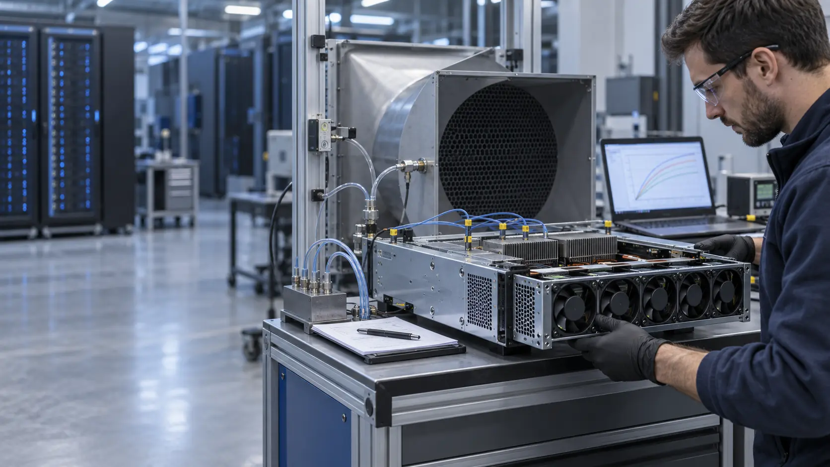
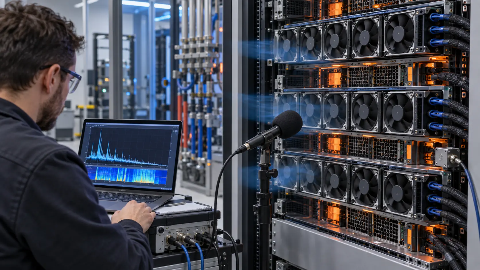
MEGA Tech first tested one fan on the bench, then in the tray, then in the complete rack. A microphone position was fixed for each comparison and an accelerometer was placed on the tray rail. The one-fan test isolated the source; the array test revealed interaction between neighboring fans and panels.
The tray showed a narrow vibration response near the candidate's normal command. The peak became stronger when the grille was installed, which indicated that the installation was part of the acoustic path. Mounting stiffness, fastener torque, clearance and seal condition were reviewed without allowing the fan to move or leak air.
This prevented the team from selecting a slower fan that would have reduced the tone by losing airflow. The solution had to preserve the installed duty while reducing the excitation or transmission path.

Sample 02: Tune PWM, RPM and the Acoustic Operating Window
The second sample was tuned around the controller and workload instead of being judged at one maximum speed.
The command was swept slowly through idle, normal inference and peak-compute ranges. The report recorded PWM, RPM, current, FG pulses, temperature, pressure or airflow and spectrum. This showed whether the tone followed rotor speed, appeared at one PWM band, or grew only after the tray restriction was added.
The candidate also had to start reliably at the lowest declared supply condition and remain stable at minimum duty. A different motor or driver can change the minimum startup command, the duty-to-RPM curve and the feedback timing. Those interface changes can create repeated restarts or an audible control whine if they are not validated with the server controller.
The customer defined a normal acoustic command, a peak command and a fault-recovery command. The fan was not accepted if it was quiet only during normal operation but entered a stronger tonal region during a thermal step or one-fan compensation.
Sample 04: Protect Thermal Margin While Reducing the Tone
The acoustic change was accepted only if pressure, airflow and temperature remained inside the same platform envelope.
The candidate was compared at the same installed pressure and workload. A planning example used a fan delivering 35 CFM at the declared pressure. If a quieter command reduced the delivered value to 30 CFM, the temperature effect had to be measured rather than assumed. With a 5 kW load and simplified air-side capacity near 1.2 kJ/m³-K, the lost flow can consume additional temperature margin; the actual result depends on density, bypass and heat-sink effectiveness.
The final candidate was not simply the fan with the lowest free-air dBA. It was the configuration that met the server's pressure and airflow duty, thermal limit, control interface, reliability requirement and acoustic target at the same installation. A custom blade, motor response, PWM window or mounting revision can be more valuable than selecting a slower catalogue fan.
The exact released noise, airflow and temperature values remain project-specific. The transferable result is the test method and the evidence required before a production change.
The Result Was a Controlled Replacement Path
The integrator gained a repeatable acoustic and thermal comparison instead of a subjective fan swap.
After the sample iterations, the customer had a defined normal command, peak command and recovery command, with the corresponding airflow, pressure, temperature, spectrum and vibration records. Procurement could compare the candidate against the original at the installed working point rather than relying on a single catalogue noise number.
The process also exposed the boundary between fan and chassis responsibility. If the tone changed after a grille, tray seal, panel or cable path changed, that was recorded as an installation effect. If the peak followed RPM or PWM with the installation fixed, the fan-side design became the next target. This made the next revision faster and reduced guesswork.
For a new AI server or a smaller integrator, MEGA Tech can build a small first sample around the customer's fan tray, control interface and acoustic target before larger production quantities are approved.
How MEGA Tech Supports Custom Low-Noise Server Fans
MEGA Tech develops custom DC axial fans and compact blowers around the real server duty and measurement condition.
We can review frame and thickness, blade and motor behavior, pressure/airflow duty, PWM or voltage control, FG/RD feedback, connector, cable exit, bearing configuration, mounting, noise target and the actual grille or heat-sink restriction. A candidate can be compared with the original in the customer tray rather than judged only by a free-air sound value.
For a first review, provide the current fan, complete tray or chassis, airflow direction, voltage range, PWM frequency and pinout, target airflow and pressure, acoustic measurement method, vibration concern, workload states, inlet condition, thermal limits and expected quantity. Include any N+1 or service state that changes the fan command.
MEGA Tech can provide a small sample and tune the fan-side behavior before production. The server maker remains responsible for complete acoustic, thermal, reliability, EMC, safety and platform approval.
Engineer Questions About This AI Server Fan Case
Questions to settle before approving a replacement or changing the fan curve.
Q: Why can a fan with lower dBA sound worse? A: A narrow tonal peak can be more noticeable than broadband noise even when the overall value is lower. Measurement method and receiver position also matter.
Q: What is blade-pass frequency? A: It is approximately blade count multiplied by RPM divided by 60. It is a diagnostic marker, not a complete noise prediction.
Q: Can changing PWM frequency remove the noise? A: It can change a driver or control tone, but motor behavior, EMC, thermal control and startup must be checked together.
Q: Why test the fan in the tray? A: Grilles, heat sinks, seals and panel resonance change pressure, turbulence and vibration transmission.
Q: Should all fans run at exactly the same RPM? A: Not always. A small validated offset can reduce beat tones, but only if airflow balance, redundancy and thermal margin remain acceptable.
Q: What does MEGA Tech need for a low-noise sample? A: The current fan and chassis, installed pressure/airflow target, voltage and PWM interface, acoustic method, mounting, workload, thermal limits, vibration concern and quantity.
Questions for an AI Server Acoustic Review
Use this checklist before freezing a fan replacement or approving a new tray.
- Is the acoustic value measured at the same installed pressure and airflow as the thermal test?
- Does the report include both overall dBA and a frequency spectrum?
- Does a peak follow RPM, PWM command, grille installation or panel vibration?
- Were one-fan and full-array conditions both tested?
- Are microphone position, bandwidth, weighting, workload and ambient conditions documented?
- Were fan current, FG/RD, startup, minimum duty and fault recovery checked?
- Does any acoustic change reduce delivered airflow or temperature margin?
- Are mounting stiffness, fastener torque, isolation and service access controlled?
- Which values are fan-side evidence and which require complete server validation?