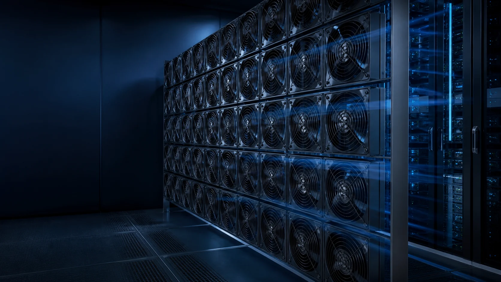
A fan wall is a system, not just a grid
A fan wall replaces one large air-moving component with a coordinated array of smaller modules.
In a data center air handler (CRAH, AHU or purpose-built cooling unit), a fan wall distributes airflow across multiple EC plug-fan modules rather than relying on a single large centrifugal fan. The modules operate in parallel: they share the same static pressure, and their airflow adds up. The wall acts as one air-moving system even though it contains several independent fans.
The arrangement exists to solve two problems a single large fan cannot. The first is failure blast radius: one big fan is a single point of failure whose loss takes the entire air handler offline, while a wall loses one small module and keeps most of its capacity. The second is serviceability: a failed plug-fan cartridge is a one-person, hot-swap exchange through the front of the wall, whereas a failed 30 kW centrifugal unit usually means rigging, downtime and a crane or a disassembly crew.
Modularity also changes the economics of capacity planning. Rooms grow in stages as racks are populated; a wall scales by adding cartridges to the array (or by specifying spare mounting positions up front), instead of committing on day one to the largest fan the vendor builds. The wall layout becomes a capacity plan, not just a mechanical drawing.
The energy case is worth quantifying the way operators actually budget it. As an engineering scenario, a 1 MW IT facility at PUE 1.5-1.6 has about 1.5-1.6 MW of total site power. If cooling represents 30-40% of site power and fans represent 15-25% of cooling power, the implied fan load is roughly 68-160 kW, before measurement and local operating conditions. A 30% reduction would save about 20-48 kW while that duty persisted. At $0.10/kWh and 8,760 hours, every sustained 1 kW is about $876 per year, so the same scenario represents roughly $17,700-$42,000 per year before controls, maintenance, demand charges and duty-cycle effects. That is a transparent estimate, not a universal payback claim; the running state, not the nameplate state, is where fan walls can win.
Acoustics can reward the array too, but there is no universal 3-6 dB advantage. The result depends on fan count, blade-pass tones, spacing, plenum geometry, operating speed, downstream attenuation and the measurement position. Many smaller fans at a lower individual duty may reduce tonal or low-frequency problems, while a poorly balanced wall can create additional noise. Reduced-speed operation generally helps, but the complete wall should be measured at the occupied boundary or the relevant equipment location.
The real objective is stable airflow at the served equipment, not an impressive sum of free-air fan ratings. Geometry, dampers and downstream resistance decide how evenly that capacity reaches the thermal load — so the wall, plenum and coil must be designed together. Reviewed as separate line items by different trades, they will optimize themselves into an uneven, noisy array; reviewed as one system, they behave like a single, well-behaved fan.

Why N+1 actually works (and when it does not)
Parallel fans add airflow at the same pressure; redundancy is the spare capacity to cover a stopped module.
Fans in parallel share the system pressure. If one stops, the system curve does not move, so the remaining fans must each move more air and the combined operating point changes. Whether that change is acceptable depends on the complete fan-array curve, system resistance, control limits, inlet conditions and any backflow through the failed module. Fan count alone cannot prove N+1.
The margin comes from headroom. In an ideal equal-sharing calculation, a 12-fan wall with one module unavailable loses 1/12, or 8.33%, of nominal capacity before the controller changes speed. That does not mean each fan should always be selected at 80-90% of maximum airflow: 80-90% is only an early engineering heuristic, and the actual N+1 point must be solved on the measured fan curve, system curve and maximum-speed limit. The surviving 11 fans may need to move more air and pressure than they did in the nominal case.
Read that against a per-fan curve rather than a datasheet headline. The surviving fans climb their speed as the controller compensates, and the honest question is whether the required duty point still sits on the stable part of each curve — below the surge region and inside the motor's thermal envelope. A wall that passes the nominal case but surges when one module fails has redundancy on the label only.
One detail decides whether the loss is even that small: a backdraft damper on every fan, or another verified isolation strategy. Without it, air can recirculate through the dead module and the array can lose materially more than the simple 1/12 arithmetic suggests. The additional loss is system-dependent, so check it physically at the design pressure rather than copying a generic 10-20% penalty into the specification.
Finally, confirm the failure is survivable in operations, not only in theory. How is a stopped module detected, how fast can it be swapped, and does the swap require shutting down the wall? A hot-swap cartridge with a shelf of spares turns N+1 from an arithmetic claim into a maintenance routine.
Redundancy is a degraded-state requirement, not a label
Tie 'N+1' to a documented condition the system has actually been validated against.
Redundancy should be evaluated under the conditions the system will actually face: what airflow, pressure and component temperature remain if a module is unavailable, if a filter loads, or if one zone becomes more restrictive than expected. This turns N+1 from a marketing label into an engineering requirement. Write the acceptance criteria as numbers: 'with one module out and filters at final pressure drop, the wall still delivers X% of design airflow and the served zone stays below Y°C'.
Filter loading deserves special attention because it moves the system curve slowly and silently. A wall commissioned on clean filters passes its test, then spends months drifting toward a condition nobody measured. Validate the loaded-filter case explicitly — with artificial resistance if the filters are new — and put a pressure-difference alarm on the bank so the degraded condition announces itself.
Availability targets should be translated into a documented fan-wall degraded state rather than mapped to a label automatically. A design that requires concurrent maintenance must allow one module to be removed while the rest carry the load for the required service interval. That forces the headroom, damper and control questions to be answered for an indefinite degraded state — not a sprint until the spare arrives. If a project uses Tier II, Tier III or Tier IV terminology, keep the availability target and the fan-wall acceptance test explicit instead of assuming the tier name proves the cooling design.
The minimum acceptable condition for the tier you are targeting must be documented and validated before the unit is accepted. A handover package that contains only nominal-state measurements has not validated redundancy; it has validated the easy half of the design.
The one-module-out acceptance test
A credible N+1 claim is a measured acceptance condition, not a fan count on a submittal.
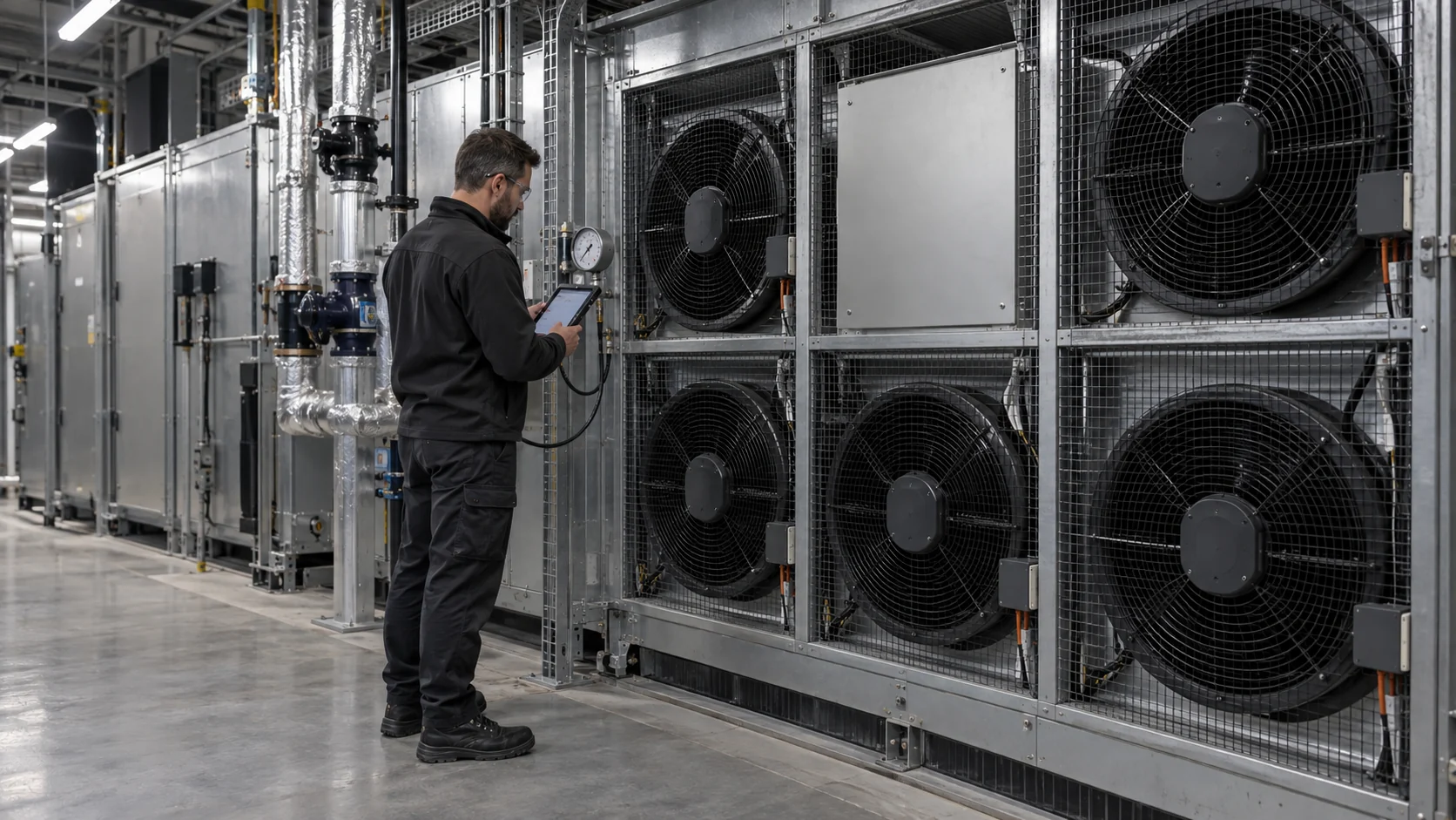
For the fault test, operate the wall with representative coil, filter, grille and downstream resistance. Stop or isolate one module at the design load, allow the controller to reach its permitted response, then measure total airflow, differential pressure, fan speed, electrical input and the temperature at the served zone. Repeat at the specified loaded-filter condition if that is part of normal maintenance life.
The critical observation is not whether the remaining fans spin faster. It is whether their combined operating point remains within the fan, motor, acoustic and thermal limits while the served equipment remains inside its temperature envelope. Parallel-fan guidance also makes the isolation issue explicit: a stopped fan without an isolation damper can become a reverse-flow path, so the condition must be tested with the actual damper and leakage behavior.
ASHRAE treats untested failure combinations as a commissioning risk. For a fan wall, the handover record should therefore include the normal state, the loaded-resistance state and the one-module-out state, with the relevant alarms and recovery behavior. That record is useful again when a replacement module is installed months later.
| Test state | Measure | Pass criterion set by the project |
|---|---|---|
| Normal duty | Airflow, pressure, fan speed, power and served-zone temperature | Establishes the baseline at the specified load and resistance. |
| Maintenance-limit resistance | Same readings with filter/coil resistance at the defined service condition | Shows the wall does not rely on a clean-only operating point. |
| One module unavailable | Remaining capacity, backflow/isolation behavior, alarms and response time | Proves N+1 at the actual operating pressure. |
| Module replacement | Control map, alarms, rotation, speed and post-swap distribution | Confirms a spare can return the wall to its documented baseline. |
Plenum geometry controls distribution
A rectangular arrangement does not automatically mean uniform airflow.
Air does not become even simply because the fans sit in a rectangle. Plenum depth, wall clearance, grille open area, internal obstructions and downstream openings all shape the flow map. If one part of the wall has an easier inlet or discharge, those modules take capacity away from a hotter zone — often invisibly from the front of the wall.
Maldistribution announces itself in per-fan telemetry before it reaches the room. Fans working harder than their neighbours draw more current and report higher speed for the same command; comparing those values across the array is the cheapest maldistribution detector you own. If one corner consistently runs 10% faster than the rest at a common setpoint, the geometry — not the fan — is the finding.
There is no one module-spacing multiplier that transfers safely across every plug fan, inlet bell, guard and plenum. The defensible rule is to follow the selected fan supplier's installation guidance, then verify inlet uniformity and module-to-module loading in the assembled wall. Nearby walls, guards, dampers and abrupt transitions can create system effects that do not appear in catalogue ratings.
Use the physical arrangement to suppress short-circuit paths so every fan sees comparable resistance. Open plenum sections, missing blanking panels and oversized return paths let air choose the easy route; balance dampers, baffles and deliberate section geometry force it through the coil and the served zone evenly. Where the layout is tight, a CFD pass or a physical flow-hood survey of the discharge face is a worthwhile purchase — it is far cheaper than rework after the room is live.

Control and monitoring need coordination
A multi-fan system needs one speed plan, clear fault behavior and per-fan visibility.
A module running at the wrong speed, or installed incorrectly, changes distribution across the whole assembly. Define a single speed setpoint (typically one 0-10 V or Modbus command to all fans) and let the controller coordinate them. Resist the temptation to hand-trim individual fans to fix a distribution problem — the trim hides the symptom while the geometry cause remains, and the next firmware update or module swap unmasks it.
Modbus is worth the wiring because it returns alarm, speed and power per fan into the BMS or DCIM. With per-fan current history you can trend bearing wear, spot a loading filter as a slow rise in group speed, and verify after every module replacement that the new unit lands on the same operating point as its neighbours. Without per-fan visibility, a fan wall is several hundred watts of blind capacity.
Define normal, reduced-capacity and alarm states before commissioning, and make it possible to detect a loss of capacity early rather than waiting for a room-temperature alarm. A dropped module should raise an alarm within seconds — tach signal loss makes this easy — and the event should state how much capacity remains, so the operations team knows whether they are in N+1 or N.
One operational advantage of EC walls: soft-start ramping removes the simultaneous inrush that a bank of AC induction fans can draw on restart — which has been known to trip upstream protection. An EC wall restarts in seconds instead of minutes. Coordinate the restart deliberately anyway: after a power event, a staged ramp with a short delay between groups keeps the transient small and gives the BMS time to verify each stage before committing the next. On the supply side, give every module its own fuse and size the feeder for a simultaneous restart of the whole wall — EC inrush is gentle, but a dozen modules recovering at once is still a coordinated event the electrical design should expect.
A final operational nuance: at low load it can be tempting to switch modules off and let the rest carry the duty. That saves energy only when the system pressure and fan efficiency maps support it; against coils and filters, running every fan slowly may be the better compromise. Compare both strategies using measured input power at the same total airflow and pressure, not the number of modules that happen to be enabled.
Commission with representative resistance
An open-wall test proves rotation; it does not prove the operating point.
Fan-wall testing should include the final grilles, filters, coils and any downstream equipment. An open-wall run is useful for checking rotation and basic function, but it does not validate the operating point because the real system resistance is absent — the fans will look strong and quiet, and tell you nothing about how they behave at kilopascals.
Measure temperature and pressure at locations that represent the served equipment, and where practical, test the fault scenario instead of extrapolating it from a nominal case. A wall that meets spec on a clean coil can fall short once a filter loads or one module is out — exactly the condition redundancy is meant to cover.
Three commissioning tests cover most of the risk. First, the nominal case at design airflow: verify total flow and room distribution. Second, the loaded case: filters at (or artificially loaded to) final pressure drop, confirming the wall still reaches duty within acoustic limits. Third, the fault case: stop one module at representative load and record what the room actually does — time to converge, remaining capacity, alarm behavior. A fault rehearsal during commissioning costs an hour; discovering the same gap during an incident costs a P1.
Document all three as the acceptance baseline. Later comparisons — is this wall degrading, was that module swap clean — are only meaningful against a recorded starting point, and the baseline is what turns anecdotes about 'the fans seem louder' into engineering decisions.
Develop the module around the wall's real duty
A reliable fan wall starts with a defined module requirement, then proves that requirement in the actual airflow system.
Fan-wall builders and data-center equipment teams often need more than a standard motor and impeller. The module has to match the wall opening, plenum, coil or filter resistance, voltage, control interface, acoustic limit, service method and redundancy plan. MEGA Tech can work from those system requirements and help convert them into a practical custom fan specification for evaluation.
The review can include fan size and thickness, airflow and static pressure at the loaded operating point, speed range, PWM or 0-10 V control, FG or alarm feedback, connector and cable details, rotation direction, bearing selection, mounting and environmental protection. Where the standard configuration misses the required combination, we can adjust the module and build a sample for the customer's wall or representative test fixture.
Validation should use the real grille, filter, coil, plenum and controller wherever possible. We check total airflow, pressure margin, module-to-module balance, noise, temperature rise, control response and one-module-out behavior. After the customer approves the sample, the specification can move into repeatable volume production with consistent configuration and a lower-cost alternative to expensive imported fan assemblies.
- Define the wall's airflow, pressure, redundancy, noise and service targets.
- Customize the module's electrical, mechanical, control and mounting details.
- Test the sample against representative resistance and one-module-out conditions.
- Transfer the approved module into stable, repeatable production.
Keep capability statements precise
This article explains a facility-cooling category; it is not a MEGA Tech fan-wall announcement.
The engineering lesson holds regardless of vendor: design the wall as one thermal system, size each module with headroom, damp every module, and validate the degraded state. When you evaluate a specific wall, ask for the measured per-fan curve at your system pressure, the headroom and damper strategy, the control interface, the required IP rating for the actual location, the fault behavior, and the spares and firmware policy so a replacement needs no reconfiguration.
The firmware point is easy to skip and annoying to learn the hard way: in a mixed-age array, a replacement cartridge with newer firmware should drop in and behave identically — same curve response, same alarm codes, same Modbus map. Ask the vendor to state that compatibility commitment in writing, and keep at least one configured spare per critical fan size or a documented replacement lead-time plan. A 5% spare-stock rule is sometimes used as a starting point, but it is not a reliability standard; the right quantity depends on fleet size, failure rate, lead time and the required degraded state. Treat the damper, connector and control map as part of the spare module, not as separate details.
Market context helps when comparing proposals, but it should not replace a curve set. Six to twelve modules per unit, an 8-12% capacity reserve, and 500-630 mm backward-curved EC plug fans are useful proposal ranges seen in some facility designs, not universal standards. Backward-curved impellers are often selected for this duty because their efficiency and pressure behavior can suit variable-load air handlers, but the actual peak efficiency and stable operating range depend on the impeller, motor, casing and control. Verify any specific wall against the same measured data you would demand for a single-fan unit.
Engineer FAQ: Fan Wall Redundancy and Airflow Validation
A fan wall earns its redundancy claim only when airflow, pressure, distribution, controls and maintenance are proven in the degraded state.
Q: Does N+1 mean the wall can always lose one fan without impact? A: No. N+1 is a defined capacity and availability requirement. Confirm the remaining fans can meet the required airflow and pressure with one module unavailable, the filter at its maintenance-limit pressure drop and the control system at its allowed speed limit.
Q: Why can a failed fan reduce more capacity than its own share? A: Without a backdraft damper or another verified isolation method, the stopped module may become a low-resistance reverse-flow path. The actual loss depends on the fan, pressure and plenum, so measure it at the design duty instead of applying a generic penalty.
Q: Do parallel fan modules simply add their individual CFM ratings? A: No. The array operates on a combined fan curve against the system curve. Plenum geometry, inlet clearance, spacing, downstream resistance, fan-to-fan interaction and control limits can reduce the installed result compared with the sum of free-air ratings.
Q: Should every module run at the same speed command? A: A common coordinated command is usually a better starting point than manual per-fan trimming, but it does not fix uneven geometry. Compare module speed, current, power and alarms, then correct the plenum, baffles or dampers before hiding maldistribution with individual offsets.
Q: How should filter loading be included in commissioning? A: State the clean pressure drop and the final maintenance-limit pressure drop, then test both or add calibrated resistance to represent the loaded condition. Record total airflow, discharge distribution, pressure, temperature, fan speed and power, and define the alarm threshold for rising filter resistance.
Q: What does hot-swap actually need to prove? A: Demonstrate that one cartridge can be removed and replaced without violating the required thermal condition, and verify the replacement has the same electrical, control, alarm, firmware and performance behavior. The spare module, damper, connector and configuration data should be treated as one serviceable assembly.
Q: Is a fan wall automatically more energy efficient than one large fan? A: Not automatically. Savings depend on the duty profile, fan efficiency map, system resistance, control strategy, coil condition and whether modules are staged or slowed. Compare measured input power at the same delivered airflow and pressure, including normal and degraded operation.
Q: When should a custom fan module be considered? A: When the wall opening, voltage, pressure, airflow, acoustic limit, control interface, mounting or service requirements cannot be met together by a standard module. Validate the customized sample in the representative plenum, coil, filter and fault condition before volume production.
- Tie every numerical answer to voltage, speed, temperature, mounting and test condition.
- Separate catalogue maximums, engineering estimates and measured application results.
- Use the FAQ to define the next measurement or sample-validation step.
Engineering checklist
Review the assembly as one thermal system, normal and faulted.
The list below keeps a fan-wall decision honest: capacity is only useful if it survives the conditions the unit will actually see.
- Capacity in normal and degraded operating states (one module out, filter loaded)
- Concurrent-maintenance procedure: can one module stay out indefinitely at the target tier?
- Module spacing, inlet clearance and replacement method (hot-swap, one-person)
- Backdraft damper on every fan; plenum geometry and downstream restriction
- Headroom: use 80-90% only as an initial heuristic, then solve the N+1 point on measured curves
- Speed-control, alarm and per-fan monitoring behavior (0-10 V or Modbus)
- Staged-restart behavior after a power event; firmware compatibility across cartridge ages
- Temperature and pressure validation under representative load, including a fault test