A Fan Alarm Is the Start of Diagnosis
A BMC alarm identifies a condition; it does not by itself prove the airflow path is restored.
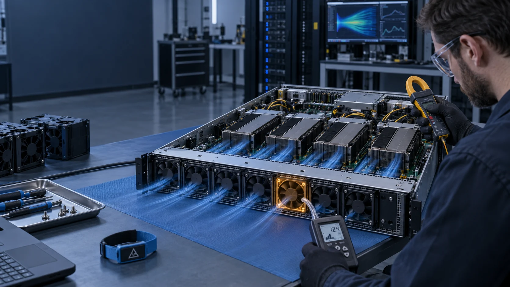
NVIDIA service guidance identifies a failed fan module through three independent views: BMC sensor telemetry, the operating-system health tool, and a physical module LED. All three have to agree before hardware is touched, and the replacement is then confirmed through the same three views. That triple-check sequence is platform-specific in its detail but universal in its logic, and it is worth copying even on hardware where no such manual exists.
Before any module is removed, capture the state that the alarm fired in: module identity and bay number, alarm type and timestamp, commanded PWM duty, reported RPM for every module in the array, inlet temperature, and the temperatures of the components that module serves. A photograph of the BMC sensor screen is a legitimate field record. Without this snapshot, the post-replacement comparison has nothing to compare against.
A normal RPM confirms that a rotor is turning. It cannot confirm that useful air is reaching a loaded heat sink. A blocked inlet, a cable routed across the duct, an inverted module, a partially collapsed filter or a failed neighbour that has turned a bay into a return path can all leave reported speed looking plausible while delivered cooling duty is wrong. Pair fan telemetry with inlet temperature, component telemetry, and wherever practical a pressure or delivered-airflow check.
Alarm naming differs across platforms — one vendor may log a fan fault as a numeric event code while another exposes named sensor states such as lower critical or lower non-recoverable thresholds. The letters do not transfer between vendors. The sequence does: confirm which bay, confirm what the management path believes, confirm what the air path is actually doing, then decide whether the fix is a module, a duct, a filter or a control setting.
What the BMC Can and Cannot Prove
Fan telemetry proves rotation, command tracking and the health of the management path — nothing more.
A baseboard management controller earns its value by making cooling observable. Depending on the platform, it can report per-module RPM, the PWM duty the controller believes it has issued, module presence and identity, and on some designs input current or a chassis differential pressure. Those readings are what makes N+1 redundancy verifiable at all: without a per-bay RPM channel there is no way to know that a module is missing until a thermal alarm fires.
The limit is that almost everything the BMC reports is an electrical or rotational quantity. Duty cycle is a command, RPM is a rotor measurement, and current is a motor measurement. Delivered airflow is none of those things. It depends on impeller condition, the resistance of the duct, the direction the module was installed, and the behaviour of neighbouring modules. A control loop that has been tuned against RPM alone will happily hold a wrong airflow at a correct speed.
Threshold design deserves the same scrutiny as sensor selection. A fan alarm set only at a zero-RPM locked-rotor condition will miss a module that has slowed by a third because its bearing is failing, and it will miss a module whose airflow has collapsed behind a blocked duct while the rotor spins faster than usual against the restriction. Where the platform exposes a lower critical threshold, set it relative to the commanded duty rather than as a single absolute number: a module commanded to 40% that reports 40% is healthy, and a module commanded to 100% that reports 62% is not.
The practical conclusion is that the BMC is a fast, cheap and continuous indicator of the electrical half of cooling, and a poor indicator of the aerodynamic half. Use it to detect change and to trigger investigation, then confirm with temperature and, where the risk justifies it, with a delivered-airflow or pressure measurement.
Redundancy Is a Speed Reserve, Not a Spare Part
N+1 works only because the surviving modules have somewhere to go when one stops.
The instinct is to read N+1 as 'one spare fan'. That reading produces designs that fail the first real fault. The correct reading is that the array is sized so the remaining modules can absorb the loss, which means the healthy state must deliberately run below maximum. The common industry practice is to operate working modules around 70% of maximum speed and hold roughly 30% speed headroom specifically for fault compensation, then have the controller ramp every survivor toward 100% when a bay drops out.
The compensation is not marginal. Reported field behaviour for 2U platforms shows surviving modules being driven up by roughly 20 to 40% in speed to cover a single loss, and the controller has to do it quickly enough that the heat sinks never see the deficit. Two consequences follow. First, the reserve has to be validated with a module actually removed or stopped, at worst-case load and worst-case inlet temperature — a model is not an acceptance test. Second, once the reserve is spent there is no second fault margin left, so the alarm that announces the failure is also announcing a deadline.
That deadline is expensive in three currencies. Acoustic output rises roughly with the fifth power of rotational speed, so a sustained ramp to full speed is far more than a proportional noise increase. Motor and bearing load rise, and the life model that applies to a module running at 70% is not the model that applies to one held at 100%. Auxiliary power draw rises at the same time, which matters in installations where fan energy is metered separately. Redundancy is therefore not free availability — it is availability purchased at a known steady-state cost, and the design should say so explicitly.

| Configuration | What it tolerates | Typical use |
|---|---|---|
| N | No failure. Any module loss reduces cooling below requirement | Non-critical enclosures, lab benches |
| N+1 | Any single module failure, at full load | Servers, telecom cabinets, BESS HVAC |
| N+2 | Two simultaneous failures | Remote or unmanned sites where service takes days |
| 2N | One complete array lost | Mission-critical and defence installations |
Backflow Turns an Idle Module into a Leak
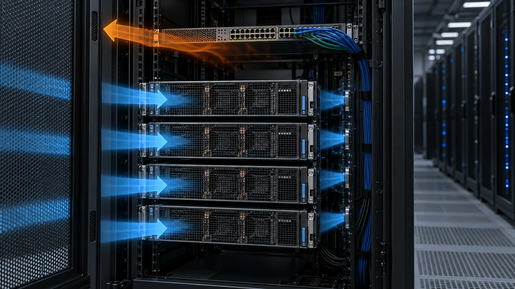
A stopped rotor is an open hole in the air path, and air will use it.
Modules in a server array sit in parallel, and parallel paths share the same pressure difference. When one bay stops moving air, it presents the lowest resistance in the chassis, so a fraction of the air being pushed by the survivors returns through it instead of crossing the heat sinks. This is the mechanism behind a fault that looks thermally impossible at first inspection: the array is running at full command, the alarm has cleared, and a downstream component is still hot.
The effect is local, which is what makes it hard to see. Chassis-level airflow can be within tolerance while the region immediately downstream of the idle bay starves. Survivors also move to a different point on their pressure-flow curve when the system resistance changes, so the delivered flow per module is not simply the healthy figure divided by the number of working modules.
Mechanical and electronic answers both exist. Gravity or spring-actuated louvers and back-draft dampers close when a bay stops moving air, which addresses the path directly and works without any control action. Where shutters are not practical, the controller strategy is to overdrive the survivors enough that the pressure difference across the idle bay reverses only briefly, and to use the module's rotation-detection or locked-rotor signal as the trigger rather than waiting for a temperature alarm. Detection should be treated as a control input, not as a notification.
Validate the condition rather than assuming the mitigation works. With the failed module still in place and stopped, probe for reverse flow at that bay — a vane anemometer held at the idle aperture will often show the direction clearly enough — and compare the temperatures of the components downstream of the idle bay against their accepted limits. If the chassis depends on the survivors being commanded to full speed within a few seconds, the command latency is part of the acceptance criteria too.
Replacement Validation Has Four Checks
Mechanical fit, electrical behaviour, airflow duty and management visibility must agree before a replacement is accepted.
Treat a check as failed if the evidence for it does not exist. A replacement module that fits, spins and clears the alarm has passed two checks and produced no evidence for the other two, which is exactly the state in which a second, slower fault can hide.
| Check | Record | Why it matters |
|---|---|---|
| Mechanical | Frame, thickness, airflow direction, latch and service access | A correct connector does not prove a correct air path |
| Electrical | Voltage range, inrush current, connector, PWM, FG/RD and restart behaviour | Avoids control or protection faults after the swap |
| Thermal | Inlet temperature, key component temperatures and pressure or delivered-flow evidence | Shows installed cooling duty, not just rotation |
| Management | BMC module identity, alarm clears and actual-speed status | Makes the replacement supportable in service |
The Service Window Is a Design Parameter
How long the chassis survives with one module missing is a specification, not a hope.
The 30-second replacement window stated in NVIDIA's DGX A100 fan procedure is the clearest published example of a service constraint being treated as part of the thermal design. It is not a general rule, and it is not a target that other platforms should borrow. It is a consequence of that chassis's thermal mass, its airflow layout and the workload the system was running. What matters is that somebody measured it and wrote it down.
Most installations have no equivalent number. The result is that fan replacement is scheduled by whoever is available, and an array that has been running on its reserve for three days is treated as normal. A better practice is to derive the number and publish it: take the chassis at its worst-case load and worst-case inlet temperature, remove or stop one module, and measure how long component temperatures take to reach their limits with the survivors at full command. That duration, minus an engineering margin, is the service window.
The number then feeds three decisions. It sets the alarm priority — a fault on a design with a 40-minute window is a scheduled maintenance task, while the same fault on a design with a two-minute window is an emergency. It sets the spares policy, including whether on-site stock is required. And it belongs in the acceptance test, because a replacement procedure that cannot be executed inside the window has not been validated, however well the module performs.
Interactive: BMC Alert to Thermal Recovery
Use the stages below as a validation record, not as an automatic approval process.
The model below visualises three states: normal loaded duty, one module unavailable, and replacement with restart. Walk through them in order and ask whether the management path, the survivor response and the post-replacement thermal evidence all tell the same story. The point of the exercise is to find the state where they disagree, because that is the state that turns into an unplanned outage later.
Control Behaviour After Replacement
A module that works on its own may not work in the array it has joined.
Two modules with the same frame size, the same voltage and the same nominal speed can still have different speed-versus-duty curves. When one is significantly steeper than its neighbours, the controller commands the same duty to all of them and gets a different speed from each. In a healthy array this is invisible. During a fault ramp it becomes visible quickly, because the module that reaches full speed first is the one that sets the acoustic and current peak while its slower neighbour is still catching up.
Rotation feedback has the same problem in a less obvious place. Tachometer and rotation-detection signals are not standardised across manufacturers: pulses per revolution, output polarity and open-collector versus push-pull drive can all differ. A replacement that is mechanically and electrically correct but presents a different tachometer characteristic can be read by the BMC as a healthy module reporting a wrong speed — and a wrong speed reading is worse than no reading, because the control loop will act on it.
The practical safeguard is a short control-loop test after any replacement. Command the array through a full-speed sweep, a return to the working duty and a steady-state hold, and log per-module RPM alongside the command. The array passes if every module tracks the command with a similar shape and none of them oscillates, hunts or lags persistently. Then repeat the check with one module stopped, so the survivor ramp is exercised rather than assumed.
Specify Life for the Actual 24/7 Duty
An L10 figure belongs with its temperature, voltage, orientation, speed and test assumptions — never on its own.
AI workloads hold compact fans at elevated speed for long periods, which is precisely the condition that shortens bearing life. Published L10 test methods used by major fan manufacturers are worth understanding before comparing any two life figures: a statistically meaningful sample is run continuously at 100% PWM duty in a controlled environment, often with elevated temperature used as an acceleration factor, and the rating is expressed as the number of hours at which 10% of the sample is expected to have failed from wear-out.
Two corrections matter in service. Bearing grease life falls roughly by half for every 10 to 15 K above the rated ambient, so a fan rated at 60 °C installed behind a heat source at 75 °C does not have the life printed on its label. Speed acts in the other direction: bearing life rises approximately with the ratio of rated speed to actual speed raised to about 1.5, which is the quantitative version of the argument for oversizing a fan and running it below maximum. Start-stop duty, mounting orientation, contamination and vibration all modify the result further.
MTBF is not a substitute for L10 and should not be read as a lifetime. It describes the random failure rate during the useful-life portion of the curve; wear-out — bearings, grease, electrolytic capacitors — is what actually ends a fan's service. A specification that quotes a million-hour MTBF while omitting the L10 condition tells the reader nothing about when modules will start coming out of the array.
MEGA Tech can review a normal-cooling reference module from an AI server array and develop a custom candidate around the required frame and thickness, airflow direction, pressure and flow duty, PWM and FG/RD signalling, connector and pinout, bearing construction and environmental conditions. A candidate is released only after representative electrical, thermal and control validation by the equipment team, against the acceptance points they have defined.
Recommended Fan Starting Points
These catalogue series may be suitable starting points for this application. Final selection depends on the installed airflow, static pressure, voltage, noise target and operating environment.
Request a sample for validation on your equipment.
Engineer FAQ: AI Server Fan Reliability
Use these questions before approving a replacement or a custom sample.
Q: Does a cleared BMC alarm prove that cooling is restored? A: No. It proves the management path sees a healthy state. Compare the relevant inlet and component temperatures under representative load, and check that the array still holds the reserve the design intended.
Q: Can a matching frame and voltage be treated as a drop-in replacement? A: No. Direction, connector and pinout, startup and inrush current, PWM and FG/RD semantics, installed pressure-flow duty and the resulting thermal margin all have to be validated separately from mechanical fit.
Q: How long can the chassis run with one module missing? A: That is a design property, not a general figure. Measure it at worst-case load and inlet temperature with the survivors at full command, then apply a margin and publish the result as the service window. If nobody has measured it, the number does not exist yet.
Q: Why does a replacement module sometimes read the wrong speed in the BMC? A: Tachometer characteristics are not standardised. Pulses per revolution, output polarity and drive type can differ between manufacturers, so the management controller may interpret a correct signal as an incorrect speed.
Q: What should be supplied to MEGA Tech for a sample review? A: The fan label or data sheet, the module drawing, airflow direction, supply voltage, connector and pinout, control signals, thermal acceptance points, inlet conditions, noise target, expected duty cycle and quantity.
Questions for a Design Review
Bring these to the cooling design review, not to the first hardware failure.
- What speed reserve does the array hold in normal operation, and what measurement proves it is still available after a year of service?
- What is the validated service window with one module stopped at worst-case load and inlet temperature?
- Which components sit immediately downstream of a failed bay, and what happens to their temperature when that bay stops?
- Does the chassis have shutters, dampers or a control response that limits reverse flow through an idle bay, and has it been measured?
- Are per-module RPM, command and alarm states logged per bay, so that a second failure can be compared against the first?
- Does the tachometer characteristic of the specified module match what the management controller expects, and is that stated in writing?