A Fan Tray Is a Thermal System, Not a Row of Spare Parts
In an AI server, one stopped fan changes the flow field for every component downstream.
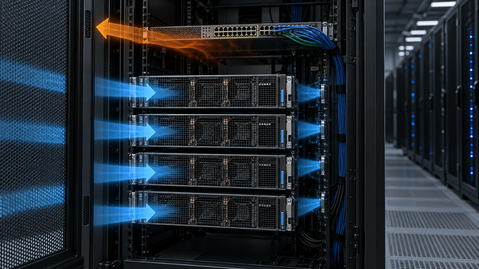
A GPU server fan wall is usually a bank of compact, high-speed axial modules working in parallel. In normal operation the bank develops a pressure difference across the chassis: air enters at the bezel, crosses filters where they are fitted, the accelerator heat sinks, DIMMs, network cards and power electronics, and leaves at the rear. Every module contributes to that pressure, and every heat sink in the path depends on it. The tray is one hydraulic system, not a row of independent spares.
This is why a replacement module cannot be approved by frame size, voltage and a similar maximum CFM figure alone. The useful comparison is installed: airflow and pressure at the defined command, temperatures at named components, acoustic and power behaviour, and the response of the platform's own control loop. NVIDIA's DGX SuperPOD reference architecture makes the same point one level up, requiring GPU systems to be designed as rack, server and facility systems together rather than as separate purchases.
For a 2U accelerator server the practical consequence is that two fans with the same free-air rating can behave differently once they are fitted. Blade geometry, motor, bearing drag and the impeller's response to a restrictive bank all change the airflow actually delivered at the pressure the chassis presents. AMCA's material on installed system effects is explicit that catalogue curves are measured in idealised arrangements and that the installed operating point has to be found, not assumed from the data sheet.
MEGA Tech develops custom DC cooling-fan samples for normal equipment cooling. Given a reference fan from SANYO DENKI, Delta, SUNON, NMB or ebm-papst, we review the mechanical envelope, the electrical interface and the installed duty, then propose a sample for the customer's own validation on the real chassis.
A Stopped Module Is a Leak, Not a Wall
The N+1 argument is usually arithmetic. The failure mode is not.
The standard redundancy argument runs like this: fit one module more than the heat load needs, and if a module is lost the survivors still cover the duty. The arithmetic is correct and the conclusion is often wrong, because it treats a stopped rotor as a wall that removes exactly one module's share of the flow.
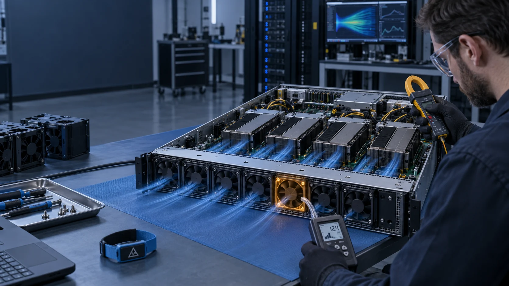
A stopped rotor is not a wall. It is a low-resistance opening in the same plane as its neighbours. Once the survivors raise the pressure across the bank, part of that pressure difference appears across the stopped position and air is driven through it backwards, from the downstream heated side into the upstream conditioned side. The leak does two things at once: it removes more flow than the failed module's share, and it feeds already-warmed air into the inlets of the modules immediately beside it.
The second effect is the one that catches teams out. The failed module itself is no longer dissipating, so any telemetry attached to it looks benign or simply disappears with the module. The component that crosses its limit is usually a neighbour, or a device sitting in the flow shadow downstream of the stopped position, which now receives less flow arriving at a higher inlet temperature.
This is why the one-module-out test is not a check that temperatures stayed the same. It is a check on which component moved first, by how much, and whether the platform's control loop responded in time. Vendors describe the same mechanism from different angles: NVIDIA's hybrid-cooling guidance treats the rack as one thermal system rather than a set of independent boxes, and switch vendors that publish fan-module rules warn that single-rotor and dual-rotor modules must not be mixed in one chassis, precisely because their different pressure and speed behaviour changes what the surviving modules end up doing.

Three States to Prove Before You Call a Tray Redundant
The acceptance plan needs a normal state, a degraded state and a service/replacement state.
The first measurement is the installed working point. A differential-pressure measurement across the relevant chassis region, combined with a representative fan curve or an accepted flow-measurement method, is more useful than reading a maximum CFM figure off a data sheet. Record the fan command and the resulting RPM at the same time, because the command is what the platform will actually apply.
The second measurement is a thermal map, not one exhaust sensor. Use permitted platform telemetry together with external instrumentation to compare inlet air, outlet air and the components that set the design limit: accelerators or their cold plates, memory, network cards, storage and power supplies. A single rear-exhaust reading can look healthy while a local inlet has already crossed its limit.
The third measurement is the control response. Confirm pinout and signal semantics before connecting a candidate module: supply range, PWM frequency and logic, tach pulses per revolution, the rotor-lock or alarm output, inrush current and the platform's expected fault-clear behaviour. Then check the timing, because a fan that eventually reaches full speed may not do so inside the window the platform's thermal model assumes.
| State | What changes | What to record |
|---|---|---|
| Normal loaded duty | All modules running at the design workload and design inlet temperature | Fan command and RPM, module current, tray pressure, and the temperatures of the components that set the limit |
| One module unavailable | One specified module is stopped or isolated; the platform's fault response is active | Fault-detection latency, surviving-module command, reverse flow at the stopped position, the component thermal map and any workload derate |
| Replacement / restart | A candidate module is fitted and the tray is restarted, or hot-swapped only where the platform permits it | Connector fit, startup and inrush current, PWM and tach behaviour, alarm clearing, and a repeat of the thermal result |
- Keep chassis configuration, inlet condition, voltage and speed command comparable between states
- Measure pressure and flow evidence as well as temperature
- Check named component telemetry, not only an exhaust sensor
- Treat control and restart behaviour as part of thermal qualification, not as a separate electrical check
- Record the failed module's own telemetry for context, but do not use it as the acceptance signal
Interactive: Why One Failed Fan Is Not a Simple Percentage Loss
Switch between states to see the evidence that should change with the fan tray.
This model is a visual checklist, not a CFD result and not an approval calculator. The arrows illustrate direction and the control response illustrates the test question: did the survivors recover the required duty without pushing a named component or a neighbouring inlet past its limit?
Use it to brief the test team rather than to replace the test. The three states in the model map directly onto the three measurements in the previous section, so the same run of the equipment can produce the working point, the thermal map and the control-response evidence together.
What to Record in the Degraded State
The one-module-out run is the expensive part of the programme. Capture enough evidence that it does not have to be repeated.
Two rows in that table are routinely skipped. Reverse flow at the stopped position is usually inferred rather than measured, which turns the largest uncertainty in the whole exercise into an assumption. Control latency is usually recorded as a success or a failure rather than a number, which means a marginal response cannot be distinguished from a comfortable one.
Recording the tray pressure and the surviving-module duty together also gives the equipment team something a replacement review needs later: a baseline. When a candidate module is proposed, the question is not whether it matches the original data sheet, but whether it reproduces this baseline at the same command on the same chassis.
| Signal | Source | What a pass looks like |
|---|---|---|
| Tray differential pressure | Differential-pressure transmitter across the tray region | Holds the value that supports the required component temperatures at the design workload |
| Surviving-module duty | Platform telemetry (BMC or equivalent) | Reaches the commanded speed without exceeding the module's own electrical or thermal limits |
| Reverse flow at the stopped position | Anemometer, vane or tuft check at the stopped module, tray running | Quantifies the leak so the flow loss is measured rather than assumed |
| Component thermal map | Permitted platform telemetry plus external instrumentation | Named hot spots stay inside the server maker's limits at the design workload and inlet condition |
| Alarm and control latency | Platform event log with timestamps | The fault is detected and the survivors ramp inside the platform's stated response window |
| Acoustics and input power | Sound level meter and DC power meter | The recovered speed stays inside the site's acoustic budget and the rack's power allocation |
Read the Published Airflow Budget Before You Pick a Module
Accelerator servers publish the airflow they need. It is worth reading those numbers before any replacement is proposed.
NVIDIA publishes both the environmental envelope and the airflow for its GPU systems, which makes the arithmetic on a fan tray concrete. The DGX H100/H200 user guide states an operating temperature range of 5 C to 30 C and a front-to-back airflow of 1,105 CFM at 80% fan pulse-width modulation, with a heat output around 38,500 BTU per hour. A fully populated DGX SuperPOD node is rated at roughly 10.2 kW.
Those figures matter to a tray review because they set the order of magnitude of what a module has to carry. A 2U accelerator chassis with eight modules does not give each module an eighth of the total in practice, because the bank is not perfectly uniform and some positions work against a more restrictive path than others. The nominal share is a starting point for the review, not the design duty.
They also explain why a 'close enough' replacement is not good enough. When a tray is already being asked to deliver a published airflow at a defined fan command, the margin between acceptable and marginal inlet temperature is small, and a module whose curve is slightly softer at the installed pressure consumes that margin without any obvious symptom.
| Tray state | Modules turning | Nominal share of design flow | Reality check |
|---|---|---|---|
| All modules healthy | 8 | 100% | Baseline. Record the installed working point at the design workload and inlet temperature. |
| One stopped, position sealed | 7 | About 87.5% by arithmetic | Only valid if the stopped position cannot pass air. Most trays do not seal themselves. |
| One stopped, position open | 7 | Less than 87.5%; measure it | The stopped position leaks backwards, so the survivors do not simply split the remainder. |
| One stopped, survivors at full command | 7 | Depends on the tray's speed margin | Prove it at the design inlet temperature, not at bench conditions with a cold chassis. |
Hybrid and Liquid Cooling Change the Air-side Duty, They Do Not Remove It
Cold plates move most of the accelerator heat, but the tray still has work to do.
Direct liquid cooling removes the largest single heat source from the air path by attaching cold plates to the accelerator dies, high-bandwidth memory and switch ASICs. That is a large change and it is why high-density GPU racks are increasingly liquid-cooled. It is not the same as removing the air side.
What remains on air typically includes memory modules outside the cold-plate envelope, network interface cards, storage devices, voltage regulators and the power supplies. NVIDIA's guidance for its own hybrid systems makes the split explicit, describing designs in which the majority of the heat is dissipated by liquid while the remainder is handled by air, and noting that airflow has to stay aligned across the components that still depend on it so that the air-cooled parts are not starved.
The fans that serve that residual air side are also part of a redundant set, and their failure modes are unchanged. If anything the duty is less forgiving, because a liquid-cooled system often runs denser and at a higher rack power than the air-cooled design it replaced, leaving less air-side margin per remaining component.
Mechanical discipline matters more here, not less. Cooling guidance in this class of equipment repeatedly requires blank modules or filler panels in unused slots, because an open slot is simply another leakage path that lets air bypass the components it was meant to cool. A tray validation that ignores blanking will measure a flow distribution the equipment will never see in service.
A Practical Sample Plan for a Custom or Replacement Module
Send enough context to make the first sample useful instead of merely dimensionally correct.
Start with the reference label or data sheet, plus tray dimensions, mounting, airflow direction, a connector photo and pinout, nominal and permitted supply range, the fan command and feedback requirements, maximum available fan power, and the environmental conditions at the equipment. A photograph of the installed tray with the airflow arrow visible saves a round of questions.
For a compact server module the sample path is normally: mechanical and interface review; curve and motor candidate selection; a small sample build; installed validation by the equipment team on the real chassis; then controlled production once the validation result is accepted. The installed validation is the step that decides the outcome, which is why the baseline numbers from the degraded-state run are worth having before the sample is specified.
A first-pass heat estimate can help decide whether the request is in the right order of magnitude. For heat that remains on the air side, CFM is approximately watts divided by 1.76 times the permitted air temperature rise, at near-sea-level density. A 600 W air-side load with a 12 C permitted rise works out at roughly 28 CFM before the pressure path is considered. That number is a sanity check on the requirement, not a selection result, because the fan has to deliver it at the pressure the chassis actually presents.
Validation Mistakes That Pass on Paper
These are the shortcuts that produce a signed report and an unexplained thermal alarm later.
Every item on that list shares one property: it removes a measurement and replaces it with an assumption. The assumption is usually reasonable. The difficulty is that a thermal limit is not crossed by an average, it is crossed by one component in one position, and the shortest path to finding that component is to measure rather than to reason.
A useful discipline is to write the acceptance test as a sequence of states with named instruments, rather than as a list of properties the tray should have. A test defined by states produces evidence; a test defined by properties produces an opinion.
- Counting modules to claim N+1 without ever running the one-module-out state
- Comparing free-air CFM instead of the installed working point at the chassis pressure
- Testing on a bench at room temperature rather than at the design inlet temperature
- Assuming the stopped position is sealed, so the reverse-flow leak is never measured
- Accepting connector compatibility without checking PWM, tach, alarm and inrush semantics
- Mixing single-rotor and dual-rotor modules in one chassis, which changes how the survivors behave
- Using a single exhaust temperature as the thermal map and missing a local inlet that has crossed its limit
- Forgetting that a liquid-cooled platform still has an air-cooled remainder with its own fan tray
Recommended Fan Starting Points
These catalogue series may be suitable starting points for this application. Final selection depends on the installed airflow, static pressure, voltage, noise target and operating environment.
Request a sample for validation on your equipment.
Engineer FAQ: GPU Server Fan-Tray Validation
Questions worth resolving before a fan-tray replacement or custom sample is released.
Q: Does an N+1 fan tray automatically keep the server inside its temperature limits after one module fails? A: No. Prove the one-module-out state at the relevant workload and inlet condition. The stopped module is a leakage path, so the bank loses more than that module's share of flow, and the component that moves first is often a neighbour or a device in the flow shadow downstream.
Q: Can a matching frame, voltage and RPM be called a drop-in replacement? A: No. Confirm the installed airflow and pressure duty, connector and signal behaviour, startup current, airflow direction, mechanical access and the component thermal map. Frame size and voltage are necessary conditions, not sufficient ones.
Q: Does liquid cooling remove the need to validate server fans? A: No. Cold plates cool only the parts connected to their loop. Memory outside the plate envelope, network cards, storage, voltage regulators and power supplies typically remain on the air side, and that air side still has a redundant fan set with the same failure modes.
Q: How long should the one-module-out test run? A: Long enough for the thermal mass of the heat sinks and the chassis to settle and for the platform's control loop to finish responding. A short run shows the transient, not the steady state the acceptance limit refers to.
Q: Can a failed module be left in place until the next maintenance window? A: Only against the platform's own guidance and the recorded degraded-state result. A stopped module that is still fitted may behave differently from a module that has been removed, because the empty position is a larger opening than the stalled rotor.
Q: What should an equipment team provide for an initial MEGA Tech review? A: The reference fan label or data sheet, tray drawing or photos, frame and thickness, voltage, connector and pinout, PWM/tach/alarm requirements, airflow direction, the permitted temperature range, and the baseline numbers from the normal and one-module-out states if they already exist.