A grow light is a thermal product before it is a lighting product
A horticultural fixture runs a 16 to 20 hour photoperiod every day of the year, so its fans accumulate more running hours in twelve months than a server fan does in two years.
Growers buy a fixture on µmol/J, and that is the right purchase metric. The engineering problem starts when it is mounted: the same photon output has to be produced for six thousand hours a year or more, in a room at 24 to 28 degrees Celsius and 70 to 85 percent relative humidity, often above a canopy that blocks the air the fixture has just heated.
The failure that ends a fixture's useful life is rarely a dead LED. It is flux maintenance. Output falls as junction temperature rises and as the phosphor and the silicone encapsulant age, and the driver's electrolytic capacitors age on their own schedule. A fixture that loses fifteen percent of its photon output in year two has to be replaced early, and the number that decides that is the board temperature, not the room temperature.
This article covers the air side of that problem: where the heat goes, why uniformity along a one-and-a-half metre bar matters more than total airflow, how to size and select the fan, what the growing environment does to the variant, and what to put in a specification so the fixture can be validated.
- Treat the fixture as a thermal system that emits light, not as a lamp that gets warm
- Set the acceptance number on the LED board, because that sets flux maintenance
- Design the air path along the whole bar, not just at the fan
- Choose the variant from the room humidity and cleaning regime
Where the electrical power actually goes
Only part of the input power leaves the fixture as photons. The rest is heat that air has to move.
A horticultural LED is quoted by efficacy in micromoles per joule. For a modern top light that figure sits around 2.7 to 3.5 µmol/J, and it is the ratio of photon flux delivered to electrical power drawn. Photons carry real energy away: at 660 nanometres one micromole carries about 0.175 joules, so an efficacy of 3.0 µmol/J puts roughly 52 percent of the input power out as light.
The remainder is dissipated inside the fixture. That heat is generated in the junction, conducted through the solder joint and the metal-core board, spread into the extrusion, and handed to the air. Every step adds thermal resistance and every one adds to the junction temperature rise above the room.
For sizing, the useful number is the heat that reaches the air. Take a 640 watt bar at 3.0 µmol/J: about 55 percent of the input leaves as photons and about 45 percent, roughly 290 watts, has to be removed by the heatsink. That is roughly twice what a general lighting fixture of the same wattage rejects, because a lower-efficacy white source puts a larger share of its input into heat.
Two consequences follow: a horticultural fixture is not an indoor luminaire with a longer life, and the airflow calculation starts from electrical power rather than from watts per metre of extrusion.
| Quantity | Unit | Value for a 1.5 m bar | What it decides |
|---|---|---|---|
| Electrical input power | W | 640 | The starting number, from the driver datasheet at the actual mains voltage |
| Efficacy | µmol/J | 3.0 | How much of the input leaves as photons |
| Photon energy at 660 nm | J per µmol | 0.175 | Converts efficacy into a radiant fraction |
| Radiant fraction | percent of input | about 55 | The share that does not have to be cooled |
| Heat into the fixture | W | about 290 | The load the heatsink and fan must remove |
| Heat per metre of bar | W per m | about 193 | Sets the fin area and the airflow per segment |
What the heat does to the LEDs and to the driver
The number that matters is the junction temperature. The number usually reported is the room temperature, which is not the same thing.
Horticultural LED packages in bar lights are commonly rated to a maximum junction temperature of 85 degrees Celsius. That rating is not a target; it is the point beyond which the manufacturer stops supporting the flux maintenance claim and where the phosphor and the encapsulant degrade noticeably faster.
Flux maintenance is published as a family of curves, produced under the LM-80 test method and extrapolated under TM-21. The curve is indexed by case temperature, and the standard industry claim is written for a specific case temperature, most often 55 degrees. A fixture whose board runs at 75 degrees is not on that curve; it is on a worse one, and the difference in reported maintenance hours is large.
The driver has its own limit. Electrolytic capacitors follow an Arrhenius relationship in which every additional ten degrees of core temperature roughly halves remaining life. A capacitor rated for five thousand hours at 105 degrees may be rated for twenty thousand at 85. Put the driver in the same still, humid air as the LEDs and the fixture's life is set by a component the grower never thinks about.
So a fixture should be specified and accepted on board temperature and driver temperature, measured at the mounting points the manufacturer nominates, at the worst room condition the site will see. Room temperature is an input to that calculation, not the result.
| Component | Limit | Measured where | What happens past it |
|---|---|---|---|
| LED junction | typically 85 °C maximum | Calculated from board temperature and package thermal resistance | Maintenance claim no longer applies |
| LED board or case | the temperature the maintenance curve is indexed to, often 55 °C | Thermocouple on the board at the manufacturer's point | Published hours no longer describe the fixture |
| Driver capacitor | typically 105 °C rated; life set by the core temperature reached | Driver case, hottest point, fixture at full output | Life halves for every extra 10 K |
Why airflow uniformity along the bar matters more than total airflow
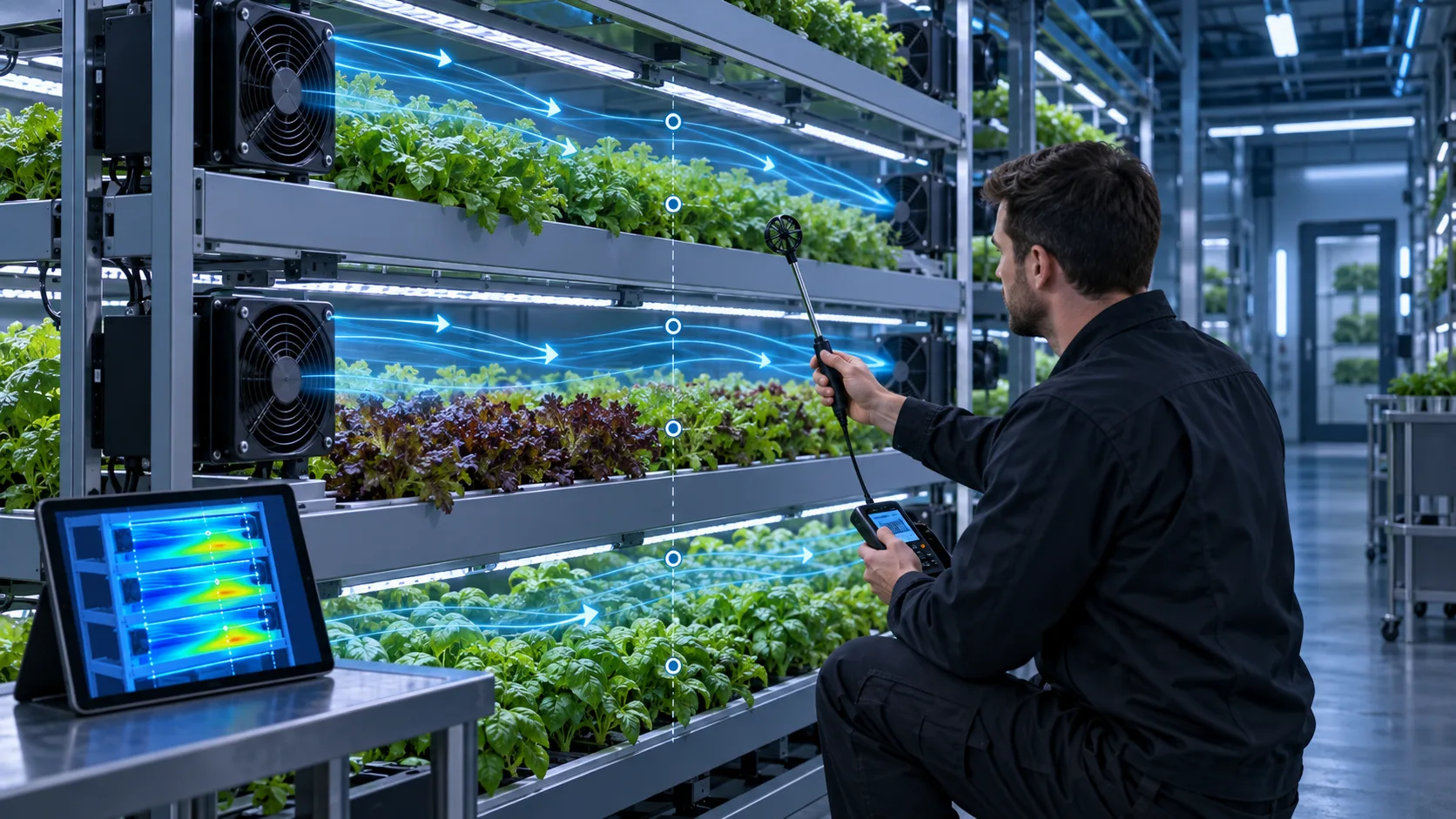
A grow light bar is a long, narrow heat source with a fin stack running its whole length, and a fan mounted at one end does not deliver its airflow to the far end.
The instinct is to size on total airflow: compute the heat load, choose a temperature rise, divide, and pick a fan whose free-air rating covers the result. On a compact enclosure that is defensible. On a one-and-a-half metre extrusion it is not, because the airflow a fan produces at its own outlet is not the airflow that reaches the far end of the fin stack. Air escapes sideways between the fins, the boundary layer thickens along the channel, and available static pressure falls with distance from the fan.
With a single end-mounted fan the measured gradient is steep. Face velocity at the fan end can be around 1.4 metres per second while the last quarter of the bar sees 0.2 metres per second or less. Because heat input per metre is roughly constant, the local temperature rise follows the inverse of the local airflow, and the board at the far end can be fifteen degrees hotter than at the fan end.
That gradient is the real failure mode. Flux maintenance is set by the hottest section, not the average, so a bar that is comfortable over its first metre and over its limit in the last third will lose flux at the rate of the last third, and growers will see a colour and intensity difference along its length.
The response is to change the distribution, not to raise the speed. Two or more fans along the bar, or one at each end so the two airflow fronts meet in the middle, flatten the velocity profile. Splitting the fin stack into shorter channels with a fan per channel does the same. In both cases the required total airflow falls, because the air is delivered where the heat is instead of being asked to travel.

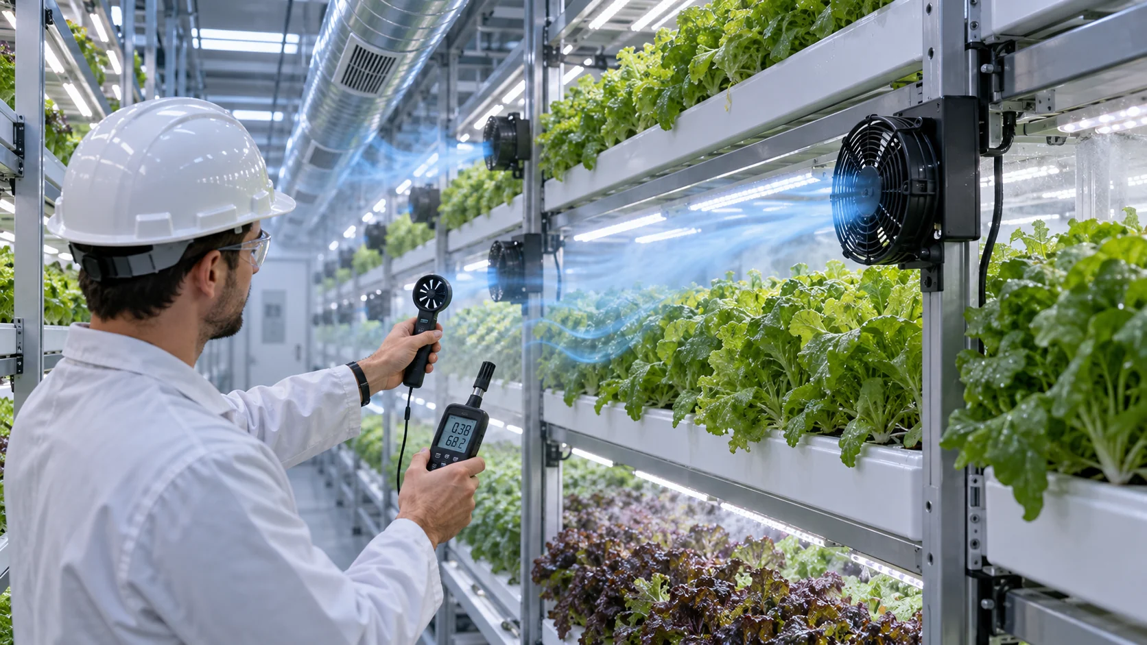
- Measure face velocity at the fin inlet, not at the fan outlet
- Sample at least four points along the bar: fan end, quarter, half, far end
- Accept on the worst point, not on the average
- Prefer distribution over speed: two moderate fans beat one fan at maximum
Sizing the airflow: a worked example
The airflow calculation is short, and doing it in public makes the assumptions visible.
Start from the heat that has to reach the air: about 290 watts for the 640 watt bar. Choose the air temperature rise between the inlet and the outlet of the fin stack. That is a design decision, not a constant: a small rise means more airflow, a larger rise means less airflow but a hotter extrusion. For a fixture-mounted fan in a plant factory, 12 kelvin is a workable compromise, because air entering the fins is already several degrees above the room.
Volumetric flow follows from the heat load, air density, specific heat capacity and the temperature rise. With air at 1.2 kilograms per cubic metre and 1005 joules per kilogram kelvin, the calculation gives about 72 cubic metres per hour, roughly 42 cubic feet per minute, for the whole 1.5 metre bar.
That is the airflow the fin stack must see, not the fan's free-air rating. The next section deals with the difference, and it is usually where a fixture ends up short.
The calculation scales linearly with length, which is useful. A 600 millimetre bar carries roughly 115 watts of heat and needs about 29 cubic metres per hour at the same rise; a 2.4 metre bar carries about 460 watts and needs about 115 cubic metres per hour. What does not scale linearly is a single fan's ability to deliver that airflow to the far end, which is why long bars need more fans rather than bigger ones.
| Bar length | Input power | Heat to air | Volumetric flow | CFM |
|---|---|---|---|---|
| 600 mm | 256 W | about 115 W | about 29 m³/h | about 17 |
| 1,000 mm | 427 W | about 192 W | about 48 m³/h | about 28 |
| 1,500 mm | 640 W | about 290 W | about 72 m³/h | about 42 |
| 2,400 mm | 1,024 W | about 460 W | about 115 m³/h | about 68 |
Static pressure comes before airflow: the fin stack is the system curve
A dense extrusion is a resistance, and the fan has to be selected where its pressure curve crosses that resistance, not where its free-air rating sits.
The fin stack is a set of narrow parallel channels. Air moving through them loses pressure to wall friction and to entrance and exit losses. Pressure drop rises roughly with the square of velocity, so a stack sized for 0.5 metres per second at 15 pascals needs about 60 pascals at 1.0 metres per second, not 30. That is the system curve, and it is why doubling fan speed does not double airflow.
The fan has its own curve, sloping from free-air delivery at zero pressure to zero delivery at shut-off. The operating point is where the two cross. A fan rated 120 cubic metres per hour free air may deliver about 85 at 15 pascals, and less if the fins are dusty. Selecting on the free-air number overstates installed airflow by roughly thirty percent here, which is often the whole margin.
Two further effects belong in the same calculation. System effect: a fan mounted close to a wall, a rail or a neighbouring fin block loses a measurable part of its rating, and the inlet clearance it needs usually exceeds the mechanical envelope. Contamination: in a growing room the air carries spores, mineral dust and sometimes fine water droplets, and every deposit raises the resistance of the channel and grille, moving the operating point down the curve over the fixture's life.
For a long bar, choose between one larger fan and several smaller ones on the system curve rather than on the airflow total. Distributed fans each work against a shorter channel, which is a lower resistance, and each serves a shorter length of extrusion. That is why a distributed arrangement reaches the same board temperature with less total airflow and degrades more gracefully when one fan slows.
| Check | Target or criterion | Why |
|---|---|---|
| Operating point | Delivered airflow at the fin stack pressure drop meets the worked requirement | Free-air rating is not installed airflow |
| Fin stack pressure drop | Measured or computed at design face velocity, dust condition stated | Resistance rises with velocity and contamination |
| Inlet clearance | One fan diameter unobstructed, or the system effect quantified | A fan against a rail loses rated pressure |
| Distribution | Face velocity inside the agreed band at every sample point | The hottest section sets maintenance |
| Redundancy | Board temperature inside its limit with one fan stopped | A stopped fan becomes a reverse-flow opening |
| Feedback | Tachometer or rotation detection wired to the controller | A stopped fan must be told apart from a slow one |
The growing environment decides the fan variant
Humidity, condensation and cleaning decide more about which fan survives than room temperature does.
A plant factory runs at 70 to 85 percent relative humidity and a greenhouse can go higher. When the lights go out the fixture cools within minutes, and any surface below the local dew point collects water. On a fixture with a 20 hour photoperiod that happens once a day, every day, for years. Water on a fan's board, bearing shield or connector begins a failure, and that failure is usually corrosion or a short rather than a mechanical seizure.
The IP rating is the first lever, and it is a trade-off rather than a free upgrade. An IP54 or IP55 fan keeps out dust and splash but still breathes room air through its motor, so moisture reaches the windings. A sealed IP65 or IP68 fan uses an encapsulated stator, which removes the moisture path but also removes the airflow path through the motor and reduces efficiency at a given size; it costs more and runs hotter internally, which has its own effect on bearing life.
Corrosion matters where the room is fed with acid or fertiliser dosing, where irrigation water is high in dissolved solids, or where the site is coastal. Salt mist and acidic aerosol attack the joints a fan is full of: aluminium blade to steel shaft, fastener to plated boss, and the exposed traces on the control board. A coating that survives an indoor dust test will often chalk and lift under cyclic salt and humidity.
Cleaning is the third constraint and the one most often missed. Many growers wash or wipe fixtures between crops, sometimes with a spray. A fan whose rating assumes clean water will not survive a spray containing a sanitiser. The mounting orientation should keep the inlet out of the spray path, and the rating should be chosen for the cleaning method actually used.
| Room condition | Fan implication | What to specify |
|---|---|---|
| Plant factory, 70-80 %RH, no spray | Condensation at lights-off is the main risk | IP55 with a conformally coated board and humidity-tolerant lubricant |
| Greenhouse with overhead irrigation | Direct water contact is possible | IP65 sealed motor and a shielded inlet position |
| Fertigation or acid dosing | Acidic aerosol and dissolved solids | Corrosion-resistant hardware plus a cyclic salt and humidity test |
| Coastal site | Salt mist on a continuously running fan | Salt-mist test condition in the qualification plan |
| Between-crop washdown with sanitiser | Chemical contact, not just water | Rating chosen for the cleaning agent, inlet out of the spray path |
Noise, duty cycle and control
A fixture fan runs almost continuously, and it is heard in a working space rather than in a machine room.
A plant factory is a workplace. People work between the racks, and a rack of bar lights with a fan at each end can hold dozens of small fans running at once. Small axial fans at high speed are the worst case: their blade-pass frequency sits where the ear is most sensitive, and many of them sum into a broadband hiss that is hard to attenuate.
The useful targets are a sound pressure level at the working position rather than a free-air sound power rating, and a limit on tonal content rather than on the overall level. A narrow tone at blade-pass frequency is more noticeable and harder to mask than a broadband level several decibels higher. For a fixture fan in a working space, around 40 decibels A-weighted at one metre with no tone more than about 8 decibels above the surrounding bands is a reasonable starting point.
Control is straightforward but has to be specified precisely. A four-wire fan takes a pulse-width modulated control signal, typically 21 to 28 kilohertz with 25 kilohertz nominal, and returns a tachometer signal at two pulses per revolution. The control input should be specified as open-circuit-means-full-speed, so a broken control wire fails towards cooling rather than towards heat.
The duty cycle is where a fixture differs from a cabinet: sixteen to twenty hours on, four to eight off, every day, which means thousands of start-stop cycles a year on top of the running hours. Each start draws several times the running current and each stop lets the bearing and lubricant settle. Start-up current has to be inside the controller's capability when several fans start together, and the bearing has to be qualified for the number of starts, not only the hours.
Life, maintenance and the signals that predict failure
Fan life has to be quoted at the temperature the fan actually sees, which is the air between the fins, not the room.
Bearing life is quoted as L10: the hours at which ten percent of a population is expected to have failed. That figure is indexed to a bearing temperature, which follows the air passing over the motor. A fan quoted at seventy thousand hours at forty degrees loses much of that life at seventy, because grease and bearing steel both age faster. When a vendor quotes a life figure, ask which ambient it was quoted at and whether that matches the air inside the fixture.
Grease life and bearing fatigue life are different limits and the shorter governs. In continuous hot duty the grease usually goes first, through base-oil loss and oxidation. The qualification should include a high-temperature running test at the fixture's real internal ambient rather than a room-temperature endurance run.
Maintenance in a growing room is mostly cleaning. Dust, spores and mineral deposits build on blades, grille and fins. The deposit adds mass and imbalance, which increases vibration and noise, and raises the resistance of the air path, which moves the operating point down the curve. A cleaning interval should be set from a measured airflow or board temperature, not from a calendar.
The predictive signals are already available on a four-wire fan. A tachometer reading that drifts downward at constant control duty indicates a bearing or deposit problem; a current reading that rises at constant speed indicates the same; a board temperature that rises at constant speed indicates a blocked fin stack. None needs an extra sensor, but the controller has to log them and the maintenance plan has to watch the trend.
| Item | What to specify | Why |
|---|---|---|
| L10 life | Hours at a stated ambient equal to the air inside the fixture | A room-temperature figure does not describe a fixture fan |
| Grease life | Stated separately, with the temperature basis | In continuous hot duty the grease fails first |
| Start-stop qualification | Cycles tested, with inrush current recorded | The photoperiod creates thousands of cycles a year |
| Cleaning trigger | A measured airflow loss or board temperature rise | Dust accumulation is site-specific |
| Predictive signal | Tachometer and current trend at constant duty | Both are already available on a four-wire fan |
How MEGA Tech supports a grow light fan program
MEGA Tech builds custom DC and EC cooling fans and selects them by operating condition rather than by part number.
For a horticultural fixture the work usually starts from a thermal target rather than a fan model. The fixture geometry, heat load per metre, room condition and the board temperature the grower needs are enough to define the airflow requirement and the pressure the fan must work against. From there the fan is chosen on its delivered operating point, and the arrangement along the bar can be tested before tooling is committed.
Samples are validated on the customer's own fixture: the fan runs in the real extrusion, with the real driver, at the real photoperiod and room humidity, and the board temperature and velocity profile along the bar are measured. A fan that passes on a bench and fails in the fixture was selected on the wrong number.
The boundary is worth stating. MEGA Tech supplies the fan, its control interface and its mechanical interface. We do not supply the driver, light engine, heatsink extrusion, fixture sealing, irrigation or climate controls, or the electrical safety design of the fixture. Those remain with the fixture designer, and the fan specification has to fit them.
- What we do: custom DC and EC axial and centrifugal fans, selected by operating condition, samples validated on the customer's fixture
- What we need: airflow and static pressure at that airflow, temperature and altitude basis, voltage tolerance, control interface, connector, envelope, noise target, life assumption
- What we do not supply: driver, light engine, heatsink, fixture sealing, irrigation or climate control, fixture electrical safety design
- How to start: send the fixture geometry, heat load per metre, room condition and board temperature target
Engineer FAQ: LED Grow Light Fixture Cooling
The questions that come up most often when a fixture thermal problem is handed to a fan supplier.
Q: How much airflow does a grow light bar need? A: Start from electrical input power, take off the fraction that leaves as photons, and divide the remainder by air density, specific heat capacity and the temperature rise you accept. A 640 watt, 1.5 metre bar at 3.0 micromoles per joule gives roughly 290 watts of heat and roughly 72 cubic metres per hour at a 12 kelvin rise.
Q: Why does the far end of my bar run hotter? A: The fan delivers its pressure at its own outlet and the fin channel consumes it along the length. Face velocity falls with distance and local temperature rise follows. Two fans along the bar, or one at each end, flatten the profile and usually need less total airflow than one larger fan.
Q: Can I use an IP68 fan to solve humidity? A: It removes the moisture path through the motor, but a sealed motor also loses its internal airflow path and runs hotter, shortening bearing and grease life. Choose the rating from the cleaning method and condensation risk, then check the thermal penalty.
Q: Do I need a tachometer signal? A: Yes, so the controller can tell a stopped fan from a slow one and maintenance can trend speed at constant duty. Without it, a stopped fan in a multi-fan bar stays invisible until the board temperature shows up in the crop.
Q: Should the fan run at full speed all the time? A: Usually not, provided the board temperature stays inside its limit at the worst room condition. Reduced duty cuts noise and extends life. Specify the control input so a lost signal commands full speed.
- Size on heat load, not on fixture wattage
- Check the operating point, not the free-air rating
- Accept on the hottest point along the bar
- Choose the variant from the cleaning and condensation regime
- Log the tachometer so a slow fan is visible before it stops
Questions for a design review
A short list that turns the discussion from fan models back to the numbers the fixture has to meet.
- What is the heat load per metre, from driver input power and measured efficacy?
- What board temperature is the flux maintenance claim indexed to, and what is measured at the worst room condition?
- What air temperature rise was used to size the airflow, and who agreed to it?
- What is the fin stack pressure drop at design face velocity, and the delivered airflow at that pressure?
- What is the face velocity at four points along the bar, and the spread between highest and lowest?
- What happens to board temperature when one fan stops: isolated, or a reverse-flow path?
- What is the fan's L10 life at the air temperature inside the fixture?
- What IP rating does the cleaning method require, and what thermal penalty does it impose?
- How many start-stop cycles per year does the photoperiod create, and is the bearing qualified?
- Which signal tells maintenance that airflow is being lost before the crop does?