A Vertical Farm Can Have Enough Airflow and Still Have Uneven Crops
Total CFM does not prove that every cultivation layer receives the same useful air, temperature, humidity or carbon dioxide condition.
Multi-level racks create a three-dimensional resistance network. Leaves and trays obstruct the path, lights add heat, irrigation adds moisture, and the upper and lower layers experience different buoyancy and return-air conditions. A large air-conditioning discharge may satisfy the room average while the centre of a rack remains humid and stagnant or the top layer receives excessive velocity.
The engineering solution is to separate two jobs. Global air delivery removes the facility heat and moisture load, establishes the supply and return pattern, and controls the room condition. Local rack or aisle fans mix air through the crop zone and reduce layer-to-layer variation. The two systems should be designed together but measured with different metrics.
This guide focuses on fan selection and validation. It does not prescribe a crop-specific climate recipe. Crop, growth stage, lighting, irrigation, HVAC capacity and disease-management requirements remain with the farm's agronomy and environmental-control teams.
Why Uniformity Matters More Than a Single Average
The crop experiences a local microclimate, so the average room temperature or RH can conceal the layer that is actually limiting growth.
Recent vertical-farm research evaluates uniformity at both facility and crop-bed scales. A validated CFD study of container and building farms found that direct discharge, rack fans and aisle fans affect different parts of the air-distribution problem. Field measurements in multi-layer cultivation also show meaningful variation in fan outlet velocity, air speed, temperature and RH across the growing area.
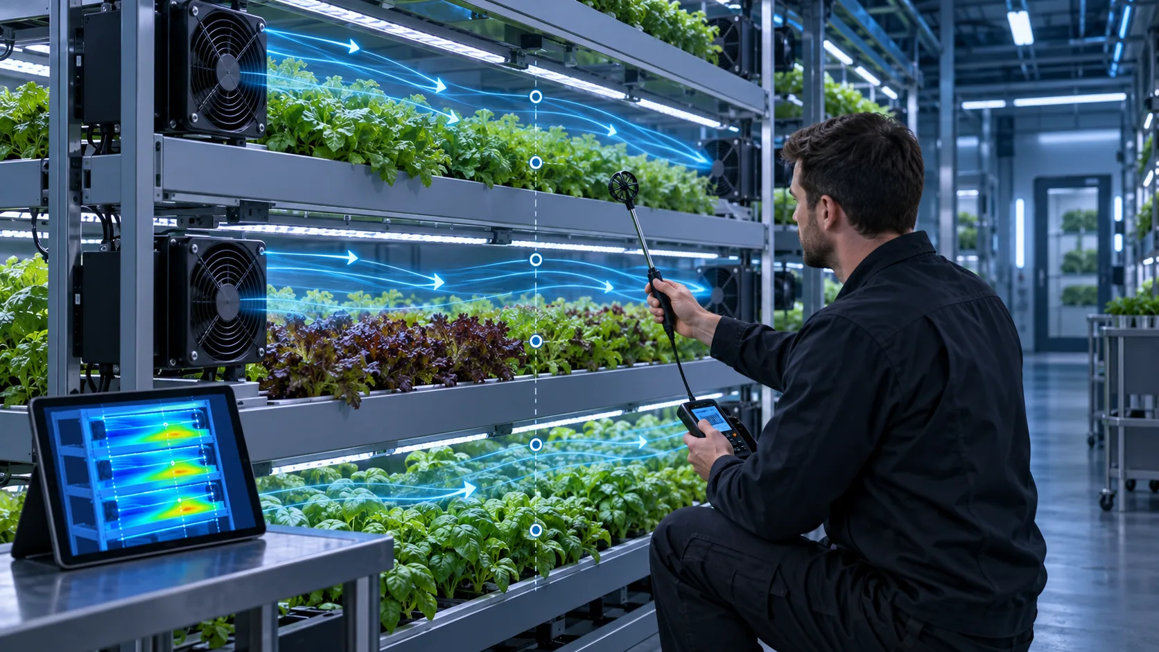
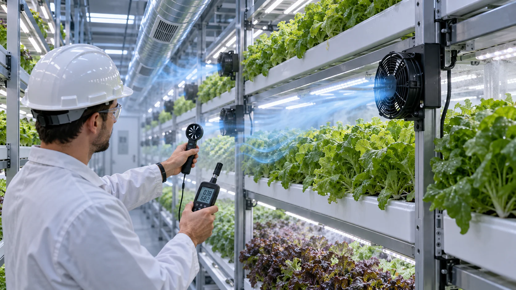
For engineering purposes, map the canopy or leaf-zone condition rather than only measuring at the HVAC supply. Use a repeatable grid: near the supply, centre of the rack, far end, upper layer, middle layer, lower layer and return side. Repeat with lights on, irrigation active, doors closed and the intended crop density.
A simple planning statistic is the coefficient of variation, CV = standard deviation divided by the mean. For an illustrative set of canopy velocities with a mean of 0.20 m/s and a standard deviation of 0.04 m/s, CV is 20%. That number is not a universal agronomic limit; it is a transparent way to compare two layouts using the same measurement method.
| Measurement | Why it matters | Where to record |
|---|---|---|
| Canopy air speed | Shows local mixing and stagnant pockets | above and between each layer |
| Air temperature | Reveals light and equipment heat accumulation | near leaves, supply and return |
| Relative humidity | Shows moisture distribution, not only room average | same points as temperature |
| VPD or dew-point margin | Connects temperature and RH to condensation/transpiration risk | crop-zone sensor pairs |
| Fan command and current | Connects uniformity to energy use and fan duty | each fan branch or controller |
Choose the Fan From the Rack and Grille Resistance
A circulation fan that looks powerful in free air may lose useful reach when mounted behind a guard, filter, duct or narrow rack opening.
Define the local air path: fan inlet, protective grille, filter if used, rack opening, crop canopy, return path and any bend or diffuser. For a global supply system, include the duct, diffuser, dampers, coil and return path. The fan's P-Q curve must intersect the installed system curve at the required flow or velocity.
For a worked example, suppose a rack zone needs 900 m3/h of mixed air at a defined pressure. The grille and mounting add 25 Pa, the short duct adds 35 Pa and the rack/canopy path adds 40 Pa. The fan selection point is about 900 m3/h at 100 Pa before a design margin. If a filter later adds 35 Pa, the same fan command may deliver less useful mixing and increase the local variation.
Avoid using high pressure to create a narrow jet that dries one row and leaves another stagnant. A lower-speed fan with a better position, diffuser or baffle can produce better crop-zone uniformity and lower energy. The selection should include throw, mixing pattern, noise, electrical input, control range and maintenance access, not only maximum CFM.
Interactive: Watch Layer Mixing and Moisture Pockets Change
The animation separates a global supply path from local rack mixing and shows how a stagnant layer can remain when the room average looks normal.
Use the model to build a test matrix. Compare global supply only, global supply plus rack fans, and a revised fan/baffle layout. For each state, record canopy velocity, temperature, RH and dew-point or VPD margin at the same grid points. If the rack fan simply recirculates air inside one aisle, it may improve one layer while leaving the return path and moisture balance unchanged.
Do not interpret the animation as a crop recipe or CFD result. Its purpose is to make the engineering question visible: where does air enter, where does it spend pressure, where does moisture accumulate, and which fan command changes the actual crop-zone map?

Humidity, Dew Point and VPD Must Be Read Together
Relative humidity alone can mislead because the same RH represents different moisture conditions at different temperatures.
A warm upper layer and a cooler lower layer can show similar RH while having different dew-point margins. A cold coil, metal rack or supply surface can fall below the local dew point and create condensation even when the room RH display appears acceptable. Conversely, a high-temperature zone can have a lower RH but still require better air movement to control transpiration and leaf temperature.
For a transparent example, air at 24°C and 70% RH has a dew point around 18°C. If a metal surface or coil reaches 17°C, condensation risk exists at that location even though the room temperature is 24°C. The exact dew point should be calculated with the sensor accuracy and the selected psychrometric method; the example is for understanding the margin, not for defining a crop limit.
VPD is also temperature-dependent. Use paired temperature and RH measurements at the canopy rather than calculating VPD from a single room sensor. A local circulation fan can reduce a moisture pocket, but it cannot replace dehumidification when the total latent load exceeds the HVAC capacity.
Fan Placement Should Follow the Crop-Zone Failure Mode
The best fan position depends on whether the problem is upper-layer heat, central moisture accumulation, end-of-rack stagnation or a short-circuit path near the supply.
Upper layers can receive different air because warm air rises and the top of a rack may be closer to lights or the ceiling. Lower layers can experience restricted return flow or cooler surfaces. A fan mounted at the end of an aisle may push a strong jet past the nearest leaves while the far end remains under-mixed. A fan mounted directly at a crop can increase local velocity without improving the whole layer.
Use smoke, lightweight streamers or particle visualization only as a diagnostic aid. Confirm the result with anemometer measurements and the temperature/RH grid. If a baffle or diffuser is added, measure the pressure change and fan current; an apparently smoother flow can also reduce the available circulation if it consumes too much pressure.
A practical prototype often uses adjustable brackets or two fan positions. This lets the farm compare sidewall, aisle and rack-level mixing without committing to a production cutout before the failure mode is understood.
- Map the upper, middle and lower layers separately.
- Measure both the supply side and the return side of the rack.
- Check whether a local fan improves the far end or only the nearest leaves.
- Record fan current and pressure after adding guards, filters or baffles.
- Keep the airflow gentle and uniform enough for the crop and growth stage.
Humidity Is Also a Fan Reliability Problem
High RH, condensation, fertilizer aerosols and cleaning chemicals can shorten fan life even when the airflow layout is correct.
Specify the actual environment near the fan: continuous RH range, condensation events, nutrient mist, cleaning cycle, water spray, temperature, salt or fertilizer deposits and expected operating hours. The fan's frame, motor electronics, bearing, connector and cable exit may need different protection strategies. An IP label on one component does not certify the rack, duct or power connection.
Place the fan so it does not become a water or nutrient collection point. Provide drainage where required, avoid direct spray, protect the connector and leave access for cleaning. A fan that accumulates leaf debris or dust on its inlet can change its balance and pressure-flow behavior, increasing noise and reducing useful mixing.
For a sample validation, cycle the fan through the intended humidity and cleaning states, then re-check startup, current, vibration, acoustic output and airflow. The objective is not to invent a universal life number; it is to connect the selected construction and maintenance plan to the actual farm environment.
Energy Use: More Fan Speed Is Not the Same as Better Uniformity
A fan layout can improve crop-zone uniformity while using less energy if the air is directed to the layers that need it instead of over-driving the whole room.
Use PWM or EC control when the fan and controller support it, but validate the minimum stable duty and the response to humidity or temperature changes. A fixed high-speed command can increase noise, evaporation and fan power without solving the stagnant zone. A slow control loop can also hunt if the sensor is placed in a representative but delayed location.
As an illustrative comparison, four fans drawing 0.30 A from a 24 V rail use about 28.8 W. If a revised layout lets the controller operate them at 0.18 A for most of the day, the input becomes about 17.3 W, saving 11.5 W continuously. Across 16 hours, that is about 184 Wh per day for those fans. The real result depends on the fan current curve, HVAC interaction and crop response.
The energy report should include HVAC impact. A local fan may add electrical power but reduce moisture or temperature non-uniformity enough to prevent overcooling or excessive dehumidification. Measure the whole control state rather than claiming that the fan alone saved energy.
Acceptance: Define a Crop-Zone Map Before Production
The acceptance plan should show where the fan helps, what condition it protects and how the result changes with crop density and service state.
Create a fixed measurement grid at the canopy: at least near, middle and far positions for each rack tier, plus supply and return points. Record air speed, temperature, RH, dew point or VPD, light state, irrigation state, fan command, current and room HVAC state. Repeat after the plants reach the representative canopy density because leaves change the resistance and mixing pattern.
Compare the baseline and revised layouts using the same statistics: mean, minimum, maximum, standard deviation or CV, and the count of points outside the farm's agronomic band. A single maximum velocity or average RH number cannot describe a multi-layer system.
Include the failure and maintenance cases: one local fan stopped, filter loaded, supply changed, door opened and condensation event. The result should identify whether the system remains within its approved operating band or whether the farm needs an alarm, service action or controlled crop-zone derating.
| State | Measurements | Question |
|---|---|---|
| Global supply only | layer velocity, temperature, RH and HVAC state | where are the stagnant or warm zones? |
| Global plus rack fans | same grid plus fan command and current | does local mixing improve uniformity? |
| High canopy density | velocity, RH/VPD and leaf-zone condition | does the crop change the system curve? |
| Loaded or wet service state | pressure, current, condensation and noise | does maintenance reduce the margin? |
| One local fan failed | temperature/RH spread and alarm response | is the crop or equipment protected long enough? |
Where MEGA Tech Fits In
We help vertical-farm teams develop fan samples around the rack, crop zone, humidity and maintenance conditions instead of quoting a free-air number alone.
MEGA Tech can review custom axial fans, compact blowers and fan modules for rack circulation, aisle mixing, electronics cabinets, LED-light heat paths, filtration and dehumidification support. The review can cover airflow direction, pressure-flow behavior, PWM or voltage control, FG/RD feedback, connector and cable exit, bearing configuration, humidity and corrosion exposure, noise, vibration, filter condition and small-batch sampling.
For a first review, provide the rack layout, tier spacing, crop or canopy condition, supply and return locations, heat and moisture loads, target velocity or uniformity metric, temperature/RH/VPD range, filter or grille, fan envelope, voltage, control interface, cleaning process and expected quantity. A map showing the current hot or humid zone is more useful than a total room CFM number by itself.
We can also evaluate cost-competitive replacements for Sanyo Denki, SUNON, Delta, NMB or ebm-papst fans when the replacement is compared at the same installed pressure, humidity state, electrical interface and crop-zone measurement points.
Engineer FAQ: Vertical-Farm Fan Selection
These questions connect fan selection to crop-zone uniformity, moisture control and maintenance evidence.
Q: How much airflow does a vertical farm need? A: There is no universal CFM. Define the crop-zone velocity, heat and moisture load, rack resistance, supply/return layout and the uniformity metric.
Q: Does a larger circulation fan guarantee more uniform crops? A: No. A strong jet can short-circuit, bypass layers or over-dry one zone while leaving another stagnant.
Q: Can room RH prove that the crop zone is safe? A: No. Measure temperature and RH at the canopy and calculate dew-point or VPD margin at the same locations.
Q: Should rack fans replace HVAC or dehumidification? A: Usually not. Rack fans mix and redistribute air; they do not remove the total heat or latent moisture load.
Q: What fan protection matters in a vertical farm? A: Define RH, condensation, nutrient mist, cleaning spray, dust, connector and drainage conditions for the actual installation.
Q: Can MEGA Tech support small first builds? A: Yes. We can start from a rack sample or layout, adjust fan and mounting parameters, build samples and support velocity, humidity and thermal validation before production.
Vertical-Farm Fan Review Checklist
Use this checklist before freezing fan position, frame, control curve or maintenance requirements.
- Are global supply and local rack mixing treated as separate functions?
- Where are the upper, middle and lower crop-zone measurement points?
- What velocity, temperature, RH, dew point or VPD metric defines acceptance?
- Does the fan deliver the required flow at the grille, rack and canopy pressure?
- Was the map repeated at representative crop density and lighting load?
- Were condensation, nutrient mist, cleaning spray and connector exposure considered?
- Does PWM control reduce energy without creating humidity or velocity oscillation?
- What happens if one rack fan stops or a filter loads?
- Were noise, vibration and maintenance access checked at the installed mount?
- Which values are measured, estimated or owned by the agronomy and HVAC teams?