
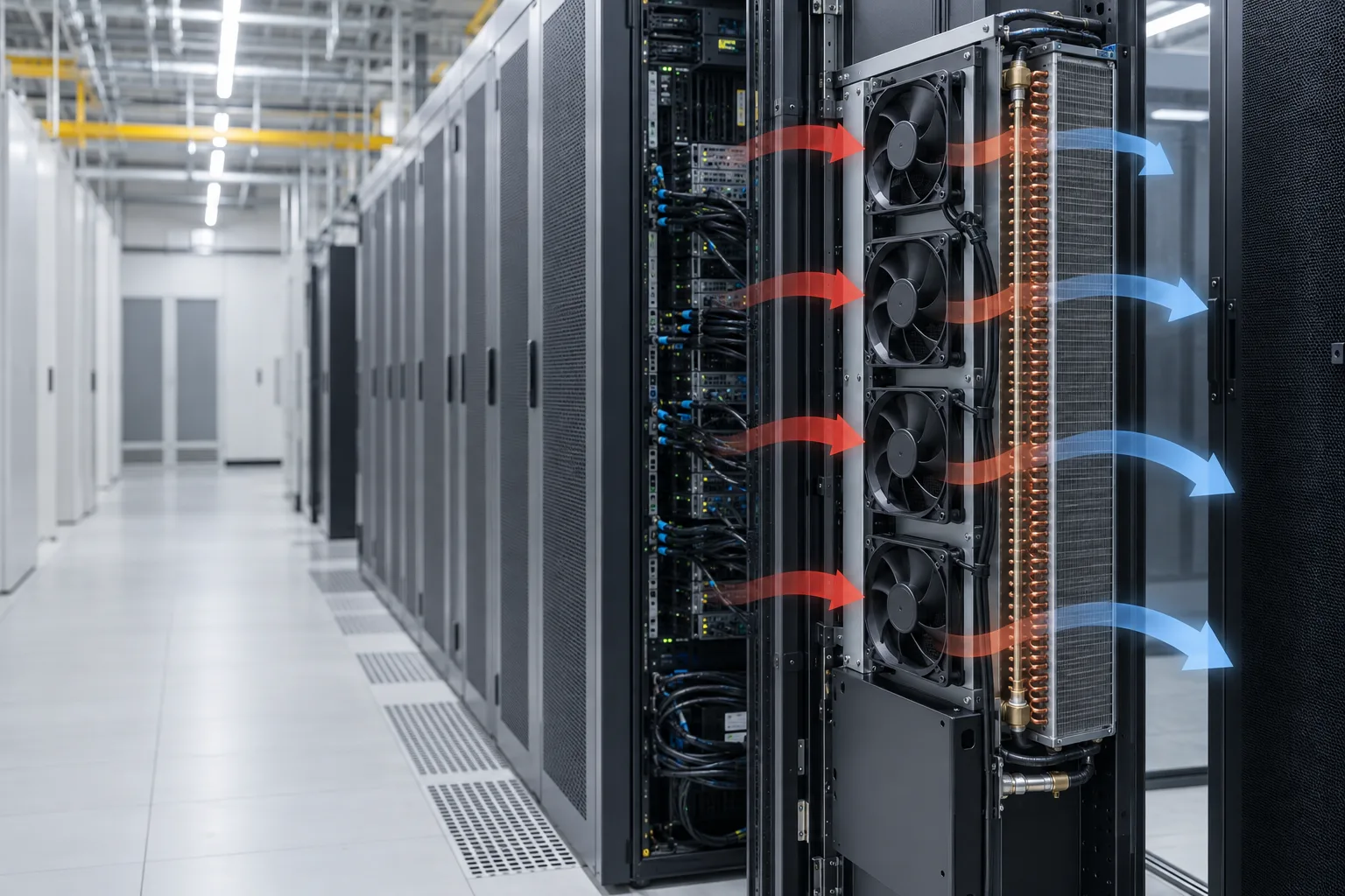
Custom Fans for Active Rear Door Heat Exchangers
An active rear-door heat exchanger depends on a controlled airflow path through the rack door, coil and surrounding data-center system.
MEGA Tech supplies custom cooling fans and air-path engineering support for active RDHx projects. We help engineers review airflow, static pressure, control interfaces, acoustics, vibration and sample performance before a fan is released into production.
The fan should be selected for the installed operating point, not only by frame size, voltage or free-air airflow. A fan that performs well in free air may deliver much less airflow after the heat-exchanger coil, grille and other restrictions are installed.
For system context, read our RDHx airflow overview and review the AI data-center cooling application page. This guide focuses on the custom fan and air-path interface within that larger system.
What the RDHx Fan Must Do
The fan has to work with the whole door assembly, not in isolation.
An active rear-door heat exchanger moves rack exhaust air through a heat-transfer section before the air returns to the data-center room. The design review should include rack exhaust airflow, coil pressure drop, protective grille resistance, door-module arrangement, operating temperature, control signals, acoustic limits and service access.
The first requirement should describe airflow together with static pressure. Maximum airflow and maximum pressure are endpoint values; neither is the installed operating point.
- Required airflow per fan or door module
- Heat-exchanger coil pressure drop
- Grille, filter and transition resistance
- Voltage, PWM, FG and RD requirements
- Noise, vibration and maintenance constraints
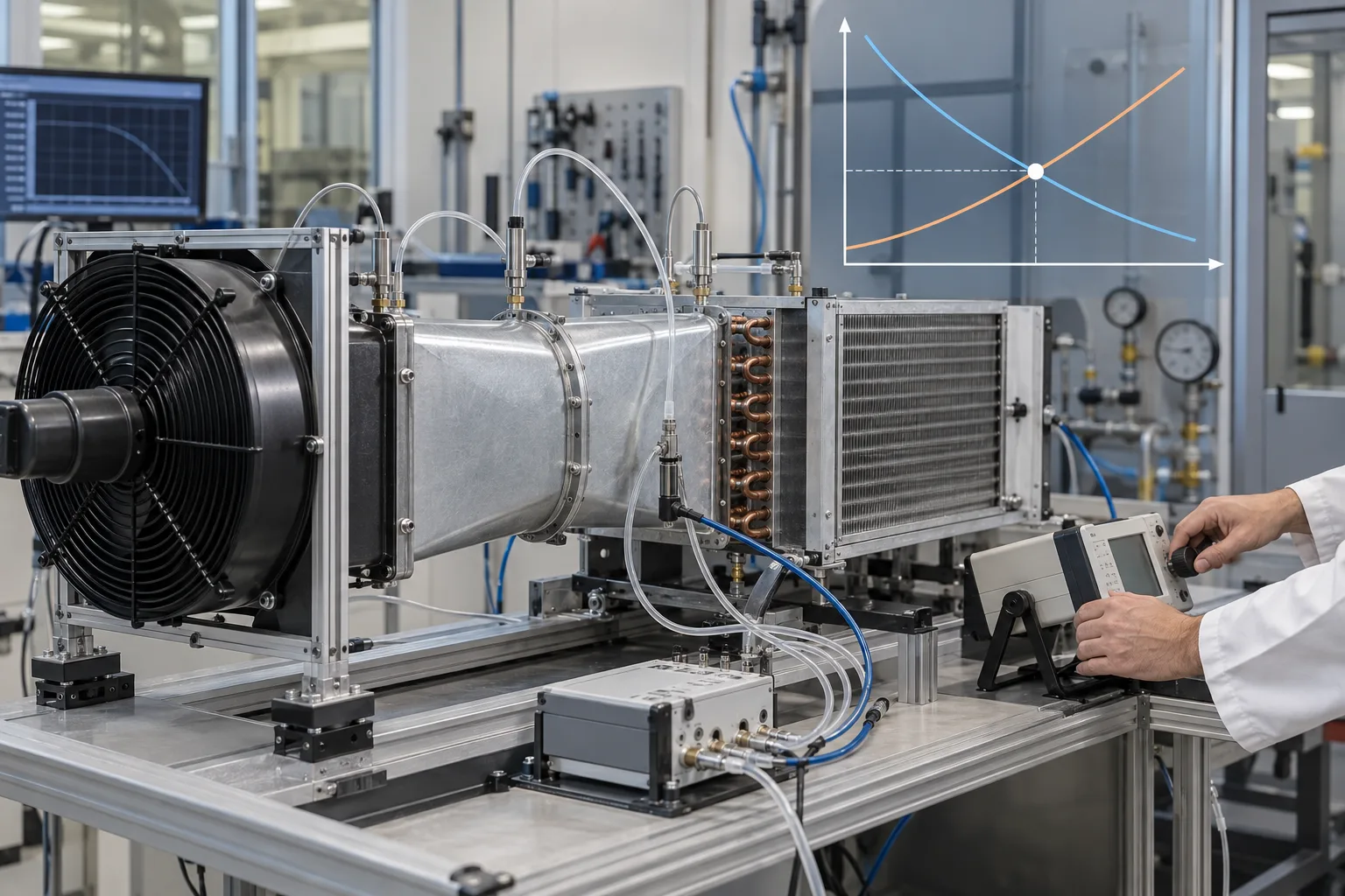
Airflow, Pressure Drop and the Operating Point
The useful question is how much airflow the fan maintains at the resistance of the installed RDHx air path.
The operating point is where the fan performance curve intersects the resistance curve of the RDHx assembly. Resistance may come from the coil, door grille, protective mesh, sealing features, transition sections and rack exhaust restrictions.
The coil pressure-drop curve is strongly preferred. If it is unavailable, provide the required airflow, coil information, fan arrangement and installation drawings so the pressure requirement can be estimated and then verified with a representative sample.
Numerical fan performance values should be taken from the relevant MEGA Tech laboratory record. Until those records are attached to the design review, use a data-entry table rather than a guessed specification.
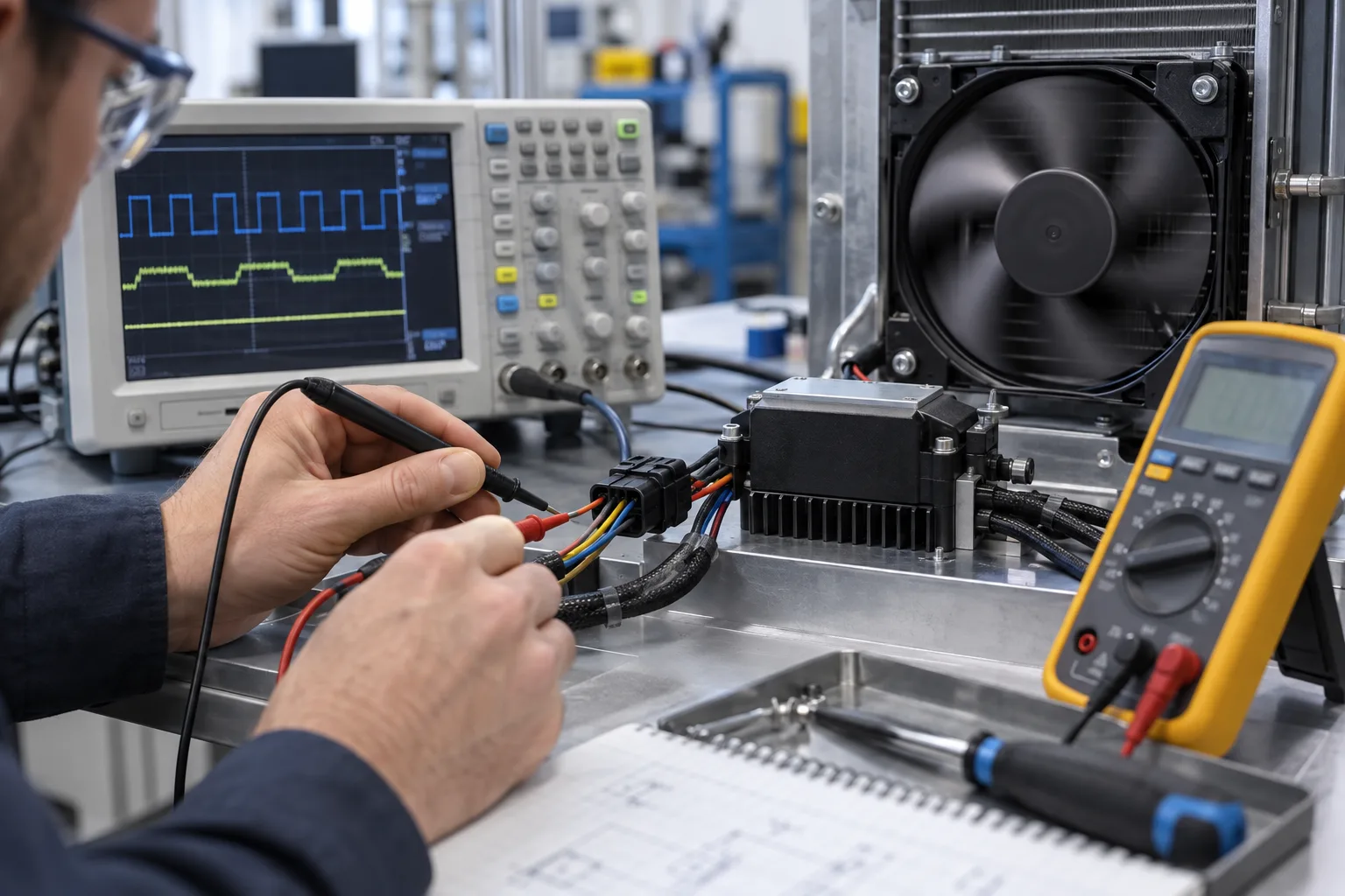
PWM, FG, RD and Control Interface Checks
Mechanical interchangeability does not prove electrical compatibility.
Check supply voltage and tolerance, startup behavior, PWM frequency and duty range, speed response, FG or tachometer pulse behavior, RD or alarm logic, locked-rotor detection, connector pinout and cable access.
The interface should be checked on the customer's controller or a representative test setup. Availability and electrical behavior must be confirmed for the selected fan rather than assumed from another model.
- Supply voltage and tolerance
- PWM command and minimum duty
- FG or tachometer behavior
- RD or alarm output logic
- Connector pinout and service access
Single-Fan Failure and N+1 Airflow
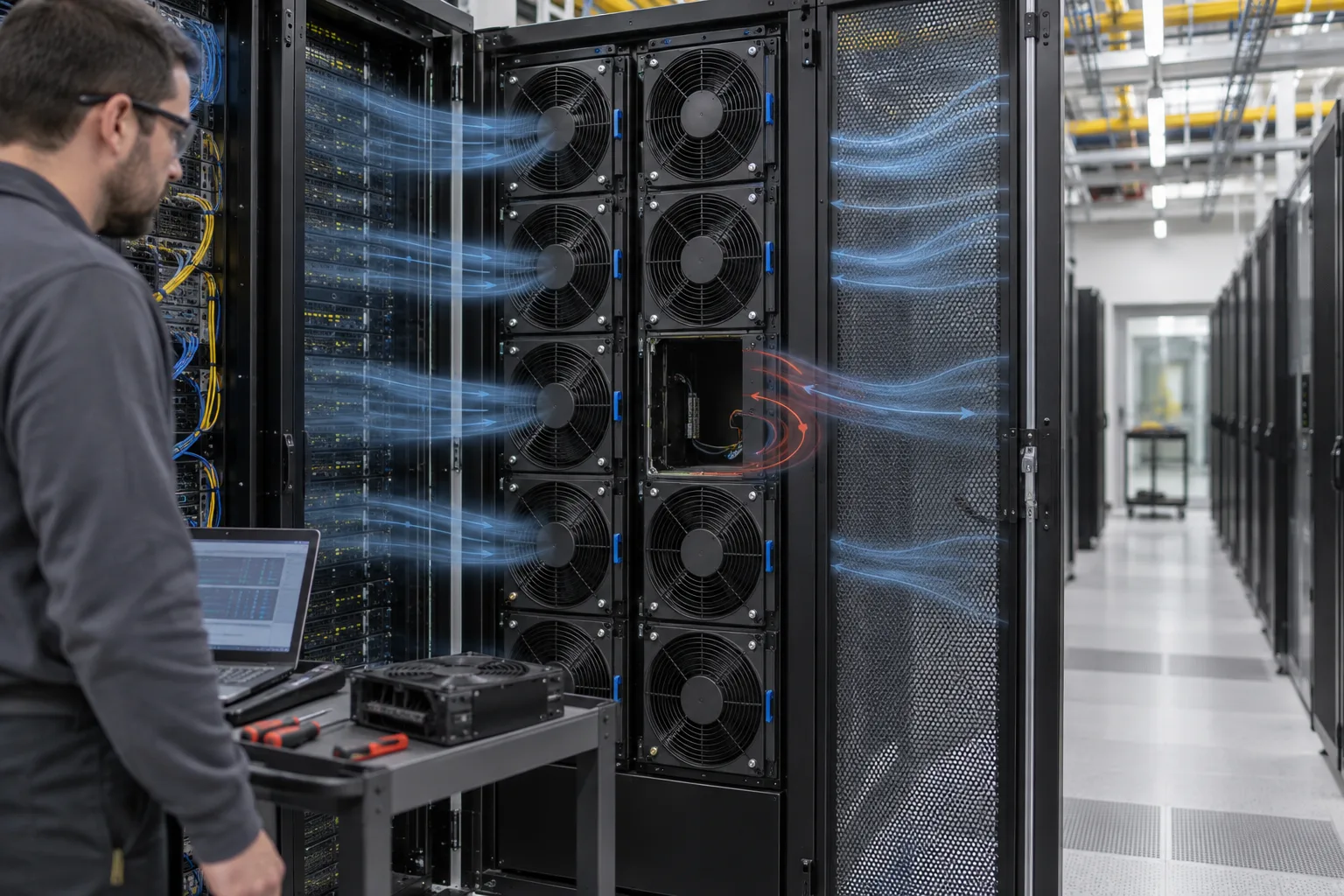
N+1 is a system-level requirement that must be checked with a fan module stopped or isolated.
The review should record remaining airflow, pressure distribution, possible reverse flow through the failed module, controller alarm behavior, rack outlet temperature change and replacement access.
An individual fan datasheet cannot confirm the N+1 result. The result must come from a physical or representative test in which the relevant module is stopped and the airflow path is measured. Do not publish an N+1 result until the test record exists.
Noise, Vibration and Maintenance Space
The installed air path can change acoustic and vibration behavior compared with a free-air test.
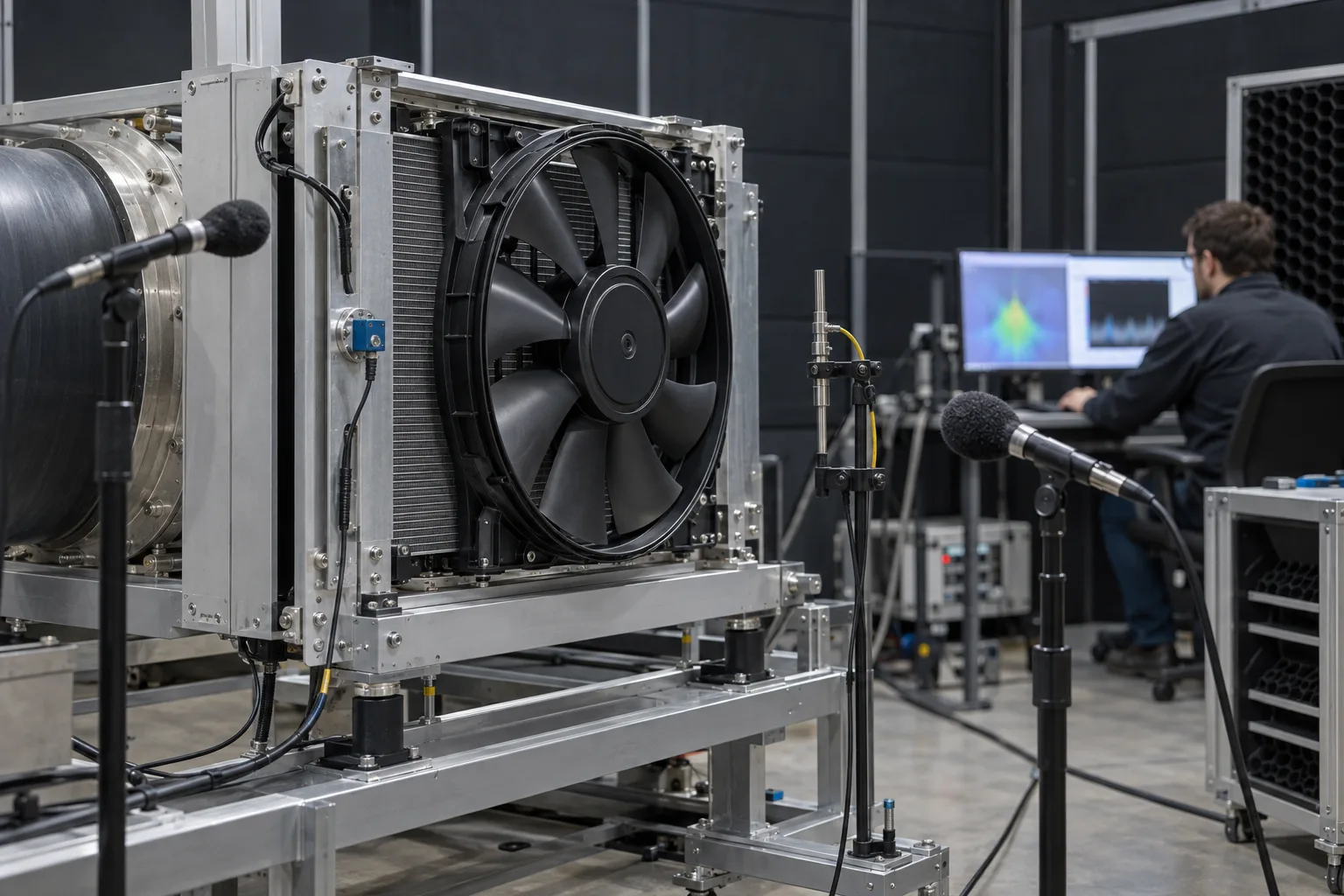
Review fan speed, blade-pass tones, coil and grille turbulence, door-panel resonance, mounting stiffness, imbalance, bearing vibration and fan-to-fan interaction at the actual airflow and pressure point.
Maintenance planning should include module removal direction, connector access, cable bend radius, replacement clearance and identification of a failed module. A sample should be checked in a representative air path whenever possible.
Information Required for a First Review
A clear engineering input package makes the first fan comparison faster and more reliable.
Send the fan size and mounting drawing, current fan reference, voltage, required airflow, static pressure or coil curve, PWM/FG/RD requirements, connector and pinout, ambient and exhaust-air temperature, noise target, quantity, duty assumption, installation drawings and any N+1 requirement.
If some information is missing, send the fan label, installation photos and application description first. The missing parameters can then be identified during the review.
- Fan size, mounting and current reference part
- Airflow and static pressure at that airflow
- Voltage tolerance and control interface
- Temperature, noise and environment
- Quantity, duty and N+1 requirement
Sample Validation Process
A representative sample turns a paper selection into evidence for the production design.
First confirm the envelope, voltage, airflow, pressure and control requirements. Then compare candidate fans at the working point, prepare samples with the required connector and mounting arrangement, and check startup, speed control, FG/RD behavior and abnormal operation.
Install the sample in the representative RDHx air path and record airflow, pressure, temperature, control response, noise and vibration. Record open issues before production release.
- Application review
- Candidate selection at the operating point
- Sample preparation
- Bench and interface verification
- Installed-air-path validation
- Design review and release decision
What MEGA Tech Provides
MEGA Tech helps equipment teams move from an RDHx requirement to a fan configuration that can be checked in the customer's application.
Our support may include reviewing airflow and static pressure, comparing fan options by operating condition, checking voltage and control interfaces, preparing sample configurations, supporting fan replacement evaluation and reviewing installation constraints.
Selection is based on the application requirement, not only on the original part number or outline dimension. Two fans with the same external size can differ in airflow, pressure capability, speed control, acoustic behavior, electrical interface and failure response.
MEGA Tech does not supply the complete RDHx, coil, liquid loop, cabinet structure or rack safety system. Those remain with the system integrator.
Engineer FAQ
Use these questions to define the next measurement or sample-validation step.
Q: Can MEGA Tech supply a complete rear-door heat exchanger? A: No. MEGA Tech supplies custom cooling fans and air-path engineering support; the complete RDHx and liquid-side system remain with the system integrator.
Q: Can a same-size fan replace the original fan? A: Not automatically. Airflow, static pressure, voltage, control, acoustics, vibration and installed performance must also be checked.
Q: Do you need the coil pressure-drop curve? A: It is strongly preferred. If unavailable, provide the required airflow, coil information and installation details for an estimate and sample plan.
Q: Can you support PWM, FG and RD? A: These interfaces must be confirmed for the selected fan and checked against the customer's controller.
Q: Can you validate N+1 operation? A: MEGA Tech can support fan-level and air-path validation planning. N+1 acceptance remains a system-level responsibility.
Q: What should I send for a technical review? A: Send fan size, voltage, airflow, static pressure or coil curve, quantity, control interface, noise target and installation constraints.
Related guides
View all → Network Switch Cooling
 Fan Selection: Match Chassis Pressure to Rack Airflow
 Cooling Fan Bearing Selection
Ball vs Sleeve vs Fluid Dynamic Bearing Fans: Choose by Temperature and Duty
 Axial vs Centrifugal Fans