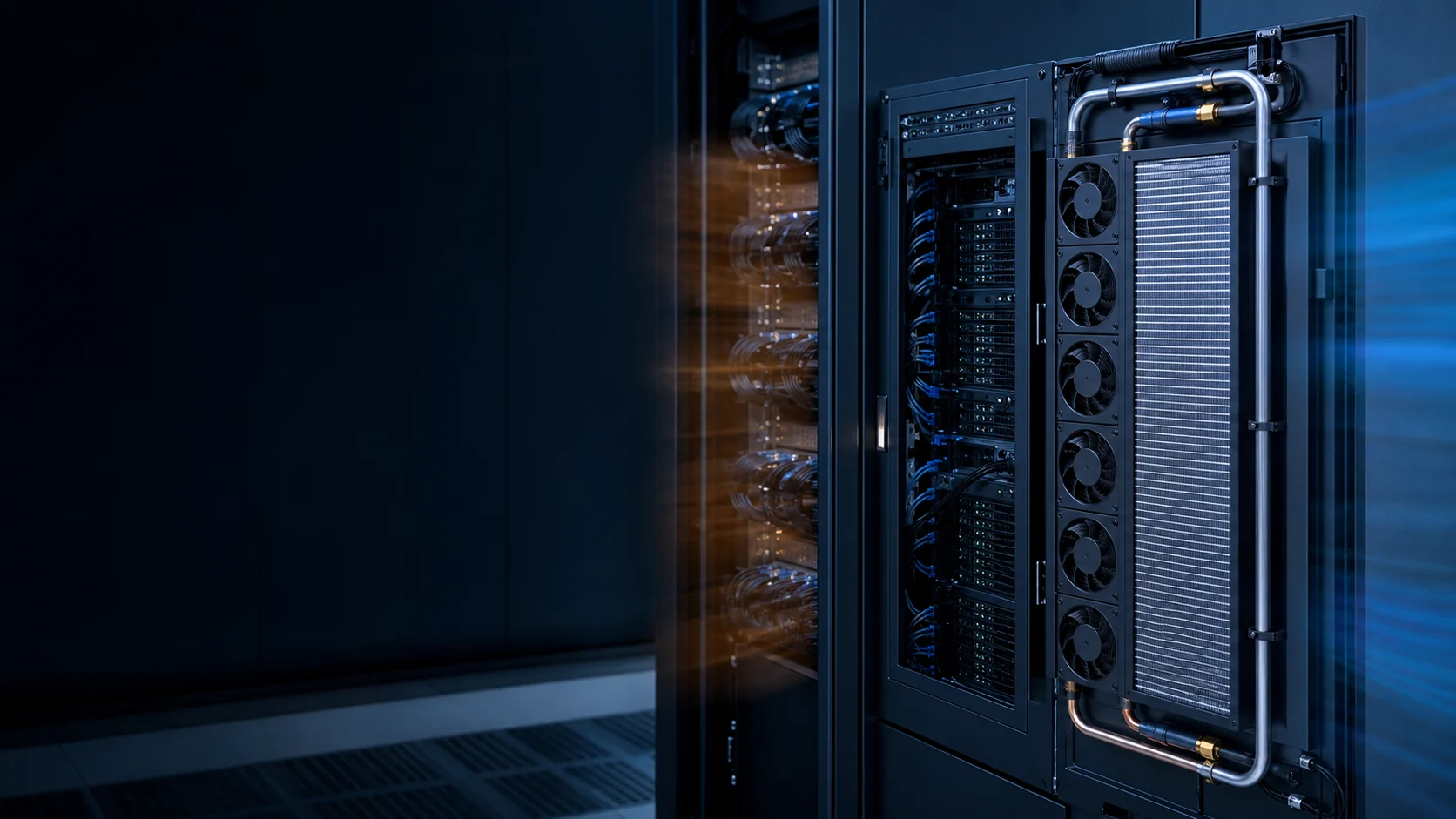
Remove heat close to the rack
A rear-door heat exchanger (RDHx) is mounted on the rack exhaust side to capture heat in water before it spreads into the room.
It is often considered when rack density makes a room-air-only strategy hard to scale. RDHx is 'air-assisted liquid cooling': servers stay air-cooled, but most of the exhaust heat is picked up by a water coil in the door, so the air returning to the room can approach room-neutral conditions rather than hot-aisle temperature. That heat capture is the property that makes the approach attractive: it can greatly reduce the rack's direct sensible-heat load on room CRAC and CRAH units, but bypass air, leakage and door limitations still have to be managed.
Compared with in-row cooling at similar density, the door uses the rack's rear plane rather than consuming a separate floor position. The air leaving the rack can be returned close to room-neutral conditions instead of being discharged as a hot plume, but the result depends on coil selection, water temperature and airflow. Because it replaces a standard door rather than rewiring servers, it can be deployed incrementally in an existing white space: rack-by-rack, row-by-row, subject to water distribution and service access.
The economics follow from that. Public vendor data shows that RDHx capacity is model- and condition-specific: Vertiv's CoolLoop RDHx materials list configurations from 5 to 85 kW per rack, with the actual result depending on door size, airflow, water temperature and water flow. This is a product-family range, not a universal thermal boundary. Beyond the selected door's verified capacity, direct-to-chip cold plates or another liquid architecture may take more of the GPU heat while the air side continues handling the remaining components.
Be equally clear about what it does not solve. For extreme densities or concentrated hotspots, direct-to-chip and immersion cooling hold the higher thermal margins — a door still has to move air past the whole rack. The value case also weakens where rack heat output is highly variable or heterogeneous: some doors end up underutilized while others saturate, and room- or row-level strategies may use that capacity better. And per-rack pricing compounds: a few hundred racks is a straightforward funding conversation; tens of thousands of doors is a hyperscale procurement with its own logistics. RDHx earns its keep where rack configurations and workloads stay reasonably consistent over time.
It is not a stand-alone answer. The door, rack, server airflow path, water loop, control system and service process all influence the result. Treat it as one component inside a cooling architecture, not a replacement for planning the air and water sides around it.
Passive vs active — the airflow choice
The first design decision is whether the door adds its own fans.
A passive RDHx has no powered parts in the door. Server fans push exhaust air through the coil. Fewer components, no door power draw, and a hinged door like a normal cabinet — but performance is tied directly to the rack airflow path and the coil's pressure drop. Under a load spike, passive airflow is literally 'whatever the servers provide': the fans ramp on their internal inlet-temperature logic, and the door inherits the result.
An active RDHx adds EC fans in the door to control airflow and pressure. That makes mixed-density rows and fast load swings more predictable, at the cost of door fan power and one more control loop with its own failure modes. Published product data shows that door-fan input can range from hundreds of watts to kilowatts depending on capacity and duty, while the same product family may publish cooling capacities up to 85 kW per rack. Treat every figure as attributed model data: verify the specific coil, water temperature, airflow and fan input at your operating point.
The honest comparison is more subtle than 'active is better'. Published operator discussion finds the total-facility energy difference between the two can be modest in some environments, because the result depends on how the server fans are tuned, how the coil is sized and where the coolant temperature sits. What the active door buys is predictability: a defined airflow through the coil independent of server-fan behavior, which matters most when rack loads are volatile — common in AI training clusters.
One mechanical detail belongs in the review for active doors: they are heavy hinged assemblies with spinning fans, so door-fan imbalance can translate into rack sway and connector fretting over time. Ask how the door is balanced and what the mounting hardware tolerates before accepting the higher-density figures.

The two linked flow paths
Air side and water side must both be designed — optimizing one while neglecting the other creates a restriction problem.
On the air side, the coil adds resistance that the server or rack fan system must overcome. On the water side, available temperature, flow, pressure drop, connection routing and leak management set the heat-removal capability. A cold water loop cannot fix a door whose coil starves the servers of airflow.
The water side has simple physics behind it: heat captured equals mass flow times specific heat times the water temperature rise across the door. As a worked calculation, 20 US gallons per minute rising 3.8°C transfers about 20 kW for water at typical engineering assumptions. This is an example, not a recommended setpoint; with supply/return temperatures and a flow reading, the same arithmetic lets a site team check what the door actually removes without trusting a single gauge.
But water-side math does not automatically equal rack heat removed. Bypass air that short-circuits the coil and recirculation that sneaks warm air back to the inlets both inflate the water-side reading relative to what the rack experienced. Correlate at least three measurement points — rack exhaust, door discharge air, and the hot aisle — before declaring a capacity number real.
A successful installation balances both paths. Water temperature, flow and pressure drop are vendor- and model-specific; use the door datasheet rather than transferring a range from another coil. As a practical reference, the cited Vertiv product family covers 5-85 kW per rack, while the heat-balance equation lets the site team check the actual result. Every number is meaningless if the air side cannot deliver the exhaust to the coil. Vendor leaving-air conditions are behavior on a curve, not a constant.

Coil pressure drop is the red-line interface
The coil's pressure drop is the single value that can break the rest of the system.
In a passive door the coil pressure drop (△P) must sit on the server fan curve, not above it. Too much △P and the server fans cannot deliver design airflow; the cabinet pressurizes, internal paths seal off, and hot exhaust recirculates back to the inlets — the same short-circuit pattern seen in poorly planned enclosures.
Active doors supply the pressure with their own EC fans, so they are less dependent on server-fan headroom. But the coil still sets the total system resistance, and the door fans now draw their own power — so the trade is moved, not removed.
Two airflow-management defects quietly erode any door's effective capacity, and both are common in real rows. Missing blanking panels let bypass air skip the coil entirely; uneven rack population creates recirculation paths that drive server-fan ramps and destabilize inlets. Localized heat flux — GPUs concentrated in one zone — produces hot spots even when the average rack kilowatts look acceptable. Treat blanking, sealing and population balance as part of the RDHx system scope, because the door cannot cool air that never reaches it.
Server fans still matter
A rear door changes where exhaust heat goes; it does not remove the need for an intentional path through each server.
Server-level fans still move air across heatsinks, power supplies and chassis components. In a passive door they are the only thing moving air through the coil — and under AI workload spikes it is their ramp behavior, governed by internal inlet-temperature logic, that decides how much airflow the coil receives while the step change is happening.
In an active door they still set the upstream pressure the door fans work against, and weak internal fans still limit what the door can recover. Hardware teams should keep validating chassis fan performance while coordinating rack-level requirements with the infrastructure team. The door is a partner to the server fans, not a substitute for them.
For planning, define three load numbers per rack rather than one: sustained, 95th-percentile and peak. Response time — not steady-state capacity — is usually the bottleneck during a spike, and unless the door and water loop have been proven at your step size, the safe assumption is that some portion of short spikes passes through to the room.
This is also where the hardware team and the facility team need a written contract: the exhaust condition — airflow, temperature, and how both move under load steps — is the data the door's coil selection depends on. Chassis-level fan validation should therefore be shared, not siloed. A rack spec that states the exhaust envelope lets the infrastructure side pick or tune a door with evidence instead of assumptions, and it is exactly the kind of interface a cooling-fan partner should be able to certify.
Condensation gate — keep water above the dew point
Condensation control is the first engineering gate for any chilled-water door.
ASHRAE TC 9.9 recommends keeping facility water temperatures at least 2°C above the room dew point, with telemetry and valve control to hold that margin. Where supply water would fall to or below the dew point, a coolant distribution unit (CDU) creates a warmer secondary loop so the coil surface stays above dew point.
The coil, valves and uninsulated fittings all sweat if they cross the dew point, so the buffer is deliberate — not a razor-thin setpoint relying on a single sensor. Sensors have error and conditions drift; a 2°C margin on paper can become zero in an economizer season or a humidity excursion. Note the second-order effect: the dew-point margin caps how cold the water may run, which can reduce the door's available capacity versus a colder datasheet condition. Check capacity at your real, dew-point-constrained water temperature band rather than assuming a published rating transfers unchanged.
Insulate the distribution and place leak detection where condensate would first appear — the low points, hinge bases and hose couplings. A common field practice pairs sensing rope with an automatic solenoid shut-off on the door's water supply, so a drip isolates itself before anyone is paged. On the loop side, variable-speed pumps that trim flow when rack load drops prevent the opposite failure: over-cooling a light load down toward the dew point.
Plan service and failure conditions
A rack door is also a physical service component with operational failure modes.
Hose routing, quick-disconnect couplings, door-opening clearance, leak detection, alarms and maintenance access must be resolved before installation. Most retrofit risk lives in routing and isolation, not the door hardware — a hall that cannot be serviced one door at a time is a hall that will be drained to fix one leak.
Where a CDU sits in the chain, decide what it decouples: a secondary loop stabilizes temperature, flow and alarms at row level and isolates the doors from facility-water quality and pressure surprises. That is an operating decision, not just a plumbing one — it changes who reacts to which alarm.
Define the failure plan up front: loss of water flow, loss of controller signal, loss of BMS comms, or a required service event. Set trip versus advisory logic and name an owner for each excursion, or the pilot looks good and scale becomes painful.
Instrument the pilot as if it were production. A one-row pilot with full telemetry — dew point pairs, loop temperatures, flow, leak rope — proves the operating model on a small blast radius and produces the tuning the full hall will inherit. A pilot run with temporary sensors proves nothing except that water can flow through a coil.
- Leak detection at low points and at every connection or coupling zone
- Isolation valves so one door can be serviced without draining a hall
- Pump status, flow and differential-pressure telemetry on the loop
- Room dew point from multiple sensor pairs, plus supply/return temperatures on both loops
- Trip vs advisory logic for dew-point margin, pump failure, leak detected and comms loss
What engineers and buyers should ask for before approval
The decision is not a brochure-capacity comparison. It is an evidence review across the rack air path, water circuit, controls and service plan.
Thermal engineers normally start with the installed air interface: the coil pressure-drop curve, the server or rack fan curve, the actual rack population and the required inlet-temperature margin. That is the evidence needed to decide whether a passive door is viable. In one specific Vertiv DCD product family, active assistance is recommended around 25 Pa and passive use above 30 Pa requires test confirmation; those are vendor-specific guidance values, not a universal RDHx threshold. The same manual says fan performance, hot/cold-air separation and cabinet leakage can move the decision in either direction.
For procurement and operations teams, the comparable line items are less glamorous but equally important: capacity at the stated water temperature and flow, door fan input at the stated speed, pressure drop on both air and water sides, door depth and opening clearance, hose and quick-disconnect arrangement, monitoring interfaces, spare-module availability, maintenance access and failure response. A capacity claim without those test conditions cannot be compared fairly.
The approval pack should record one normal condition, one high-percentile condition and one upset condition such as a workload step, door-fan fault or reduced water flow. It should also state who owns each alarm and what action follows. That converts a high-density cooling purchase from a nominal kW number into an operating system the site can commission and service.

| Review area | Evidence to request | Why it changes the decision |
|---|---|---|
| Air-side fit | Coil pressure-drop curve and populated-rack/server fan curve | Shows whether passive airflow has enough headroom at the real operating point. |
| Thermal capacity | Capacity map with water supply temperature, flow, rack airflow and entering-air condition | Avoids comparing headline kW values measured at different conditions. |
| Controls | Fan, valve, flow, temperature and alarm logic including loss-of-comms behavior | Defines how the system reacts to workload steps and faults. |
| Physical service | Door depth, opening clearance, hose bend radius, quick disconnects and isolation method | Determines whether a single door can be serviced without risking the row. |
| Acceptance test | Normal, high-percentile and fault-state measurement plan | Proves cooling performance after installation instead of at a factory-only condition. |
Develop the air-side fan around the rack interface
A rear-door project still needs a fan matched to the rack, coil, control system and service plan.
The heat exchanger does not remove the need for a carefully selected air-side fan. Passive doors depend on the server fans, while active doors add their own fan modules. In both cases, the fan must work with the rack exhaust envelope, coil pressure drop, available space, noise limit, voltage and control architecture. MEGA Tech can support the air-side portion from requirement review through a tested sample.
For an active door or related cooling module, the customization review can include frame size and thickness, airflow and static pressure at the installed coil, speed range, PWM or 0-10 V control, FG or alarm feedback, connector and cable length, bearing choice, rotation direction, mounting and environmental protection. If a catalogue configuration does not match the door, coil or rack, we can develop a practical sample around those interfaces instead of forcing the system to fit a generic fan.
The sample should be evaluated with the actual or representative coil, grille, plenum and controller, including sustained and peak rack loads. We check pressure margin, airflow, temperature response, noise, control behavior and service replacement. Once the customer approves the configuration, it can move into reliable volume production as part of a repeatable door or rack cooling platform.
- Define the rack exhaust, coil resistance, water conditions, noise and electrical targets.
- Customize the air-side fan's size, control, feedback, wiring and mounting details.
- Validate the sample under representative rack load and pressure conditions.
- Transfer the approved fan configuration into stable production and service supply.
Engineer FAQ: Rear-Door Heat Exchanger Airflow and Fan Interfaces
RDHx performance depends on the coupled air path, water loop, rack load and condensation-control strategy, not capacity on a brochure alone.
Q: When is a passive RDHx suitable, and when is an active door worth considering? A: A passive door relies on server fans and is attractive when the rack has verified exhaust pressure headroom and a stable load. An active door adds its own controlled fans when airflow must be more predictable across variable or mixed-density loads, but it adds power, controls, noise and failure modes. Compare both at the actual coil pressure drop and rack duty.
Q: Can an RDHx remove its published kW rating from every rack? A: No. Capacity depends on coil, water supply and return temperatures, water flow, exhaust airflow, inlet conditions, bypass and the measurement boundary. A published product-family range is not a universal rack limit. Validate the selected door at sustained, high-percentile and peak exhaust conditions.
Q: Why is coil air-side pressure drop critical in a passive door? A: The server fans must overcome the added coil resistance. If the door pressure drop moves the server fan operating point to lower airflow, the door may reduce rather than improve thermal performance. Plot the door pressure-drop curve against the actual server or rack fan curve with the rack populated and the filter or grille in its required condition.
Q: Does water-side heat transfer prove that the rack is adequately cooled? A: No. Water-side heat balance shows how much heat entered the loop, but bypass air can avoid the coil and recirculation can return warm air to the rack inlet. Correlate water flow and temperatures with rack exhaust temperature, door discharge temperature, inlet temperature, airflow and component temperatures.
Q: How should condensation risk be controlled? A: Keep the relevant coil, water circuit and fittings above the room dew point with the project-defined margin, use dew-point and supply-temperature telemetry, and validate the response to humidity or control excursions. If the facility water is too cold, use an appropriate secondary loop or CDU strategy rather than relying on one sensor reading.
Q: What should be checked before choosing an active-door fan? A: Request the fan P-Q curve at the door coil resistance, input power across the speed range, acoustic data, control interface, fault behavior, environmental rating, mounting and service method. Check normal, peak, loaded-filter or loaded-coil and one-fan-out conditions if the door uses multiple modules.
Q: Does an RDHx remove the need to validate server fans? A: No. Server fans still establish the airflow through the chassis and, for a passive door, through the coil itself. Validate chassis inlet temperature, internal component temperatures, fan speed, pressure, airflow and load-step response with the actual door or a representative resistance.
Q: What should a production-representative fan sample prove? A: Use the real or representative door coil, grille, plenum, controller and rack exhaust condition. Measure pressure, airflow, temperature response, noise, current, RPM or feedback, PWM or 0-10 V behavior, fault response and service replacement before approving the configuration for repeat production.
- Tie every numerical answer to voltage, speed, temperature, mounting and test condition.
- Separate catalogue maximums, engineering estimates and measured application results.
- Use the FAQ to define the next measurement or sample-validation step.
Interface review checklist
A written interface review keeps rack, server and facility responsibilities clear — and states the MEGA Tech scope.
Use the checklist below at design review. It is the same list that prevents the silent failures described above, and it is the handoff document between the hardware team and the facility team. Ask for performance evidence at your water temperature band and flow range, under all three load numbers — sustained, 95th-percentile and peak — rather than accepting a nominal-case datasheet.
- Target rack load (sustained / 95th-percentile / peak) and expected exhaust condition
- Available water-loop capacity, temperature band and connection route
- Air-side pressure drop at the installed rack versus the server/rack fan curve
- Dew-point margin strategy: facility water directly, or CDU secondary loop
- Heat-to-water correlation: rack exhaust vs door discharge vs hot-aisle measurements
- Leak detection, access and maintenance procedure
- Commissioning measurements and the ongoing monitoring owner