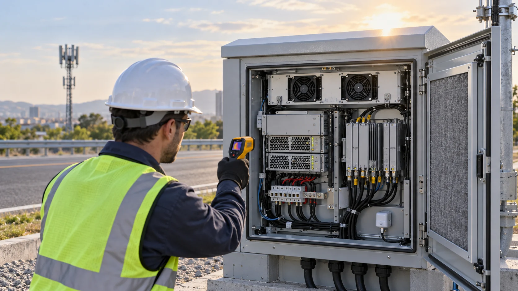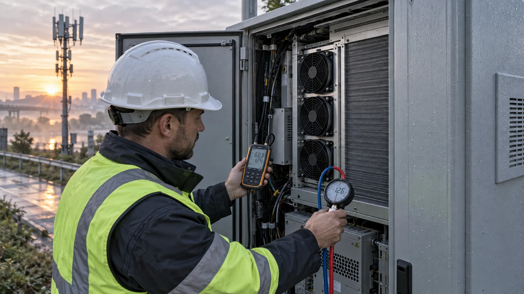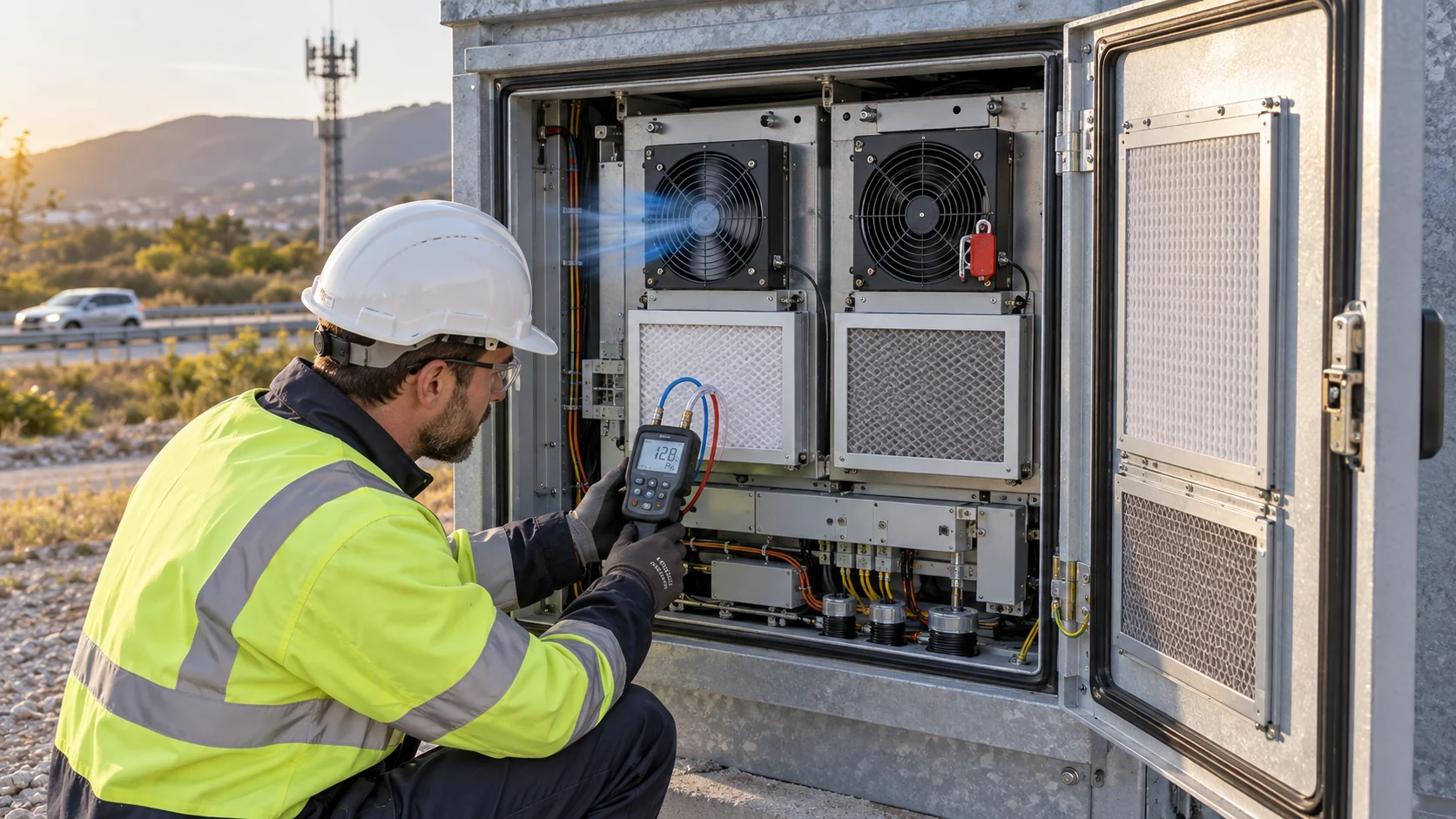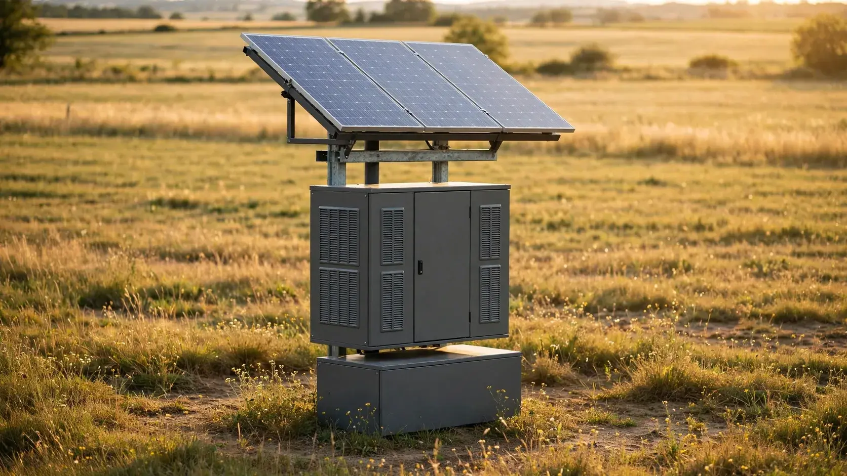
The fan is the only load that runs all night for free heat
On a grid cabinet the fan is a rounding error. On a solar powered cabinet every fan watt is stored sunlight, and it is drawn hardest at exactly the hours the array produces nothing.
A grid-fed telecom cabinet pays for cooling in currency, and currency is cheap and continuous. A solar powered cabinet pays in photovoltaic watts and battery amp-hours, and both of those are capped on the day they were installed. The fan therefore competes line by line with the radio it is protecting, and the competition is decided in watt-hours per day, not in airflow cfm.
The timing makes it worse. Thermal load and solar generation follow the same daily curve: the cabinet is hottest in the late afternoon, carries its heat into the evening, and needs the most airflow after sunset when the battery bank is already servicing the electronics alone. A fan that runs continuously at full speed is the least interesting answer to that problem, but it is still the default in many quotations.
Every number below is worked from one reference site so the arithmetic can be checked: an off-grid microwave relay cabinet, 600 x 600 x 1200 mm, a double-wall enclosure with 25 mm of insulation, 150 W of average electronics dissipation, an insulated wall coefficient of 1.5 W/m2K, 40 C ambient with a shaded white finish, and two 80 x 80 x 25 mm DC fans at 4.8 W each.
The budget lives in watt-hours, not in watts
A fan datasheet quotes watts. An off-grid energy system is sized in watt-hours per day. The conversion is a multiplication by hours that most quotations never perform.
Daily energy is power times hours, and for continuously running loads the hours are 24. A 10 W fan therefore does not add 10 W to the design problem; it adds 240 Wh to every day of the site's life, and it adds them to the battery-backed portion of the day, because at night the only source is storage.
That placement matters twice. First, the autonomy calculation multiplies the whole daily budget - fan included - by the number of sunless days, so the fan's contribution is magnified by the autonomy target. Second, every watt-hour charged into the bank suffers the round-trip efficiency of the chemistry, so a lead-acid site pays roughly 1.18 Wh of array energy per Wh of fan, against 1.05 Wh for lithium.
The table below is the whole argument of this article in one place: the fan is a few per cent of the daily budget, but it appears in the autonomy reserve, in the array sizing and in the round-trip losses, three times each day, forever.
| Load | Power | Hours | Daily energy | Share |
|---|---|---|---|---|
| Radio and control electronics | 150 W | 24 h | 3,600 Wh | 96.6 per cent |
| Fans at full speed, no control | 9.6 W | 24 h | 230 Wh | 6.4 per cent of electronics |
| Fans, thermostatic duty | 9.6 W day / 2.1 W night | 24 h | 125 Wh | 3.5 per cent of electronics |
| Total with thermostatic control | 159.6 W average | 24 h | 3,725 Wh | 100 per cent |
Fix the climate class and the autonomy target before any fan is chosen
The environmental class sets how much cooling the site needs; the autonomy target sets what that cooling costs. Neither number belongs to the fan vendor, and both must be on the thermal specification first.
For the environment, ETSI EN 300 019-1-4 does the same job here that it does for every outdoor cabinet: class 4.1 fixes the high air temperature at +40 C, the low end at -33 C, solar radiation at 1120 W/m2 and air pressure down to 70 kPa. The low-temperature corner is not a cooling number, but it is a fan number - cold-start torque and bearing grease at -33 C decide whether the fan is alive on the first morning of winter.
For the energy side, the autonomy target is a business decision expressed in days: how many consecutive sunless days must the site ride through on storage alone. Remote telecom practice sits between 3 and 5 days; 3 days is defensible where diesel service exists, 5 days where it does not. The autonomy figure multiplies the entire daily budget, so each watt the fan burns raises the battery reserve and the array together.
Charge efficiency belongs in the same paragraph because the array has to replace what the loads took out plus the storage losses: round-trip efficiency is roughly 85 per cent for deep-cycle lead-acid and 95 per cent for LiFePO4, and that difference alone shifts the required array by about 12 per cent.
| Decision | Typical value | What it drives |
|---|---|---|
| Environmental class (ETSI 300 019-1-4) | Class 4.1: -33 to +40 C, 1120 W/m2 | Cooling duty, cold-start, bearing specification |
| Autonomy target | 3 to 5 days | Battery reserve scales the whole daily budget |
| Round-trip efficiency | 0.85 lead-acid / 0.95 LiFePO4 | Array size for the same delivered Wh |
| Peak sun hours at the site | 4 to 5 h/day design value | Array watts per daily Wh |
What the fan must remove on the reference site
The thermal half of the problem is conventional: 96 W of heat, 44 m3/h of air, two 80 mm frames. The interesting half is what those two frames cost the energy system.
The insulated double wall is deliberate: it keeps solar gain out, and it also keeps the enclosure's own rejection low. With an overall coefficient of 1.5 W/m2K, 3.6 m2 of external surface and a 10 K rise between internal air limit and effective ambient, the walls remove about 54 W. The remaining 96 W of the 150 W load has to leave with the air.
Airflow follows from the sensible-heat equation: volume flow equals heat divided by the density, specific heat and permitted air-temperature rise. Allowing 8 K of air rise inside the cabinet gives about 41 m3/h at sea level, or about 45 m3/h corrected for the lower density at a 50 C operating temperature. Two 80 x 80 x 25 mm fans at roughly 50 m3/h each at their working point cover it with margin for filter fouling.
Both fans run continuously on the reference site because the load never switches off - a radio idles warm even when traffic is zero. This is the difference from a day-cabinet: the fan duty factor here is 100 per cent at night by design, and the only remaining lever is speed.
| Quantity | Value | Note |
|---|---|---|
| Internal dissipation | 150 W | Radio plus control, continuous |
| Wall rejection (insulated, 1.5 W/m2K) | 54 W | 3.6 m2, 10 K rise to effective ambient |
| Heat for the fans to remove | 96 W | The wall cannot take more without losing solar protection |
| Required volume flow | about 45 m3/h at 50 C | 8 K air rise, density corrected |
| Selected frames | 2 x 80 x 80 x 25 mm, 4.8 W each | About 50 m3/h each at the working point |
Frame choice is an energy decision, not an airflow decision
Any of four frame sizes can move 44 m3/h. They differ by a factor of three in watts, and watts are what the battery bank is made of.
A large, slow frame moves the same air as a small, fast one at lower power and lower noise, because pressure and power both fall with diameter at fixed flow. In a sealed, filtered cabinet the system impedance is dominated by the screen, louver and filter, so the frame needs static pressure margin as well - but between two frames that both meet the working point, the lower-watt one wins every time on an off-grid site.
Speed control compounds the choice. A frame with PWM or tachometer feedback holds its working point as the filter loads, while an uncontrolled frame simply drifts - its airflow falls with fouling while its watts stay similar. On a solar site the controlled frame is worth its premium in array watts.
The table compares the candidate frames at the same working point. The 60 mm pair is the lowest-watt option at the clean working point, but its static-pressure headroom against a loaded filter is thin and its bearing life is the shortest of the credible frames; the 80 mm pair carries the fouling margin, which is why it is the reference choice. The 40 mm pair is not credible at this duty - its operating point sits too close to stall against any filter.
| Frame (2 required) | Power each | Free delivery | Max static pressure | Bearing life at 40 C | Fan energy per day at full speed |
|---|---|---|---|---|---|
| 40 x 40 x 10 mm | 1.8 W | 15 m3/h | 50 Pa | 50,000 h | 86 Wh |
| 60 x 60 x 15 mm | 2.9 W | 45 m3/h | 70 Pa | 60,000 h | 139 Wh |
| 80 x 80 x 25 mm | 4.8 W | 120 m3/h | 90 Pa | 70,000 h | 230 Wh |
| 120 x 120 x 25 mm | 7.2 W | 260 m3/h | 110 Pa | 75,000 h | 346 Wh |
Where the fan sits in the daily budget
The budget chart makes the scale plain: the fan is invisible next to the radio, until you extend the chart to three sunless days and multiply by a decade of sites.
At full speed the two reference fans take 230 Wh per day - about 6 per cent on top of the electronics. With thermostatic control they take 125 Wh, about 3.3 per cent. Neither number is large on a chart, but both numbers are bought three times: once in the array, once in the battery reserve, and once in the round-trip losses, and both scale with the number of sunless days the specification demands.
The chart also shows the night split, because that is the part the battery pays for alone. During the sunlit hours the array carries the whole load; after sunset the electronics and the fan draw 2,129 Wh from storage in the reference 14-hour night, and the fan's share is small but it is drawn at the deepest part of the daily discharge, where depth-of-discharge limits bite.

The cube law is the biggest lever in the budget
Fan power follows the cube of speed. Dropping to 70 per cent speed saves 66 per cent of the watts - no other line in the energy budget offers a return like that.
The affinity relations for a fixed fan in a fixed system are exact: volume flow scales with speed, static pressure with speed squared, and power with speed cubed. In a cabinet whose impedance is mostly filter and screen, operating points follow the same law, so a fan slowed to 70 per cent still delivers 70 per cent of the flow against 34 per cent of the power.
Thermal duty does not follow the cube law - heat removal is roughly proportional to flow for a fixed load - so the speed floor is set by the worst-case heat, not by the fan. That is what thermostatic control implements: full speed when the cabinet is hot, and a floor of 50 to 60 per cent overnight when the load and ambient both drop, which cuts the night fan energy by three quarters without touching the thermal margin.
The floor matters for another reason: at very low speeds the flow measured through a fouling filter falls faster than the affinity law predicts, because the system's impedance constant shifts as the filter loads. Below about 50 per cent, closed-loop control on a tachometer or temperature is safer than open-loop PWM percentages.
| Speed | Fan power | Share of full power | Energy per day at 24 h | Saved per day |
|---|---|---|---|---|
| 100 per cent | 9.6 W | 100 per cent | 230 Wh | - |
| 80 per cent | 4.9 W | 51 per cent | 118 Wh | 112 Wh |
| 70 per cent | 3.3 W | 34 per cent | 79 Wh | 151 Wh |
| 60 per cent | 2.1 W | 22 per cent | 50 Wh | 180 Wh |
| 50 per cent | 1.2 W | 12 per cent | 29 Wh | 201 Wh |
Night duty is a battery problem, not a cooling problem
After sunset the fan's watts come from storage, drawn at the deepest point of the daily discharge. Two protections belong around that fact.
The first is the low-voltage disconnect hierarchy. When the bank reaches its depth-of-discharge floor during a long sunless spell, the controller sheds load in order of harm: radio first if the site can tolerate an outage, telemetry last. The fan should not be in the first group - a cabinet that overheats while its bank recovers can lose the radio permanently, and at low battery voltage the fans are often the cheapest load to keep running at a reduced speed floor.
The second is the winter corner. At -33 C the fan may need to run in reverse mode to pull warm internal air down across the battery and keep the chemistry above its charge-temperature limit. That duty is minutes per hour rather than continuous, but it is a real energy line in the budget at the season when the array has the least to give, and it is one more reason the low-temperature row of the environmental class belongs on the fan datasheet.
Between those two extremes sits the ordinary night, and the arithmetic there is the reference site's: 2,129 Wh drawn from storage during the 14-hour night, of which 29 Wh is the fan at its 60 per cent floor.

Battery chemistry decides the fan's true price
The same fan watt costs a lead-acid site roughly twice the reserve capacity of a lithium site, and the difference compounds through weight, footprint and replacement cycles.
Deep-cycle lead-acid is conventionally cycled to 50 per cent depth of discharge and delivers about 500 to 1,000 cycles at that depth, with round-trip efficiency near 85 per cent. LiFePO4 is conventionally cycled to 80 per cent depth, delivers several thousand cycles, and returns roughly 95 per cent. For the same usable energy the lead-acid bank is therefore about 1.6 times the nameplate size of the lithium one, and in daily-cycling service it is replaced two to four times over the same years.
Applied to the reference site, three days of autonomy need 11,175 Wh of usable reserve: 22.4 kWh nameplate in lead-acid against 14.0 kWh in LiFePO4. The fan's 125 Wh per day sits inside both numbers - but the array must also repay it through the chemistry's efficiency, which is where the 0.85 against 0.95 difference shows up as a roughly 12 per cent array penalty on the lead-acid site.
None of this makes lead-acid wrong: at low duty sites with generator backup it remains the cheapest per delivered cycle. But the comparison must be made with the fan included, because the fan is the load that never pauses.
| Chemistry | Usable depth | Round-trip efficiency | Nameplate reserve | Array repaying 1 Wh of load |
|---|---|---|---|---|
| Deep-cycle lead-acid (AGM/gel) | 50 per cent | about 85 per cent | 22.4 kWh | 1.18 Wh |
| LiFePO4 | 80 per cent | about 95 per cent | 14.0 kWh | 1.05 Wh |
The filter fowls, the fans slow, the battery runs flat
On a grid site a fouled filter is a service ticket. On a solar site it is an energy event: less flow, hotter air, more fan hours at full speed, and a battery that reaches its floor earlier each evening.
The chain runs in one direction. Fouling raises the filter's pressure drop; an uncontrolled fan drifts back along its curve, delivering less flow; the internal temperature rise grows until the thermostat holds the fans at 100 per cent for longer hours; the daily budget inflates by tens of watt-hours exactly when the site is least able to pay them. A controlled fan with a tachometer holds flow at similar watts, but its power still creeps upward as the working point moves toward stall.
The practical defence is measurement, not optimism. A tachometer signal per fan, a differential-pressure switch across the filter, and a logged cabinet temperature give the site operator three independent signals that the flow is gone before the battery tells them at midnight. Filter replacement then becomes a scheduled line in the energy budget instead of an outage report.
This is also where fan life interacts with the budget: a fan held at high speed against a loaded filter ages faster, and an off-grid site that plans its only fan replacement for year eight may meet it at year five.
Sizing the array: the fan appears three times
The array calculation is published in every off-grid handbook, but the fan's three separate entries in it are not always priced.
Entry one is the daily budget itself: the array must produce the load's watt-hours, fan included, through the site's design peak-sun-hours. Entry two is the autonomy reserve: the battery sized from that same budget is larger by the fan's share, and the array must recharge not only the load but the storage losses. Entry three is the round-trip efficiency, which converts every delivered watt-hour into a slightly larger generated one.
For the reference site the chain runs: 3,725 Wh per day of load, divided by 4.5 design peak sun hours and a 0.75 overall system derate, gives about 1,100 W of array; adding the autonomy-reserve recharge and the chemistry losses lifts the practical specification towards 1.3 kWp on lithium and about 1.45 kWp on lead-acid. The difference between thermostatic and uncontrolled fans is roughly 105 Wh per day - 37 W of array on the lead-acid site, 33 W on lithium - small on a drawing, visible across a hundred-site roll-out.
The correct reading is not that fans are expensive. It is that the fan's cost is paid through three multiplications, and a specification that only counts its nameplate watts will understate it every time.
| Step | Lead-acid | LiFePO4 |
|---|---|---|
| Daily load (thermostatic fan) | 3,725 Wh | 3,725 Wh |
| Load through round-trip efficiency | 4,382 Wh generated | 3,921 Wh generated |
| Array for the daily load | about 1,300 W | about 1,160 W |
| With 3-day reserve recharge margin | about 1,450 Wp | about 1,300 Wp |
| Difference: uncontrolled fans | +37 W | +33 W |
The control hierarchy that pays for itself in year one
Four control stages turn the same two fans from a 230 Wh load into a 125 Wh load, and none of them costs more than one array panel.
Stage one is a thermostat: fans off below a setpoint, on above it. It is nearly free and it removes the shoulder-hour waste. Stage two is PWM speed proportional to temperature, which activates the cube law across the whole daily curve instead of just switching it. Stage three is the night floor: a minimum speed that keeps flow through the filter and prevents condensation pockets, typically 50 to 60 per cent, entered as a separate setpoint rather than left to fall with the temperature.
Stage four is the energy-aware mode: when the battery state of charge crosses a threshold, the controller steps the speed floor down one band and logs it. On the reference site that mode converts the worst sunless evenings from a depth-of-discharge violation into a slightly warmer cabinet, which is usually the correct trade for a radio rated to 55 C internal.
What all four stages have in common is that they live in the site controller, not in the fan. The fan only needs to expose a PWM input and a tachometer output - and that requirement belongs on the purchase order, because it is the difference between an energy budget that can be tuned for ten years and one that cannot.
Failure modes and what each one costs the budget
Every failure mode on a solar site ends in energy terms, because that is the currency the site has.
The table collects the modes seen in off-grid service. Each row names the trigger, the energy consequence and the detection that turns it into a maintenance item. The common thread: on a grid site most of these rows are comfort problems, and on a solar site every one of them is charged to the battery.
| Failure mode | Immediate effect | Energy consequence | Detection |
|---|---|---|---|
| Filter fouls | Flow drops, internal rise grows | More hours at full speed: tens of Wh per day | Tachometer below floor, differential-pressure switch |
| One fan fails | Half the flow, 44 m3/h becomes marginal | Survivor runs flat out, ages early | Tachometer signal lost on one channel |
| Fan stalls against loaded filter | No flow, watts still drawn | Pure loss plus overheat risk | Current with zero tachometer |
| Thermostat setpoint wrong | Fans run all night at full speed | Up to 105 Wh per day wasted | Night power log |
| Battery reaches DoD floor | LVD sheds load | Radio outage or overheat, depending on hierarchy | State-of-charge log, load-shed events |
| Fan ages past L10 | Bearing noise, power drifts up | Gradual budget inflation | Annual current-trend review |
What MEGA Tech supplies for solar cabinet projects
Off-grid sites buy fans once and live with the decision for a decade. The specification support matters more than the catalogue page.
MEGA Tech builds custom DC cooling fans for outdoor telecom and solar-powered cabinets: frame sizes from 40 to 120 mm, PWM and tachometer control as standard options, low-temperature bearing greases for cold-start corners, and IP-rated sealed frames where the cabinet path needs them. We match the frame to your working point - flow, impedance, filter duty - rather than to a free-air cfm figure.
What we need from you: the environmental class and site altitude, the internal dissipation and air-temperature limit, the filter and louver path, the available supply voltage and the control interface, and the energy target - hours at each speed band, if the cube-law budget is to be verified rather than assumed.
Where we stop: we do not size battery banks, arrays or charge controllers, and we do not supply them. The energy budget above is the customer's side of the interface; the fan's watts, control behaviour and life at the working point are ours.
Engineer FAQ
The questions site engineers actually ask about fan energy on solar cabinets.
Q: How much does a 10 W fan really cost a solar site? A: About 240 Wh per day at full speed, and after autonomy multiplication and chemistry losses roughly 250 to 290 Wh of array generation per day - about 75 to 85 W of extra array at 4.5 peak sun hours.
Q: Should the fan be shed when the battery hits its floor? A: No, not first. Shed the radio or telemetry before the fan: an overheated cabinet loses more than an offline one, and a slowed fan is usually enough to hold the temperature limit during recovery.
Q: Is PWM control worth it on a small fan? A: Yes - the cube law is hardware-independent. Dropping 30 per cent in speed saves about two thirds of the watts, which on the reference site is roughly 100 Wh per day, or a panel's worth of array across a roll-out.
Q: Do the fans need to run in winter? A: Briefly and often in reverse: pulling warm internal air across the battery to keep it above its charge-temperature limit. Budget tens of Wh per day at the season when the array has least to give.
Q: What fan data should appear in the energy budget? A: Nameplate watts are not enough. Ask for watts and flow at the cabinet working point, the control interface, tachometer availability, and bearing life at the site's actual ambient.
Questions for a Design Review
Close the review with these answered in writing.
- What is the site's daily energy budget in Wh, and what is the fan's line in it at each speed band?
- How many days of autonomy does the specification demand, and is the fan included in the multiplied reserve?
- Which battery chemistry and usable depth of discharge is the reserve sized on, and what round-trip efficiency was used?
- What is the fan speed floor at night, and is it a written setpoint or an accident of the controller curve?
- What is the low-voltage disconnect order when the bank hits its floor - and where is the fan in it?
- Does each fan report speed, and what logged signal announces a fouled filter before the battery does?