Medical Console Cooling Has Two Users: The Electronics and the Room
A diagnostic console must keep its power electronics within temperature limits without turning the examination room into a fan-noise source.
Ultrasound, patient-monitoring and diagnostic-imaging consoles combine processors, displays, power supplies, signal electronics and storage in a compact mobile enclosure. Their load changes with imaging mode, display brightness, processing intensity and accessory use. The fan therefore has to remove heat over a range of operating states while remaining unobtrusive beside patients, clinicians and operators.
The acoustic requirement is more than a single dB(A) number. A narrow tonal peak, a repeating speed ramp or vibration through the console shell can be noticed even when the overall level looks acceptable. At the same time, a quieter command that allows a filter to load or a hotspot to rise is not a finished medical design. Thermal margin, cleanability, EMC behavior and fault response must be validated together.
This article provides a practical review method for medical-device engineers and procurement teams. The estimates are examples, not clinical-device specifications. The equipment owner remains responsible for IEC 60601 risk management, essential performance, EMC, electrical safety, cleaning instructions and regulatory submission; MEGA Tech supports the fan and air-side interface.
Map the Heat Load by Clinical and Service State
A console that is cool during standby can approach its thermal limit during a long scan, software update or service procedure with restricted airflow.
Build a state matrix for boot, idle, normal scanning, maximum processing, display at maximum brightness, accessory operation and shutdown recovery. Include the time spent in each state. Some devices are used intermittently, but the electronics can remain warm between patients. A fan control curve based only on the instantaneous sensor may miss the stored heat in a heat sink or internal panel.
Locate the limiting component rather than averaging the whole enclosure. The processor, power converter, display supply, transducer interface or battery may have different temperature limits and different airflow access. A broad air exchange can be useful for the cabinet, while a local duct or blower may be required for a concentrated heat source.
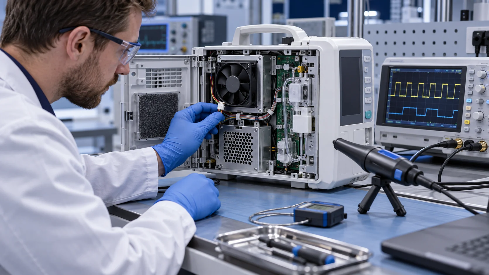
Record inlet air, outlet air, component temperatures, fan command, actual RPM, current and room sound on the same time axis. Repeat the test with the intended filter, cover, cable arrangement and cleaning state. Removing the cover or using an open bench fan can hide the pressure and recirculation effects that appear in the released console.
A First Heat-Loss and Airflow Estimate
A simple calculation turns electrical loss into an initial airflow target, then the installed pressure test shows whether the candidate can deliver it.
Consider an illustrative imaging console with 180 W of heat from the processor, power supply, display electronics and auxiliary circuits during a high-processing scan. If the design allows a 12 K average air rise, Q = P/(rho x cp x delta T). Using an air heat-capacity estimate of 1,200 J/(m3 K), Q = 180/(1,200 x 12) = 0.0125 m3/s, or approximately 26.5 CFM.
This is a screening target, not a guarantee. A local processor or power supply may need a lower temperature rise, and the console may have a filter, acoustic baffle, cable bundle and narrow exhaust. If the installed path requires 75 Pa at 26.5 CFM, the fan must deliver the flow at 75 Pa. A free-air CFM number alone cannot prove that the scan-state component temperature will be acceptable.
If a filter loads and adds another 35 Pa, the system curve changes. The control may increase fan speed, but the resulting sound spectrum and power must be checked in the room. If the fan reaches maximum command before the component limit is met, the design needs more pressure headroom, a better filter path, a local blower or a different thermal architecture.
| Input | Example | Use in the review |
|---|---|---|
| High-processing heat | 180 W estimate | Defines the active-scan state |
| Allowed average rise | 12 K | Screens about 26.5 CFM |
| Clean installed pressure | 75 Pa | Sets the initial P-Q duty |
| Filter drift | +35 Pa estimate | Checks speed and noise headroom |
| Acceptance evidence | temperature + spectrum + feedback | Releases the complete assembly, not just the fan |
Animated Model: Standby, Active Scan and Loaded Filter
The same console can move from a quiet stable state to a high-temperature, high-pressure state as processing and filter loading change.
In standby, sparse blue particles represent the minimum stable airflow that keeps the electronics ready without creating unnecessary sound. During active scanning, amber particles show the larger heat load and the controller may move to a higher verified state. With a loaded filter, red restriction markers show why the same RPM no longer proves the same flow.
The animated schematic below is qualitative. It is not a CFD result, an IEC limit or a product performance curve. It is designed to help the design team define the actual test sequence: clean console, active scan, loaded filter, acoustic measurement and recovery after the load drops.
A useful validation also checks the transition. A speed ramp that is thermally safe can still create an objectionable tonal event. A controller that reduces speed immediately after a scan may leave the heat sink warm and the console interior above its intended standby condition. Use hysteresis and a defined recovery time, then verify the room sound and component temperatures.

Noise Is a Spectrum and Installation Problem
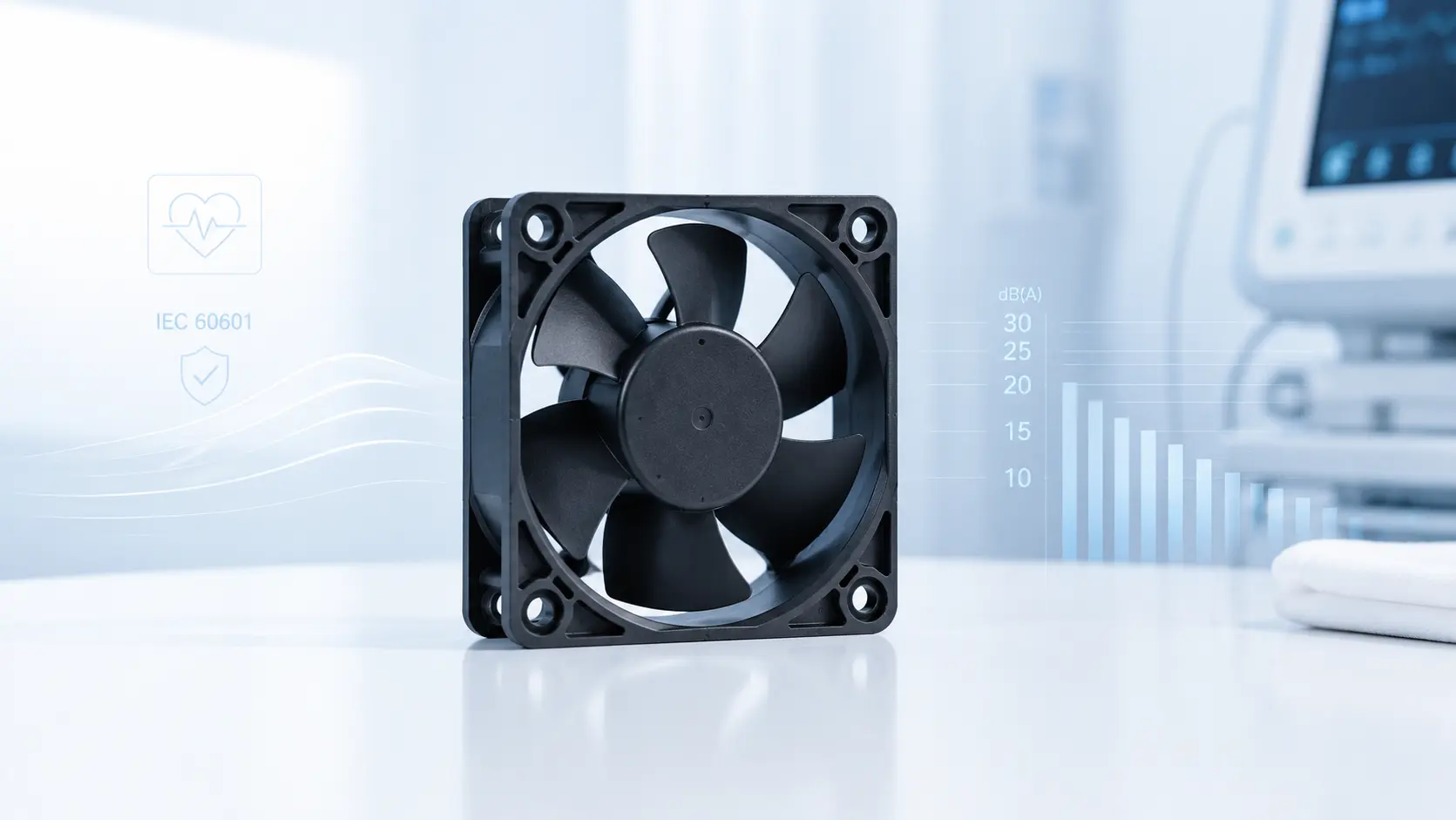
A medical console fan is heard by the patient and operator, so the design must control tonal peaks, vibration and speed transitions as well as average sound pressure.
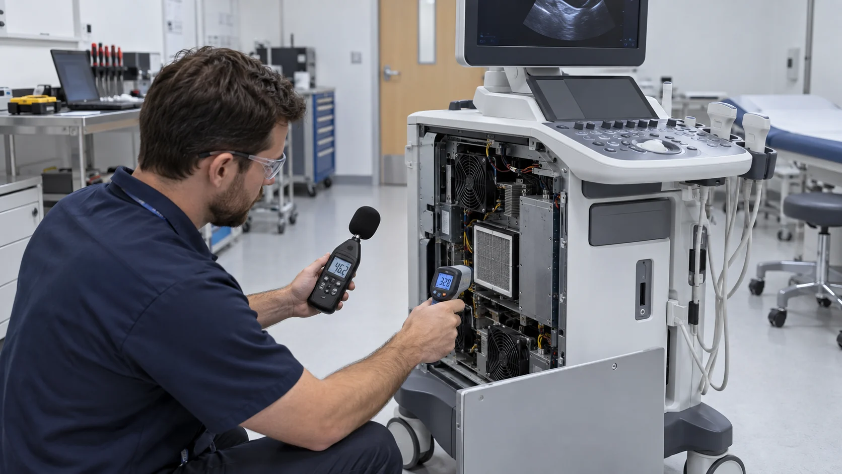
Measure at the clinical listening position and at the operator position, with the console in its normal orientation. Record startup, steady standby, active scan, maximum cooling and recovery. Include the transducer or accessory configuration that produces the intended processing load. The same fan can sound different after it is mounted behind a panel, grille or acoustic baffle.
Look at narrowband content as well as A-weighted sound pressure. Blade-pass frequency, motor commutation and panel resonance can create a tonal peak that is more noticeable than a modest broadband increase. Check whether a PWM strategy, speed range or mounting gasket moves the tone into a more objectionable band.
Avoid solving sound by commanding too little airflow. A better sequence is to reduce pressure losses, improve distribution, select a fan with useful pressure headroom, isolate vibration and then tune the control curve. The final acceptance should state where the measurement was made, which mode was active and what thermal condition was reached.
Filters, Cleanability and Clinical Airflow Boundaries
A filter protects electronics, but it also adds pressure, creates a cleaning task and can change airflow after repeated clinical use.
The inlet path may encounter dust, lint, cleaning residue and fibres from the clinical environment. The filter should be removable or serviceable according to the equipment procedure, and the design should make it difficult to reinstall incorrectly. A filter that is easy to access but poorly sealed can create a bypass path that sends unfiltered air to the fan or heat sink.
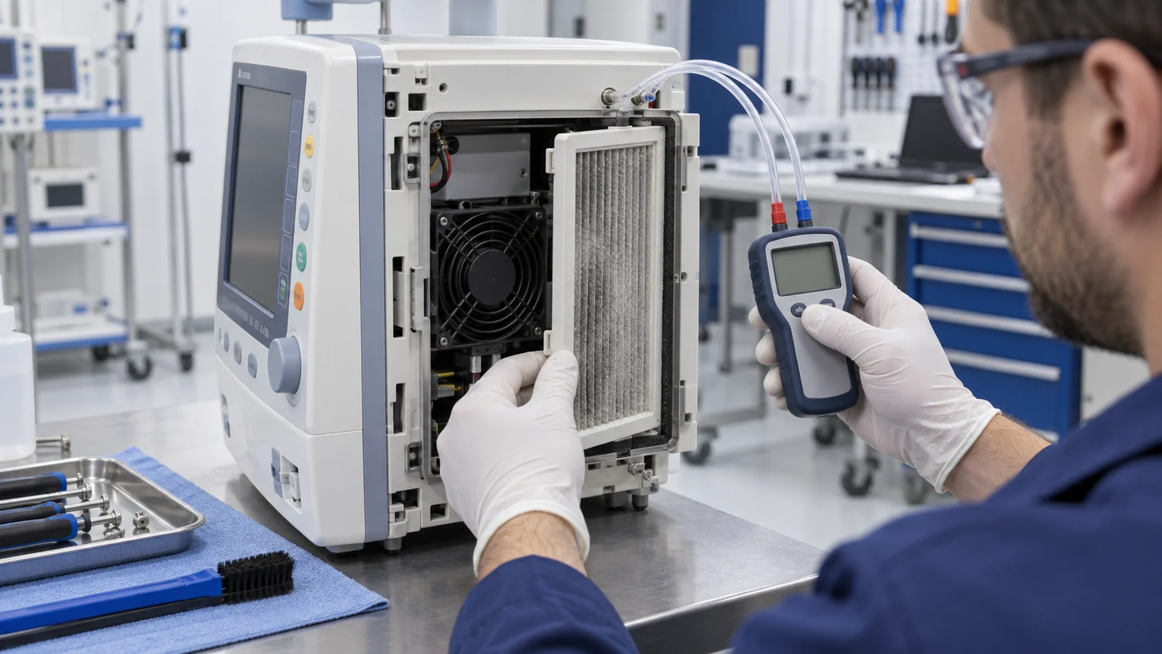
Test clean and service-limit conditions. Record differential pressure, airflow or a validated proxy, fan current, component temperature and room sound. The service threshold should be set before the fan reaches its maximum command or the scan-state thermal limit. If the product relies on a user cleaning the filter, validate the cleaning method and the effect of repeated removal on gasket compression.
Clinical cleanability is not the same as medical sterilization. The fan supplier can provide construction and materials information, but the equipment owner must define approved disinfectants, wipe access, ingress protection and the cleaning validation boundary. Do not claim that a fan's material or IP label alone makes the complete console clinically cleanable.
| Check | Record | Pass condition |
|---|---|---|
| Filter fit | seal, orientation and bypass path | air reaches the intended thermal zone |
| Clean condition | pressure, flow, temperature and sound | active scan meets all limits |
| Service condition | pressure rise and fan command | alarm occurs before thermal derating |
| Cleaning cycle | access, gasket and material compatibility | repeatable service without damage |
| Cover installed | distribution and recirculation | released enclosure, not open bench, passes |
EMC, Feedback and Single-Fault Response
Medical-device fan validation must include the electrical interface and the response to a fan or sensor fault, not only airflow and noise.
The fan's motor commutation, PWM input, FG output, cable routing and connector can interact with sensitive imaging or patient-monitoring electronics. Test the fan on the real harness and controller, including supply ripple, cable length, grounding and any shielding or filtering used in the console. A quiet fan that introduces a false alarm or imaging artifact is not a successful replacement.
Define what the equipment does when the fan is disconnected, locked, slow, intermittently connected or reporting an implausible FG signal. The response may be an alarm, controlled reduction of processing, service mode or shutdown depending on the device risk analysis. The fan supplier can support the signal behavior and sample evidence; the equipment owner defines the essential-performance response.
IEC 60601-1 is concerned with basic safety and essential performance of medical electrical equipment. A fan change should therefore be assessed for its effect on the device's risk controls and thermal boundaries. It is not enough to say that the replacement has the same voltage and frame size.
Long Scans, Recovery and Service-Life Evidence
A console can pass a short temperature test and still develop a problem during a long scan or repeated patient sessions.
Run the intended maximum processing condition for long enough to reach the limiting thermal state, then observe recovery after the load ends. Record component temperature, fan speed, sound spectrum and supply current over time. If the console is used repeatedly, include repeated scan blocks with the realistic idle interval rather than one isolated soak.
Bearing life should be considered against temperature, speed, orientation and duty cycle. A fan that runs slowly most of the time but repeatedly accelerates can see a different mechanical and acoustic duty from a constant-speed fan. If the fan is mounted vertically or in a constrained direction, confirm that the selected bearing construction and lubrication assumptions match the intended service life.
The release record should also state how a field technician detects degradation. FG trend, current, noise, pressure or temperature can provide evidence before a complete fan stop. Predictive monitoring belongs to the device owner, but a custom fan can expose the interface and stable signal behavior needed for that plan.
An Anonymized Ultrasound-Console Validation Example
A useful medical-device case connects a room-noise complaint to the pressure, filter and thermal data inside the console.
In an anonymized ultrasound-console development, operators reported that fan noise became more noticeable after several hours of scanning. The fan still met its nominal RPM, and the average sound level had not changed dramatically. A longer test showed a tonal peak during the transition from standby to active scanning, together with rising filter pressure and a higher console inlet temperature after the rear cover warmed.
The engineering team measured the fan at the populated console with the intended filter and cable routing. A custom sample with a revised pressure-flow point and a smoother low-speed transition was compared with the original at the same voltage and connector interface. The team recorded thermal recovery, sound spectrum at the operator position, FG behavior and the effect of the cleaning state.
The customer then revised the airflow restriction and control hysteresis instead of simply lowering the maximum speed. The final record separated the fan's contribution from the console's panel resonance and filter service condition. This is an anonymized engineering scenario, not a named customer result or a medical certification claim. The transferable lesson is that clinical acoustics and thermal reliability need the same installed test.
How MEGA Tech Supports Medical-Equipment Fan Development
MEGA Tech helps medical-equipment teams develop a fan interface that can be measured on the real console before production release.
We can review custom DC or EC axial fans, compact centrifugal blowers and fan modules for ultrasound consoles, imaging electronics, patient monitors, power supplies and diagnostic workstations. The review can include pressure-flow behavior, 12/24/48 V operation, PWM or voltage control, FG/RD feedback, startup, bearing selection, acoustic target, connector position, cable exit, filter pressure and sample validation on the customer's populated assembly.
For a first review, send heat loss by clinical state, target airflow at static pressure, fan envelope, voltage tolerance, control interface, connector, noise and tonal target, filter condition, cleaning procedure, EMC constraints, vibration environment, life assumption and quantity. A current fan part number helps replacement work, but same dimensions, voltage or RPM alone do not prove equivalent thermal, acoustic or EMC behavior.
Our boundary is clear: MEGA Tech does not certify the complete medical device, IEC 60601 risk file, EMC report, cleaning validation, clinical performance or regulatory submission. We support the fan and air-side interface, provide samples and help the equipment team validate the installed thermal, acoustic, feedback and fault behavior.
Recommended Fan Starting Points
These catalogue series may be suitable starting points for this application. Final selection depends on the installed airflow, static pressure, voltage, noise target and operating environment.
Request a sample for validation on your equipment.
Engineer FAQ: Medical Console Fan Validation
Use these questions during a design review, supplier comparison or service investigation.
Q: Is the quietest fan automatically the best medical fan? A: No. It must meet the installed pressure, component temperature, EMC, feedback, service and fault requirements at the same time.
Q: Does a lower RPM prove lower noise? A: No. Installation, blade-pass tone, panel resonance and airflow restriction can dominate the perceived result.
Q: Can I use the same fan for standby and maximum scan? A: Possibly, but the control range, pressure margin, startup, recovery and acoustic transition must be validated on the console.
Q: Does an IP-rated fan make the console cleanable? A: No. The equipment owner must validate filter access, seals, approved cleaning agents, wipe access and the complete enclosure.
Q: What should happen after a fan fault? A: The device owner must define the safe response through its risk and essential-performance analysis; the fan supplier supports feedback and sample evidence.
Q: What should I send MEGA Tech? A: Heat by mode, airflow at pressure, fan envelope, voltage, PWM/FG/RD, acoustic target, filter, cleaning, EMC, life and quantity.
Q: Can MEGA Tech replace a branded medical fan? A: We can evaluate a cost-competitive replacement, but equivalence must be proven at the installed thermal, acoustic, EMC, feedback and environmental conditions.
Q: Can the fan supplier certify the medical device? A: No. The device manufacturer owns the complete safety, EMC, clinical and regulatory qualification.
Medical Console Cooling Design Review Checklist
Record these decisions before releasing the fan, filter, control curve or service procedure.
- What is the limiting component and what are the startup, scan, standby and recovery heat states?
- What airflow and static pressure are required at clean and service-limit filter conditions?
- Where are inlet, outlet, component, panel and room sound measurements taken?
- Has the released cover, cable routing and filter been tested instead of an open bench setup?
- Were tonal noise, speed hunting, vibration and panel resonance checked?
- Were PWM, minimum start, FG/RD, voltage tolerance and EMC interactions validated?
- What happens after a locked rotor, missing feedback, blocked filter or sensor fault?
- Can the fan and filter be serviced without compromising the device's cleaning and safety boundary?
- Were long active-use scans and repeated patient sessions included?
- Which results are measured, which are estimates and which belong to the complete medical-device qualification?