The cooling fan answers to two bosses
In a medical device the same fan must be quiet enough to be forgotten and reliable enough to never stop. Those two constraints usually come from different standards, and both are non-negotiable.
Industrial cabinets solve one cooling question: move the heat out. Medical equipment solves two at once. The fan has to hold acoustic targets for a patient, a family and a clinical team in the same room with it, and it has to keep some of the most failure-sensitive electronics in a safe temperature band while a clinician depends on it mid-procedure.
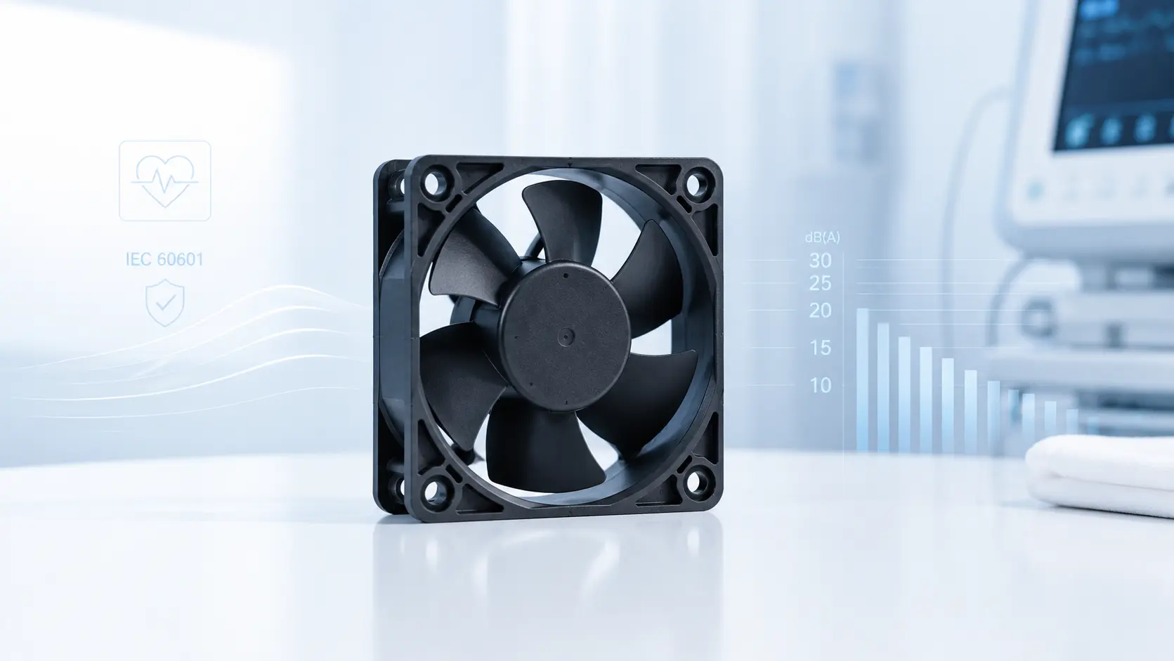
Neither headline is a marketing soft number. WHO guidance addresses noise exposure in health-care settings, while the finished medical electrical equipment must meet the applicable IEC 60601 safety requirements. The fan supplier contributes component data and verification evidence; the device manufacturer remains responsible for the complete equipment, intended use and regulatory submission.
The regulatory weight is real and worth naming early: a cooling fan is a component, not a medical device by itself. But changing it can affect the device's thermal, acoustic, EMC and risk evidence. FDA guidance says device modifications should be evaluated with a risk-based assessment, including whether safety or effectiveness is significantly affected. A fan picked late, then swapped, can mean reopening the affected verification and risk records.
This is why the fan is rarely the first component a medical design team wants to specify — and why it is often the one that creates the most rework when it is picked late. Design the airflow path from the acoustic and safety target down, not from a free-air CFM number up.
Quiet is a safety feature, not a comfort extra
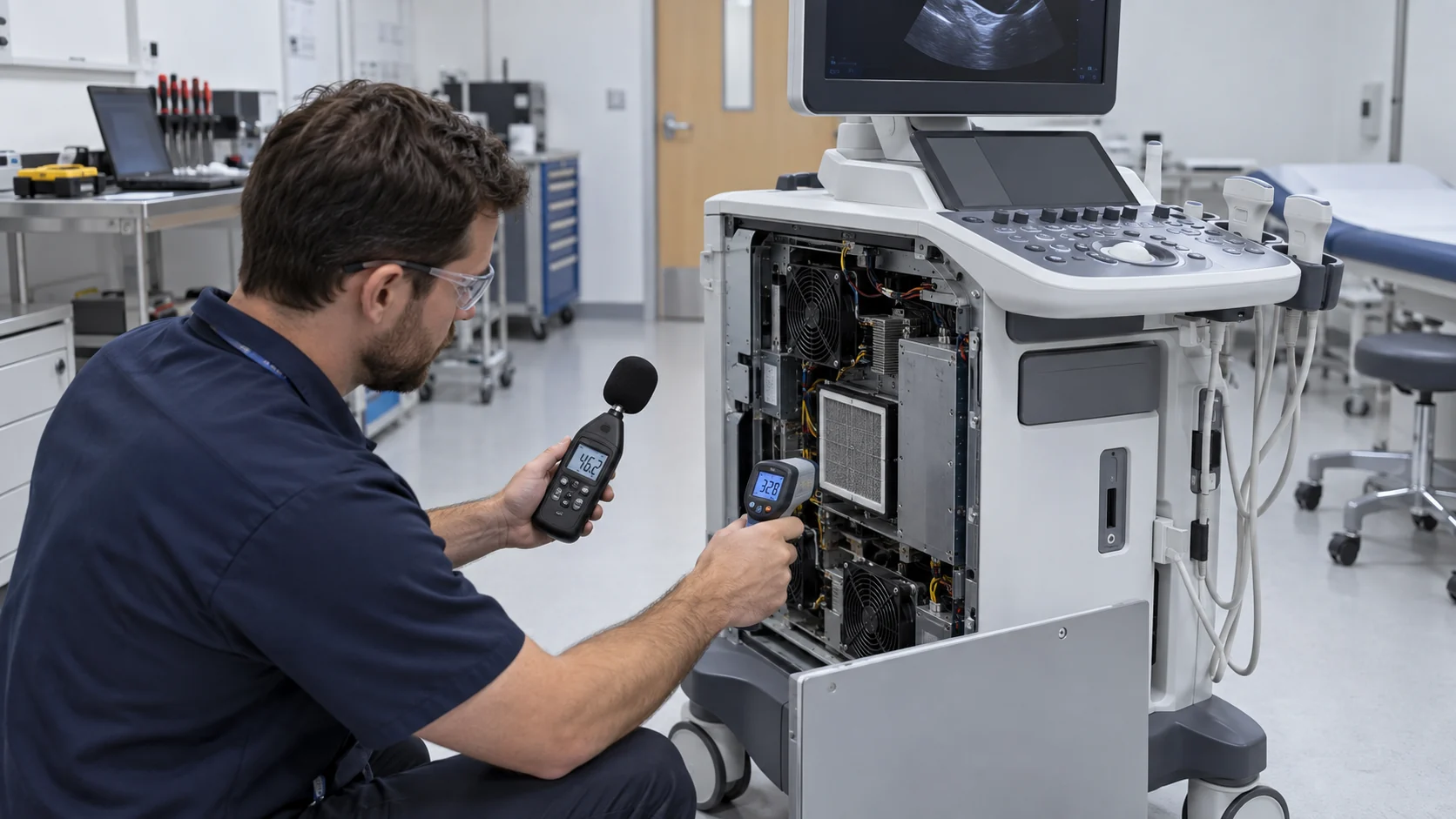
Hospital acoustic guidance is explicit about the environment, not a universal fan specification. WHO says noise exposure in many rooms where patients are treated or observed should not exceed 35 dB, while nighttime and sleep-sensitive settings can require lower levels. Translate that room-level reference into an installed-device noise budget after accounting for the existing room background, measurement distance, enclosure and other equipment.
Two acoustic details separate an experienced medical acoustic report from a rushed one. First, tonal noise: a pure blade-passing tone or PWM switching whine can be more disturbing than broadband noise at the same overall level, so specify spectral data, not just an overall SPL figure. Second, PWM audibility: a switching frequency above the audible band may help, but it is not a guarantee because motor electronics, chassis resonance and control harmonics can reintroduce tones. Verify the complete device with a spectral acoustic test and use a soft-start profile so the device does not announce power-up with a tonal thump. Where the test plan needs sound power, use the selected ISO 3744 method rather than estimating it from a catalogue SPL.
Noise is also clinical interference. In an operating room, staff need to talk and listen for subtle cues; a whining fan masks them. Near a patient at night, even a light fan hum becomes a sleep disruption that slows recovery. And a fan vibrating through the chassis can couple into sensitive analog or optical subsystems — a fault that shows up as low-level measurement instability far from the fan itself. Line-frequency vibration matters here: AC fans carry 50/60 Hz ripple, which imaging platforms are especially sensitive to.
Fewer decibels is not a taste preference. It is an installed-device requirement that should be recorded in the acoustic verification plan and measured with a repeatable method, not by ear.
IEC 60601 turns cooling into a safety question
The safety standard for medical electrical equipment applies a concept most electronics designers meet rarely in industrial work: a cooling failure can be a safety failure mode. IEC 60601-1 includes requirements related to accessible temperatures, but the applicable limit depends on the edition, contact condition, duration and equipment context; use the device manufacturer's compliance interpretation rather than copying one number into a fan specification.
The consequence is direct. If a fan failure could cause an accessible surface, patient connection or essential-performance function to exceed its limit, the failure mode must be analysed and controlled in the device's risk-management file under ISO 14971. That is why a fan in a medical device is not a commodity assembly-line part — its failure behaviour is part of the complete device's documented safety case.
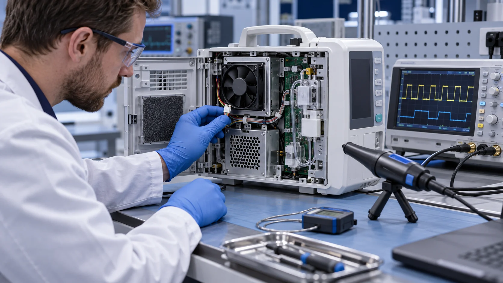
Materials and electrics inherit the same discipline. Frame and impeller flammability, electrical insulation, creepage, clearance and leakage-current requirements must be specified for the actual device architecture rather than assumed from a catalogue label. The standard family extends into EMC: if a fan platform is part of medical electrical equipment or its system, the motor drive, PWM controller and filtering need to be evaluated within the applicable evidence, including IEC 60601-1-2 where it applies. A noisy PWM driver can be as much of a compliance problem as the fan's airborne noise.
One more layer often surprises industrial engineers: infection control. Devices that move air near patients — ventilators, air sterilisers, filtration carts — may need sealed or easily-cleanable fan housings, low-VOC materials, and resistance to the disinfectant agents the cleaning protocol uses. The fan becomes a surface the hospital touches daily.
The right speed is the lowest one that works
Because a fan at reduced speed is usually quieter, the cheapest acoustic improvement in a medical device is not always a quieter fan — it can be a lower operating speed. The exact reduction depends on fan geometry, control method, enclosure and measurement method, so treat any speed-to-noise figure as a model-specific estimate and verify it in the assembled device.
The practical recipe is to run the fan at the minimum speed that still satisfies the thermal requirement for the worst ambient and load, and to modulate it with temperature feedback via PWM: a thermistor at the heat source feeds a controller that trims speed continuously — closed-loop stability rather than on/off cycling, which is exactly what temperature-sensitive subsystems such as imaging optics want.
Airflow design should support this by removing pressure drop rather than fighting it. Smooth ducts, radiused inlets, generous inlet area and vibration-isolated mounts each return real acoustic margin; so does avoiding a high system impedance that forces a small fan to spin faster than intended. The compound effect is easy to test: compare the original and revised airflow path at the same heat load, then record sound pressure, tonal peaks, component temperature and fan speed. A larger, slower fan may create acoustic and bearing-life margin, but the improvement belongs to the tested assembly rather than to the frame size alone.
Size and speed interact with the acoustic report in a simple direction: for the same airflow, a bigger slow fan generates less blade-passing noise than a small fast one. Where the enclosure allows the diameter, take it.
| Strategy | What it changes | Net effect |
|---|---|---|
| PWM speed control with temperature feedback | Runs at minimum speed that meets thermal need | Can reduce noise at light load; quantify the installed result |
| Larger, lower-RPM fan | More airflow at lower blade-passing frequency | Quieter for equal cooling |
| Low system impedance (smooth ducts, vent area) | Less pressure drop, fan stays slower | Recovers acoustic margin immediately |
| PWM above 20 kHz / spread spectrum | Switching energy leaves the audible band | Removes coil-whine tones from the report |
The failure that alarms nobody: slow airflow decay
The dangerous failure in a medical fan is not the stall you hear — it is the silent slide from 'healthy' to 'barely adequate' while the tachometer still reads in range.
Fan failures come in two classes. Overt failures — a stopped rotor, a dead drive, a broken lead — are loud in both senses: the device alarms, the session stops, and the cost is downtime. Hidden failures are the medical-grade problem: bearings wear and lubricant degrades, airflow decays slowly, noise creeps up, and the tachometer signal stays within its allowed window while the actual cooling capacity is no longer sufficient. The device keeps running, no alarm fires, and the core electronics spend months under chronic heat stress — a lifetime-shortening failure mode that is difficult to trace after the fact.
Two engineering habits counter it. First, respect the duty profile: PWM strategies that cycle fans on and off aggressively, or run them so slow that bearing lubrication is marginal, shorten real service life even though the noise numbers look better — life under a PWM duty cycle should be validated, not assumed from the catalogue curve. Second, validate like a medical device, not a consumer one: high-temperature continuous burn-in, PWM control simulated as it will actually run, airflow-decay trend monitoring over life, and noise evaluated over time rather than only at handover.
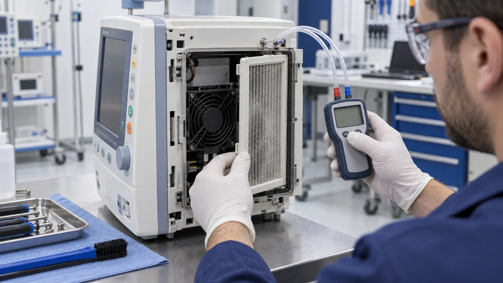
The hospital environment makes this worse than the datasheet assumes. A ward is not a clean room: dust loads filters, disinfectant gases and humidity attack bearings and windings, and cleaning agents reach the fan during daily wipes. Environmental exposure testing — cleaning agents, humidity cycling, worst-case thermal load — belongs in the verification plan.
Monitoring can shorten the warning window: current, speed, airflow or vibration trends can flag a fan that is degrading before a complete stop. The lead time is application- and algorithm-specific, so use trend thresholds validated on the chosen fan and duty cycle rather than promising a fixed number of hours or days. For critical equipment, that monitoring can convert fan maintenance from reactive replacement to a scheduled-service item.
Reliability has to be designed as a layer, not hoped for
In a patient-care device, unplanned downtime is not an inconvenience — it is a clinical risk. The design should treat fan reliability as a system property: redundancy, feedback, and traceability.
Redundancy gives the device a landing gear. Running fans in N+1 can preserve the required temperature margin after one fan stops, but only if the post-failure airflow, noise and power conditions are validated. A fault signal (tachometer or alarm output) tells the device to alert staff rather than overheat slowly. For ventilators and life-sustaining systems this alarm path is expected, often routed to the nursing station — and an underspeed alarm matters more than a stopped-fan alarm, because underspeed is what the slow-decay failure actually looks like.
Device class sets the numbers. Life-support, imaging, bedside and portable products have different essential-performance, acoustic, vibration and service requirements; there is no single fan MTBF, bearing or dBA value that fits them all. Set the requirement from the device risk analysis, then ask the supplier to state the test condition behind its L10, acoustic, vibration and temperature data. For critical functions, combine the selected fan's feedback with an appropriate redundancy or safe-state strategy rather than treating a catalogue MTBF as a system guarantee.
Bearing life itself deserves an engineering treatment, not a catalogue glance. Life is quoted as L10 — the point where 90% of a population survives — and it falls steeply with temperature, so the L10 figure must be read at the fan's real internal ambient, not room temperature. Verification should pair the calculation with run-in testing at worst-case thermal load, plus vibration and shock tests matching transport and daily-use handling. Cleaning-agent exposure, humidity cycling and burn-in results belong in the same IEC 60601 technical-file evidence pack.
The supply chain is part of the reliability story too. Medical products can stay in production for ten or more years, so the supplier should commit to long-term availability, provide lot traceability for materials like bearings, and issue Material Change Notifications before altering design or process. Substituting a fan model mid-production is a change that needs re-risk-assessment under the quality system — not an equivalent-part swap on a cost spreadsheet. Ask for these agreements up front; they are part of the ISO 13485 quality-system relationship, not a post-contract courtesy.
Choosing the quiet fan for the device class
The right fan tracks the device's noise budget and power level more than any single size. Our 48 V DC axial line covers the range with models selected for low noise at practical operating points.
For respiratory and patient-facing gear where every decibel near the pillow matters, the 72–92 mm class with the lowest verified installed noise is a practical starting point. Where a device can spare diameter, a 120–140 mm low-speed axial may move more air at a lower operating speed and create acoustic margin; confirm the result in the final enclosure. Handheld and portable products that cannot afford the thickness may push toward micro-blowers instead — centrifugal delivery in a compact envelope — trading peak airflow for static pressure on a single hot component.
- MG9225L48X — 92×92×25 mm, 48 V, about 31.9 CFM at 2.0 mmH2O, 27.5 dBA: an ultra-low-noise choice for bedside and ventilator-class equipment.
- MG8025L48X — 80×80×25 mm, 48 V, about 19.2 CFM at 1.8 mmH2O, 25.0 dBA: the quietest in the small class for patient and portable devices.
- MG12030L48X — 120×120×30 mm, 48 V, about 64.2 CFM at 1.8 mmH2O, 30.5 dBA: higher airflow for imaging power supplies while staying low-noise.
- Confirm PWM, tachometer/fault feedback and the operating-temperature range with our engineering team so the operating point and the IEC 60601 documentation both line up.
Develop the fan with the medical device
Medical equipment needs a cooling fan that fits the device, the acoustic report and the long-term supply plan at the same time.
MEGA Tech can support medical-equipment teams from the first cooling requirement. We review the available space, heat load, airflow path, pressure loss, acoustic target, voltage, control method, mounting orientation, cleaning environment and expected service life before recommending a fan platform.
If a catalogue model is close but not right, we can develop a customized sample around the device: lower-noise operating point, airflow and pressure target, PWM response, FG or fault feedback, bearing configuration, connector, cable length, material and mounting details. The customer can evaluate the production-representative sample in the actual enclosure before committing to volume production.
For startups and smaller medical-equipment programs, this sample-first approach helps control development cost while the product is still being refined. We can adjust the cooling solution with the engineering team, document the confirmed configuration and carry the approved fan into reliable, repeatable production. Medical-device certification remains the responsibility of the complete device and its regulatory process, while the fan supplier supports the component data and verification evidence needed by that process.
- Define the installed acoustic, thermal and reliability requirements before choosing a model.
- Customize the fan around the device envelope, control interface and operating environment.
- Validate noise, airflow, temperature, vibration and fault response in the real enclosure.
- Move the approved sample configuration into stable long-term production.
Engineer FAQ: Medical Fan Noise and IEC 60601 Validation
A medical fan must satisfy the installed acoustic and thermal safety case of the complete device, not just a catalogue dBA value.
Q: Is 35 dB a universal medical fan requirement? A: No. It is a healthcare-environment reference used to frame the acoustic problem. The device team must set an installed target for the patient, operator or bystander position, accounting for background noise, enclosure, duty cycle and the applicable clinical environment.
Q: Does IEC 60601 certify the cooling fan itself? A: No. IEC 60601-1 addresses basic safety and essential performance of medical electrical equipment. A fan is a component whose change can affect thermal, acoustic, EMC and risk evidence; the complete device manufacturer remains responsible for the applicable compliance assessment.
Q: Should medical fan noise be compared only by dBA? A: No. State whether the result is sound pressure or sound power, where it was measured, at what airflow and pressure, and whether tonal peaks, PWM whine and structure-borne vibration were reviewed. ISO 7779, ISO 10302 or another applicable method should be selected for the equipment and test objective.
Q: Does lowering RPM always make a medical device safer and quieter? A: Lower speed can reduce noise, but only if the fan still meets the thermal requirement and the control remains stable. Validate minimum speed, startup, PWM duty, temperature feedback, acoustic spectrum, bearing conditions and component temperature at worst load and ambient.
Q: Can a tachometer prove that a medical fan is healthy? A: No. A worn or restricted fan can continue reporting speed while useful airflow falls. Establish a healthy baseline and combine speed or fault feedback with airflow or pressure, current, noise, vibration and device-temperature trends where the risk analysis requires it.
Q: Does N+1 remove the need for a fan fault alarm? A: No. Redundancy and alarm response solve different problems. Test the post-failure airflow, temperature, noise and power condition, and define how the device enters a safe state or alerts staff after a stopped or underspeed fan.
Q: What should be checked when replacing a medical fan with another model? A: Re-check frame and mounting, airflow and pressure at the installed point, accessible temperatures, acoustic spectrum, vibration, EMC, material and cleaning-agent compatibility, fault behavior, service life and the device risk file. An apparently equivalent frame-size fan is not automatically equivalent evidence.
Q: What should a customized medical fan sample prove before production? A: Test the representative enclosure and controller at normal, peak and relevant transient duty. Record airflow, pressure, temperature, RPM, current, power, sound pressure or sound power, tonal and vibration components, PWM response, fault feedback, environmental exposure and long-duration behavior.
- Tie every numerical answer to voltage, speed, temperature, mounting and test condition.
- Separate catalogue maximums, engineering estimates and measured application results.
- Use the FAQ to define the next measurement or sample-validation step.
Final review checklist
Cooling in a medical device is a two-boss problem: the acoustic budget and the safety case. Verify both against the installed reality.
- Is there a numeric dBA target at the patient's operating distance — with spectral data — not just at full fan speed?
- Has PWM switching and any spread-spectrum strategy been checked for audible tones in the final enclosure, rather than assumed inaudible?
- Does the fan run at the minimum speed that still meets thermal need at worst ambient and load — with life validated under the real PWM duty cycle?
- Has the surface-temperature limit been checked against what happens if the fan stops, and logged in the ISO 14971 risk file?
- Is there N+1 redundancy or a fault alarm — including an underspeed alarm, not only a stopped-fan alarm — for critical or life-sustaining devices?
- Has the fan been validated against the hospital environment: dust, disinfectants, humidity, cleaning agents?
- Are PWM, tachometer/fault feedback and the operating-temperature range confirmed with the supplier?
- Has the supplier committed to long-term supply, lot traceability and Material Change Notification?