A Medical Fan Is Part of the Essential-Performance Chain
A cooling fan can affect temperature, noise, alarms, EMC and service reliability, so its replacement cannot be approved by airflow alone.
Medical equipment often has a narrow operating envelope. A fan may cool a power converter, patient-monitoring electronics, imaging subsystem, pump controller or air path, while the same equipment must maintain predictable alarms and essential performance in the presence of electrical disturbances. A fan with the right pressure and frame can still create a false tachometer alarm, inject switching noise, or fail to cool the protected component after a warm restart.
IEC 60601-1-2 addresses electromagnetic disturbances, emissions and essential performance at the medical equipment or system level. The fan supplier can provide electrical behaviour, operating-point data and sample evidence, but the device manufacturer owns the risk analysis, EMC test plan, alarm response and final compliance decision. This boundary should be written into the fan specification rather than assumed after the fan is installed.
This article gives medical-equipment engineers and purchasers a practical fan-side validation method. The examples are illustrative planning values, not medical claims, IEC test results or MEGA product ratings. Use the applicable particular standard, risk file, device architecture and accredited test plan for the final release.
Define the Medical Device Cooling Contract
Describe the protected function, operating states and safe response before choosing a fan.
Start with the protected function: does the fan preserve a controller temperature, maintain an air-delivery rate, prevent a power-stage derating event, or protect a sensor and patient-facing function from drift? Then define normal, warm, standby, transport, cleaning and fault states. A medical device that is quiet and cool in normal operation may need a different fan duty after a door is closed, a filter loads or a power module reaches steady state.
Write the fan-side inputs and outputs. Inputs can include supply voltage, PWM or voltage command, ambient temperature, filter condition and device mode. Outputs should include RPM or feedback, current, temperature at the protected component, airflow or pressure proxy, acoustic condition and the device alarm or derating response. This creates a traceable link from the fan to the risk-control measure without claiming that the fan alone is a safety control.
Include environmental and cleaning boundaries early. Dust, disinfectant vapour, lint, condensation, elevated ambient temperature and repeated power cycles can alter bearing friction, connector condition and filter resistance. The final medical device may have a cleaning and service process that differs from a general industrial product. The fan sample should be evaluated inside that declared boundary rather than against a generic catalogue life number.
| Contract | Record | Why it matters |
|---|---|---|
| Thermal | protected component, normal/worst temperature and margin | links fan duty to essential performance |
| Electrical | voltage, PWM, current, FG/RD, startup and restart | prevents false alarm and interface mismatch |
| EMC | installed cable, driver and system test boundary | fan switching can change the system evidence |
| Acoustic | measurement position, mode and limit | clinical use may care about tonal noise, not only average dB(A) |
| Service | cleaning, filter, duty, life and replacement method | keeps maintenance assumptions reproducible |
Validate Alarm Logic with Real Fan States
A fan alarm is useful only when the device can distinguish no power, no rotation, low airflow and a sensor fault.
Test at least five controlled states: normal rotation, command with no supply, supply with locked rotor under a safe procedure, missing or invalid feedback, and a restricted air path with the rotor still spinning. The exact test method belongs to the device risk plan. The goal is to show which condition the controller detects and what the device does next: alarm, derate, controlled stop, service message or continued operation with a documented margin.
A planning example is a fan commanded at 70% PWM that reports 4,000 RPM while the protected component remains above its limit because a filter or duct is blocked. The alarm logic sees rotation but not the lost airflow. Conversely, a replacement fan may deliver the required airflow while its FG pulse count differs from the controller's expected range, causing a nuisance alarm. Both cases show why RPM is evidence, not the whole cooling contract.
Record alarm delay, hysteresis, recovery and reset behaviour. If a fan restarts after a transient supply dip, does the device wait for stable feedback before clearing the alarm? If the fan stalls during a critical phase, does the device preserve the patient-facing function, enter a safe state or require service? These are system decisions, but the fan sample must reproduce the electrical and mechanical conditions used in the test.
Keep the safety language precise. A fan supplier can verify the sample's startup, current, feedback, pressure and temperature response; the medical device manufacturer must decide whether those results support the device's risk controls and essential-performance verification.

Treat EMC as an Installed-System Question
The motor, driver, cable and controller form one electrical interface inside the medical device.
A DC fan can introduce conducted or radiated disturbances through its driver switching, commutation, cable routing and return path. The result depends on the complete equipment layout: cable length, grounding, filtering, controller impedance, nearby sensor lines and the selected PWM strategy. A bench fan test with a short cable cannot replace the device-level EMC assessment.
IEC 60601-1-2:2014 with its 2020 amendment describes requirements and tests for electromagnetic disturbances and emissions for medical electrical equipment and systems. FDA guidance likewise treats EMC as part of the medical-device assessment. These references do not mean that every fan supplier must perform the entire medical-device test; they mean the fan interface and any mitigation must be included in the device manufacturer's evidence and risk management.
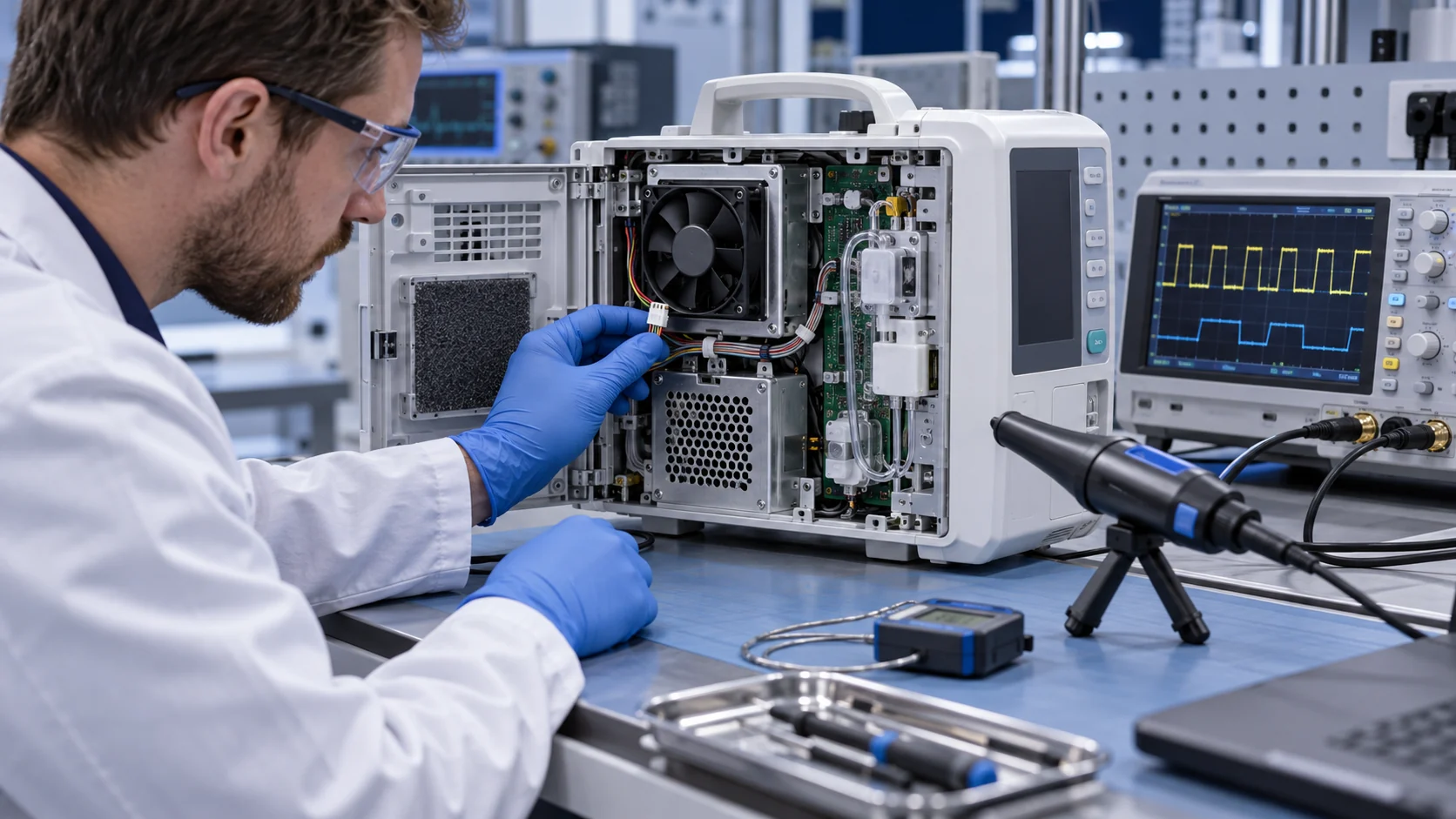
For fan-side engineering, record PWM frequency and edge behaviour, supply ripple, current transients, cable length, connector, shielding or filtering and feedback waveform. Test fan start, stop, speed changes and restricted conditions that can create different transients. If the replacement fan changes the driver or current profile, repeat the relevant system checks instead of assuming mechanical equivalence.
Do not promise ‘IEC 60601 compliant fan’ unless the exact claim, test boundary and certification evidence exist. A more accurate statement is that the fan sample was evaluated as part of a declared medical-equipment interface and the device maker must complete the applicable EMC and safety verification.
Use a Four-Pass Validation Plan
The fan sample should pass mechanical, electrical, thermal and system-response checks before the medical device design is frozen.
Pass one is mechanical: frame, guard, airflow direction, cable route, cleanability, mounting stress and clearance. Pass two is electrical: voltage, PWM or voltage control, startup, restart, current, FG/RD and connector retention. Pass three is thermal and acoustic: installed pressure or airflow, protected temperatures, warm ambient, filter state and the declared acoustic mode. Pass four is system response: alarm, EMC-sensitive operating states, device recovery and essential-performance criteria.
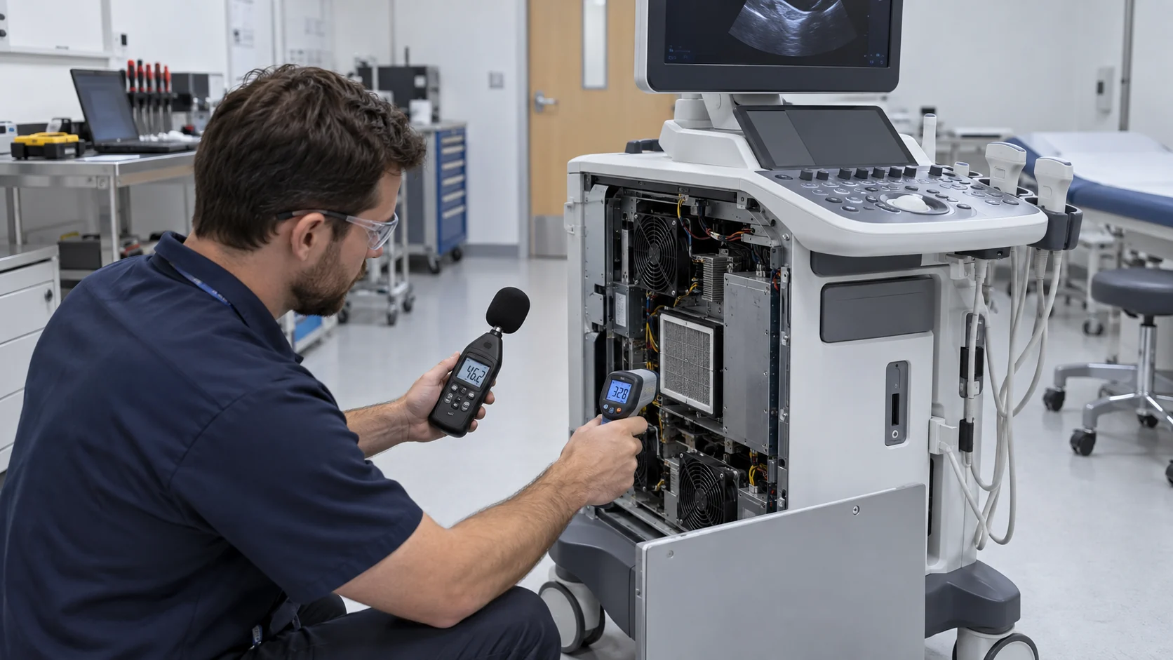
Use a reference fan and candidate fan in the same fixture where possible. Hold the measurement position and device state constant. Compare not only maximum airflow, but the installed point, command-to-RPM map, current transient, feedback timing, temperature margin and fault response. If the candidate needs a different firmware threshold or filter, that is a system revision, not a silent drop-in substitution.
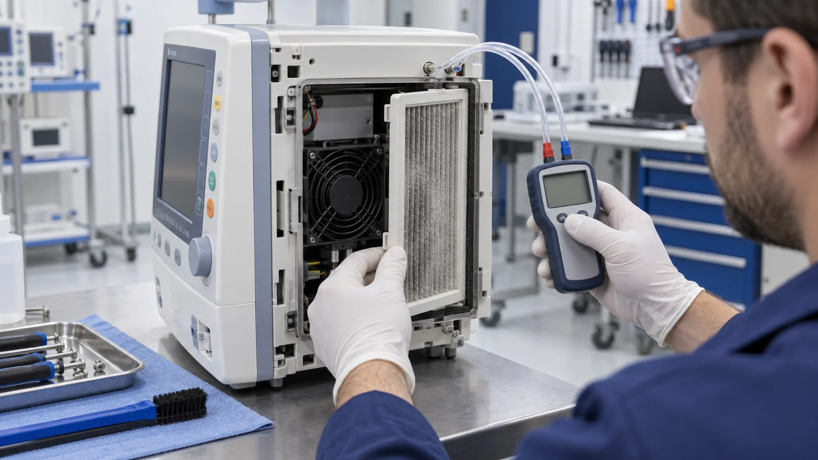
Include maintenance. WHO's medical-equipment maintenance guidance distinguishes performance inspections, safety inspections and preventive maintenance intended to reduce failure rates. For a fan assembly, that translates into a defined inspection interval, filter or inlet condition, cleaning method, replacement record and post-service functional check. A fan can be reliable and still fail the device if the maintenance state is undefined.
| Pass | Evidence | Release question |
|---|---|---|
| Mechanical | drawing, cable/guard inspection and cleaning check | can it be installed and serviced without a new hazard? |
| Electrical | waveforms, current, feedback and restart log | does the controller interpret the fan correctly? |
| Thermal/acoustic | installed pressure, temperatures and sound by mode | does it preserve the declared operating margin? |
| System | alarm, recovery, EMC-sensitive states and risk-file link | does the device remain inside essential performance? |
| Maintenance | inspection interval, service state and replacement record | can the result be reproduced after service? |
How MEGA Tech Can Support a Medical Fan Sample
MEGA Tech can support fan-side engineering evidence while keeping medical-device certification and risk ownership with the device manufacturer.
MEGA Tech develops custom DC axial fans and compact blowers for medical and laboratory equipment where airflow, static pressure, noise, temperature, control and reliability must be defined together. The review may include frame or thickness, connector and cable, PWM or voltage response, FG/RD feedback, bearing configuration, airflow direction, mounting detail, acoustic target, environmental boundary and replacement compatibility.
For a medical review, provide the device function, protected component, operating modes, available envelope, inlet and outlet path, required pressure or airflow, voltage and control interface, feedback expectation, ambient and cleaning conditions, acoustic limit, duty cycle, EMC-sensitive states, first-build quantity and applicable device acceptance plan. If replacing a known Sanyo Denki, SUNON, Delta, NMB or ebm-papst fan, include the installed working point and alarm behaviour rather than only the part number.
We can build a small first sample, compare it with the reference interface and provide fan-side measurements for the device team's verification. We do not issue medical-device certification, EMC certification or clinical claims. The device maker owns risk management, particular-standard assessment, essential-performance definition and final release.
Representative Replacement Review
An anonymous example shows why the fan, alarm and EMC review must be run as one controlled change.
Consider a compact clinical monitoring unit whose original 24 V fan had a three-wire speed signal. The device team wanted a lower-cost second source with the same frame and connector. On the bench, the candidate fan produced similar free-air flow and a lower average noise value. After installation, however, the device reported intermittent low-RPM alarms during warm restart and a nearby sensor showed a repeatable disturbance during the fan speed transition.
The review separated the conditions instead of rejecting the sample from one symptom. The team checked the connector pinout, pull-up voltage, pulses per revolution, startup current, PWM edge behaviour, cable route and the alarm delay. It then measured the protected electronics temperature through normal, warm, standby and restart states. The candidate's airflow was acceptable at the installed restriction, but its feedback map and current transient were not equivalent to the reference interface.
The sample was revised with the required feedback behaviour and the cable/driver interface was retested in the device fixture. The device manufacturer then repeated its applicable EMC and essential-performance checks. The result of this representative scenario is not a certification or a guaranteed improvement; it is the sequence that prevents a mechanically compatible fan from becoming a hidden alarm or EMC change.
For purchasing, the lesson is equally practical: request the test condition, sample revision and feedback definition with the quotation. For engineering, keep the fan-side measurements linked to the device risk file and release record. This makes a future supplier change traceable instead of forcing the team to rediscover the same fault in the field.
Recommended Fan Starting Points
These catalogue series may be suitable starting points for this application. Final selection depends on the installed airflow, static pressure, voltage, noise target and operating environment.
Request a sample for validation on your equipment.
Engineer FAQ: Medical Equipment Fan EMC and Alarms
Use these questions in a design review before approving a medical cooling fan or replacement.
Q: Does an IEC 60601-1-2 reference prove the fan is certified? A: No. The standard applies to the medical electrical equipment or system. The fan can contribute evidence, but the device manufacturer owns the applicable EMC and safety assessment.
Q: Is FG feedback enough to prove cooling? A: No. FG reports a defined rotational signal. Pair it with installed airflow or pressure, protected temperature and the device's alarm logic.
Q: Can a quieter fan be safer? A: Only if thermal margin, feedback, EMC behaviour and fault response remain acceptable. Acoustic improvement alone is not a medical-device release criterion.
Q: What should be tested after changing PWM frequency? A: Repeat relevant acoustic, current-transient, feedback, temperature and EMC-sensitive operating-state checks. The driver waveform and cable path may change the system result.
Q: What if the fan runs but the filter is blocked? A: A rotation alarm may not detect lost airflow. The device risk plan needs a validated proxy, pressure sensor, temperature response or maintenance control as appropriate.
Q: What can MEGA Tech customize? A: Frame, thickness, airflow direction, connector, cable, PWM, FG/RD, bearing, pressure/airflow duty and mounting details can be reviewed around the medical equipment requirement.
Questions for the Medical Fan Design Review
A short checklist keeps a fan substitution from becoming an undocumented safety or EMC change.
- Which protected function and essential-performance limit depend on this airflow path?
- What are the normal, warm, standby, cleaning, service and fault states?
- What does the controller expect for voltage, PWM, FG/RD, startup and alarm timing?
- How is missing rotation distinguished from blocked airflow or an overtemperature condition?
- Which cable, driver, filtering and grounding details are part of the EMC test setup?
- What installed pressure, airflow, temperature and sound values define acceptance?
- What does the device do during fan stall, feedback loss, supply dip and recovery?
- Which claims belong to the fan supplier and which require device-level or accredited testing?
- How will preventive maintenance, cleaning and post-service verification be documented?
- Has the candidate sample been tested on the actual medical equipment interface before release?