A Clean Filter Is Not the Worst-Case Design Point
Medical equipment cooling can degrade slowly: the fan still spins, but filter resistance and inlet temperature move the system away from its validated operating point.
Fans inside patient monitors, laboratory analyzers, infusion equipment, imaging accessories and power-control cabinets often work behind a grille, pre-filter or dust barrier. The device may pass its factory test with a clean path and then run for months in a different service condition. Dust loading, lint, cleaning residue, a mis-seated filter or a blocked inlet can add pressure drop without immediately creating a fan alarm.
The engineering question is not only whether the fan reaches its nominal RPM. It is whether the installed airflow remains sufficient at the filter state and ambient condition that the device risk assessment declares. A fan can rotate normally while the protected electronics warm, a power stage derates or a temperature alarm arrives late. This is why filter loading belongs in the fan selection and maintenance design, not only in the service manual.
This article gives medical-equipment engineers and purchasers a practical method for clean, loaded and service-state validation. The examples are illustrative planning values, not medical claims, filter ratings, IEC test results or MEGA product ratings. The device manufacturer must define the applicable safety, cleaning, maintenance and performance requirements.
Map the Filter, Fan and Protected Load as One System
A filter specification is incomplete without its face area, pressure curve, seal, service state and fan operating point.
Record the air path from room or chamber inlet to fan, filter, heat source and exhaust. Include grille open area, filter face area, gasket compression, bypass gaps, duct length and the position of pressure taps. A filter with a large nominal area may have a smaller effective area if the frame blocks the pleats or if air escapes around the media. A low measured pressure can therefore indicate bypass rather than a low-resistance filter.
For the fan, record voltage at the connector, command, RPM, current, inlet temperature, installed pressure and a repeatable airflow proxy. For the load, record the protected component temperature, power state, ambient and the device function that must remain within margin. This creates a system curve in practical terms, even when the final product does not use a formal flow bench.
Use separate states for clean, loaded, partially blocked and service-open conditions. A device that is designed to run with a replaceable filter should not be validated only with a new filter. A device that is not user-serviceable should not assume that a user will clean a hidden screen. The maintenance boundary is part of the cooling contract.
| Item | Measure or document | Why it matters |
|---|---|---|
| Filter | media, face area, clean ΔP and loaded/service ΔP | defines the resistance the fan must overcome |
| Seal/frame | gasket, bypass gap and pressure-tap plane | prevents a leak from being mistaken for good airflow |
| Fan | voltage, command, RPM, current and installed curve | links motor behaviour to useful cooling |
| Load | component power, temperature and operating mode | defines the essential thermal result |
| Maintenance | inspection, replacement, cleaning and post-service check | makes the validated state repeatable |
Why RPM Can Look Normal While Airflow Falls
A speed signal confirms rotor motion; it does not confirm pressure, flow distribution or heat removal.
When filter resistance rises, the fan operating point moves along its P-Q curve. Depending on the motor and controller, RPM may remain nearly constant, increase as the controller reacts, or drop only after the thermal margin is already lost. The protected component sees the installed airflow, not the number shown on the service screen.
A planning example: suppose a medical controller needs 18 CFM at 5 mmH₂O with a clean filter. After service loading raises the path to 9 mmH₂O, the same fan may deliver materially less airflow even though its feedback remains within the normal RPM window. The values are illustrative; the point is to test the actual fan curve and filter condition instead of assuming a fixed CFM multiplier.
Measure more than one location. Filter outlet airflow can look acceptable while a bypass path starves a heat sink, and a single outlet temperature can hide a hot component near the inlet. Use temperature points on the protected load, inlet and exhaust, then correlate them with differential pressure and fan command.
If a controller has only RPM feedback, consider whether a validated temperature, pressure or service indicator is needed. The appropriate signal depends on the device risk analysis. Do not claim that a fan alarm detects a blocked filter unless the complete device has been tested to prove that relationship.

Set a Maintenance Trigger with Evidence
A calendar interval can be useful, but a pressure, temperature or service-state trigger is more defensible when the environment varies.
WHO maintenance guidance separates performance inspection, safety inspection and preventive maintenance. For a fan-filter assembly, performance inspection can include protected temperature and airflow or pressure; safety inspection can include alarm and access state; preventive maintenance can include filter replacement, inlet cleaning and fan inspection. These activities should be linked to the device record rather than treated as an unrelated housekeeping task.
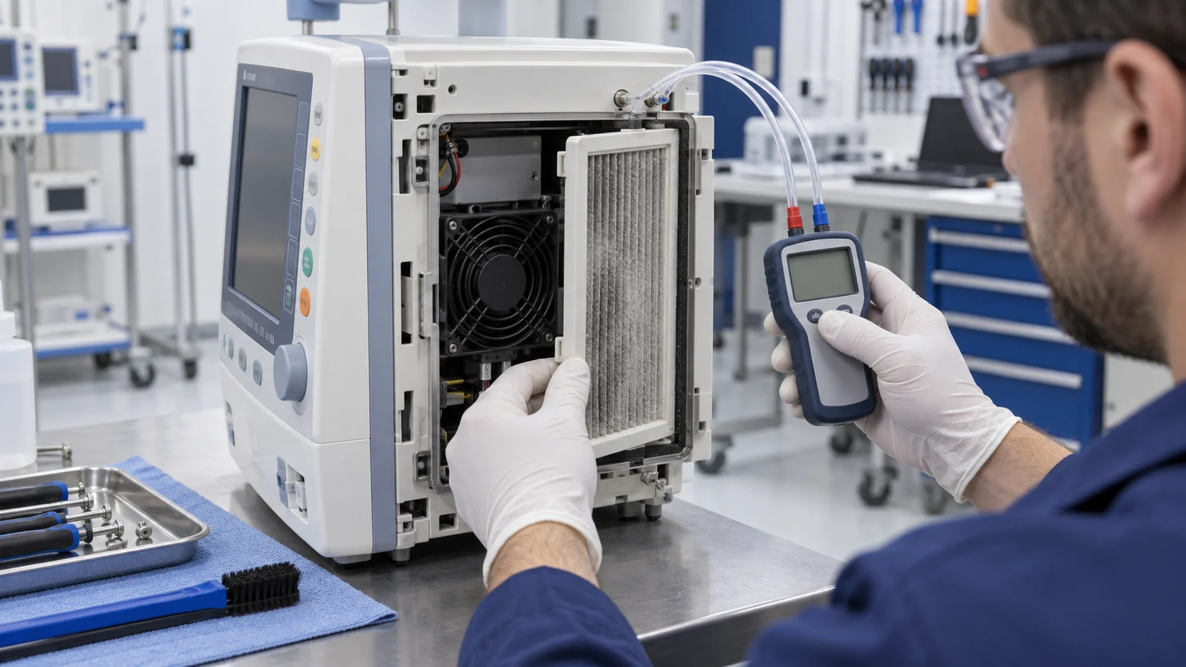
A simple service method may record clean-filter differential pressure, loaded differential pressure, fan command, RPM and protected temperature. If the service reading approaches the validated limit, the device can request filter replacement or inspection. If the device cannot measure pressure, a validated temperature trend or runtime/service indicator may be used as a proxy, but its limitation must be documented.
After filter replacement, repeat the functional check. Confirm airflow direction, gasket seating, fan restart, alarm reset, protected temperature and any acoustic or EMC-sensitive state affected by the changed load. A new filter can also alter pressure enough to change fan speed, noise or current, so ‘replacement completed’ should not be the only record.
Use contamination and cleaning boundaries carefully. If a filter can contain contaminated material, the service procedure must define PPE, disposal and seal handling. The fan supplier can help with the cooling sample and environmental boundary; the device manufacturer owns the approved maintenance and infection-control procedure.
Use a Four-State Thermal Validation Plan
Clean, loaded, blocked and post-service states expose different failure paths.
State one is clean and normal: establish the reference pressure, airflow proxy, temperatures, current, RPM and acoustic condition. State two is service-loaded: use a controlled resistance or a defined aged filter condition, then repeat the same measurements. State three is restricted or bypass-challenged: test only within a safe device procedure and verify the expected alarm or derating response. State four is post-service: reinstall the filter and confirm that the original cooling and alarm behaviour returns.
Do not use an arbitrary percentage reduction as a universal filter multiplier. The filter media, face area, dust type, humidity, frame and fan curve determine the result. A useful acceptance report states the actual pressure and airflow method, filter condition, measurement uncertainty, device mode and protected temperature limit.
Compare reference and candidate fans in the same filter and fixture. If the candidate needs a higher command to hold temperature, record the impact on sound, current, bearing duty and controller headroom. If it needs a lower command, verify minimum startup and feedback. A lower-cost sample is not a successful replacement if maintenance margin becomes smaller.
| State | Record | Release question |
|---|---|---|
| Clean | ΔP, airflow proxy, RPM, current and temperatures | does the new assembly meet the normal contract? |
| Loaded | same measurements with defined resistance | is margin preserved at service condition? |
| Restricted | alarm, derate, temperature and recovery | does the device respond safely to a cooling loss? |
| Post-service | seal, direction, restart, reset and temperatures | can maintenance restore the validated state? |
How MEGA Tech Can Support a Medical Fan and Filter Review
MEGA Tech can help match a fan to the installed pressure path while the device manufacturer owns the medical maintenance and compliance decision.
MEGA Tech develops custom DC axial fans and compact blowers for medical and laboratory equipment where airflow, static pressure, noise, temperature, control and reliability must be defined together. The review may include frame or thickness, connector and cable, PWM or voltage response, FG/RD feedback, bearing configuration, airflow direction, mounting detail, inlet temperature and replacement compatibility.
Provide the filter media and frame, clean and service pressure, face area, duct or grille drawing, protected load, voltage and control interface, feedback expectation, ambient and cleaning conditions, acoustic limit, duty cycle, maintenance state and first-build quantity. If replacing a known Sanyo Denki, SUNON, Delta, NMB or ebm-papst fan, include the installed working point and filter condition rather than only the part number.
We can build a small first sample and provide fan-side measurements across the declared states. We do not issue medical-device certification, filter certification, infection-control approval or clinical claims. The device maker owns the risk management, maintenance procedure, essential-performance definition and final release.
Representative Filter-Service Review
An anonymous example shows why filter loading should be connected to temperature and maintenance evidence.
Consider a compact medical electronics cabinet used in a controlled clinical environment. Its original fan passed the factory thermal test behind a clean inlet filter. After extended service, the fan still reported normal RPM, but the controller temperature rose during the longest operating mode and the service team began replacing fans without a clear pattern.
The review measured clean-filter differential pressure, loaded-filter differential pressure, fan current, RPM, inlet temperature, protected electronics temperature and outlet temperature. It also checked the gasket and frame for bypass. The loaded filter had increased resistance, while a small frame gap allowed part of the air to avoid the media. The pressure reading alone therefore understated the resistance seen by the intended cooling route.
The team defined a service trigger using the installed pressure and protected temperature trend rather than a generic calendar interval. After filter replacement, the device was checked for seal, fan direction, startup, alarm reset and thermal recovery. The candidate fan was then tested with both clean and service-loaded filters. The sample was not accepted because it was ‘stronger’; it was accepted only after it met the declared interface and thermal contract in both states.
This is an illustrative engineering scenario, not a named customer result, a clinical claim or a universal maintenance interval. Its transferable lesson is that a filter, fan and service procedure must be released together. A supplier can help measure the fan-side evidence, while the medical device maker owns the final maintenance and safety decision.
Recommended Fan Starting Points
These catalogue series may be suitable starting points for this application. Final selection depends on the installed airflow, static pressure, voltage, noise target and operating environment.
Request a sample for validation on your equipment.
Engineer FAQ: Medical Fan Filter Loading
Use these questions before approving a filter, fan or maintenance interval.
Q: Does a normal fan RPM prove the filter is acceptable? A: No. RPM confirms rotation. Validate pressure or airflow, protected temperature and the declared service state.
Q: Can a dirty filter be represented by a fixed 20% airflow reduction? A: Not universally. Media, face area, dust and fan curve determine the installed result; measure or bound the actual condition.
Q: Should the fan run faster as the filter loads? A: Only if the controller, noise, current, life and thermal margin support it. A higher command may hide a developing maintenance problem.
Q: What should happen after filter replacement? A: Confirm seal, direction, restart, alarm reset, pressure/airflow and protected temperature; record the service state.
Q: Can the fan supplier define the medical cleaning interval? A: The supplier can provide environmental and fan evidence, but the device manufacturer owns the approved cleaning, disposal and maintenance procedure.
Q: What can MEGA Tech customize? A: Frame, thickness, airflow direction, connector, cable, PWM, FG/RD, bearing, pressure/airflow duty and mounting details can be reviewed around the medical equipment requirement.
Questions for the Filtered Medical Cooling Review
A short checklist prevents a clean-filter bench result from becoming a field failure.
- What are clean, service-loaded and restricted pressure conditions?
- Where are the pressure taps, and how has filter-frame bypass been excluded?
- What protected temperature and airflow evidence defines essential performance?
- Does the controller detect only rotor loss, or also a blocked path through another validated signal?
- What are the voltage, PWM, FG/RD, startup and warm-restart requirements?
- What acoustic, EMC and current changes occur as resistance rises?
- What is the approved filter replacement, cleaning, disposal and seal procedure?
- What test repeats after service, and who owns the final maintenance interval?
- Which values are measured fan evidence and which require device-level validation?
- Has the candidate sample been tested with the actual filter and medical equipment interface?