An AMR Battery Pack Has a Moving Thermal Boundary
An autonomous mobile robot does not cool like a stationary cabinet. Its battery, BMS, charger interface and airflow path move through changing loads, vibration and warehouse conditions.
During a long mission, the battery may see repeated acceleration, lifting or traction peaks. At the dock, the pack may receive a high charging current while the robot is stationary and the surrounding air is still. The same enclosure can then spend hours idle, start in a cold warehouse or operate near dust and fibre sources. A fan selected from a single room-temperature test can miss the actual duty cycle.
The engineering question is not simply whether the battery has a fan. It is whether the installed fan and air path keep the cells, busbars, contactors, BMS and charger interface inside their allowed thermal and environmental envelope while preserving energy, acoustic and reliability targets. In many compact AMRs, the fan has very little space, a narrow grille and a cable path that creates more pressure drop than the early CAD model suggests.
This article gives AMR designers, battery engineers and procurement teams a practical validation method. The numerical examples are engineering estimates, not a claim about a named robot or battery. The battery and BMS owner remains responsible for cell safety, protection and certification; MEGA Tech supports the fan and air-side interface.
Map the Heat Sources Before Choosing the Air Path
The battery cells are only one part of an AMR thermal map. Local electronics can create the hottest surface even when their total wattage is modest.
Separate cell heat, busbar and contact resistance, BMS electronics, contactors, DC-DC conversion, charging interface and nearby motor or drive heat. During discharge, the current profile may be pulsed by acceleration and obstacle handling. During charging, the pack can see a sustained high current while the robot is stationary. A thermal model that uses only average mission power can understate the charge-state heat pulse.
Create a state matrix with battery current, voltage, SOC range, ambient temperature, charger power, fan command, actual RPM, inlet temperature, outlet temperature and the hottest measured cell or electronics point. Include the first minutes after a high-power mission and the first minutes after the charger starts. Heat stored in the pack and enclosure can keep rising after the electrical load changes.
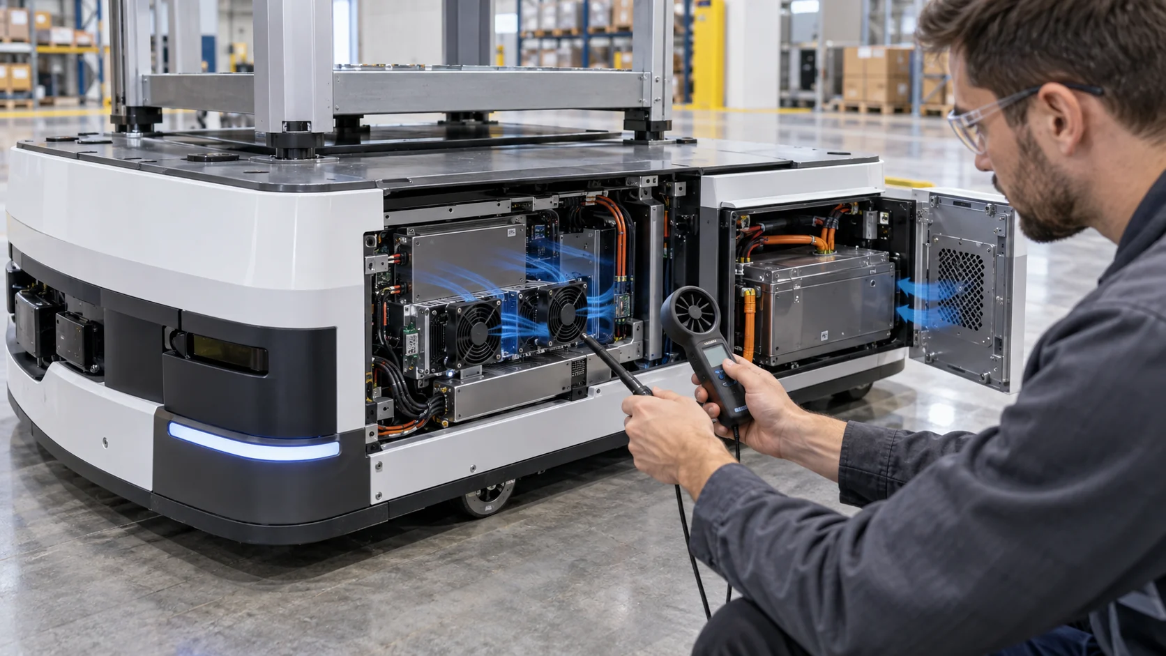
The airflow boundary should be drawn separately from the cell boundary. A fan may cool a heat spreader or an electronics bay without directly cooling every cell. If the design relies on conduction into a metal tray, measure the interface resistance and the effect of mounting pressure, thermal pads and vibration. Forced air is useful only when the path reaches the surface that limits the design.
Estimate Airflow From Charge Losses, Then Add Pressure
A simple heat balance provides a first target, but the fan must still be selected at the narrow battery-pack air path's real pressure.
Consider an illustrative 2.5 kWh AMR pack accepting a 4 kW charge. If the combined electrical and conversion efficiency during that condition is 94 percent, the approximate heat loss is 4,000 x (1 - 0.94) = 240 W. Add 20 W for BMS, contactor and auxiliary electronics and the cooling path may need to reject about 260 W. This is a screening example, not a battery specification.
If the team allows a 10 K average air rise, Q = P/(rho x cp x delta T). With an air heat-capacity estimate of 1,200 J/(m3 K), Q = 260/(1,200 x 10) = 0.0217 m3/s, or approximately 46 CFM. A lower local limit around a charger connector or power board may require more flow or a separate local path. Recirculation can also make the inlet hotter than the warehouse air.
Now include pressure. A compact grille, foam filter, battery tray, cable bundle and turning path may require 140 Pa at 46 CFM. The fan must deliver the target flow at 140 Pa and at the service-limit condition. A free-air rating of 46 CFM is not enough information. Record pressure, flow, voltage, current and FG/RD during the sample test so a replacement or production fan can be compared fairly.
| Input | Example | What it tells the team |
|---|---|---|
| Charge power | 4 kW | Defines the high-duty state |
| Estimated charge loss | 6% = 240 W | First electrical heat estimate |
| Auxiliary loss | 20 W estimate | Include BMS and contactor heat |
| Allowed average rise | 10 K | Sets about 46 CFM as a screen |
| Installed pressure | 140 Pa plus filter drift | Select on the loaded P-Q point |
Animated Model: Mission, Charging and Cold Start
The battery fan sees different airflow and heat conditions when the robot is moving, docked or waking in a cold warehouse.
During a mission state, the robot's own movement can change the inlet boundary and the fan may run from a battery rail that is falling with state of charge. During charging, the robot is stationary, the charger heat may be sustained and the dock can partially block the normal exhaust. During cold start, the fan lubricant, battery voltage and control response may all differ from the warm test.
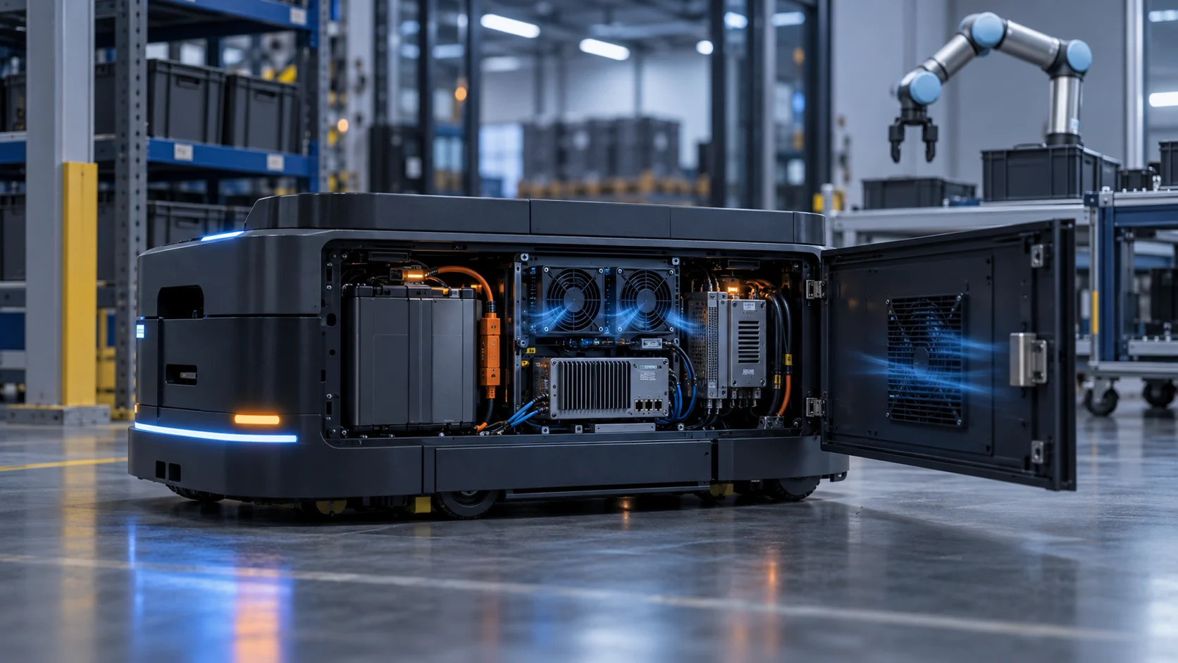
The animated schematic below uses blue particles for nominal air, amber particles for charge heat and red particles for a blocked or dock-restricted path. It is deliberately qualitative. Use it to define what should be measured, not to claim a CFD result. A good validation record repeats the same states with clean and service-limit filters, normal and low supply voltage, and the robot in its actual dock position.
If the fan is controlled only by cell temperature, the BMS may see a delayed response after a charge step. If it is controlled only by time, the system may waste energy during idle or fail to respond to a blocked path. Combine thermal feedback with fan feedback and a clear fault response, while keeping the battery safety functions independent of the fan supplier's scope.

High-Rate Charging Is Often the Limiting Fan State
An AMR can survive a short traction peak and still fail its charging-time thermal target if the docked pack cannot reject heat continuously.
The charging state deserves its own duty point. Measure charge current, pack voltage, cell temperature spread, charger interface temperature, fan command, actual RPM and inlet temperature together. The pack may be thermally asymmetric because the inlet reaches one side first, the heat spreader has different contact pressure across modules or the dock blocks a natural exhaust direction.
Use a step sequence rather than one steady charge run: begin at a low SOC, ramp to the intended charge current, hold the high-current state, reduce current near the upper SOC region and observe cooldown. Record the time from charge reduction to the hottest surface returning below the agreed limit. That recovery time can matter to fleet throughput and should be part of the requirement.
If the candidate fan reaches maximum command before the cell or connector limit is met, do not simply increase the command again. Check whether the air is bypassing the pack, whether the pressure curve is wrong, whether the heat path needs a spreader or whether the charger profile should be changed. A fan can only remove heat that reaches its air stream.
Cold Start, Low Voltage and Fan Restart
A fan that works at warm nominal voltage may not start or maintain useful airflow when the AMR wakes in a cold warehouse.
Cold environments change more than cell chemistry. Lubricant viscosity, bearing friction, elastomer stiffness, connector resistance and battery voltage can all affect the fan start. If the controller holds a low PWM duty during wake-up, the rotor may hesitate or repeatedly attempt to start. The result can be a silent loss of airflow before the thermal sensor has moved enough to trigger a higher command.
Define the minimum supply voltage, cold-start temperature, start command, start time, restart count and confirmed FG response. Test the fan after a long parked period, after a charge interruption and after a low-state-of-charge mission. Also test the same fan with the actual connector, cable length, filter and enclosure, not only with a laboratory harness.
A controlled start sequence can use a short higher-duty kick followed by a stable low-speed state, but the exact command depends on the fan and controller. The battery owner should also define whether a fan fault stops charging, reduces current, raises an alarm or changes the mission policy. The fan supplier can provide the signal and sample behavior; the system owner sets the safe response.
Vibration, Dust and Compact Airflow Geometry
An AMR fan must keep working while the chassis vibrates, the robot turns and warehouse dust accumulates at the inlet.
The fan mounting sees motor vibration plus road shock, docking impact and repeated acceleration. A flexible panel can amplify a tonal fan frequency, while a hard bracket can transfer vibration into the battery tray or sensor wiring. Measure vibration at the fan frame and at the pack structure. Check screw preload, gasket compression, cable restraint and the effect of a replacement fan's mass or connector position.
Dust protection creates another trade-off. A filter or mesh can protect the pack but increase pressure and reduce flow as it loads. Fibre, cardboard dust and fine warehouse particles can also change the balance over time. Test clean and service-limit conditions, and define whether the filter is replaceable without opening a hazardous battery compartment.
Compact AMR packages frequently have short bends, narrow slots and a fan close to a wall. The system curve can therefore rise quickly. Use a fan with a pressure-flow curve that still has margin at the installed duty, and verify that the outlet does not dump warm air back into the inlet when the robot is parked against the dock.
| State | Measure together | Decision |
|---|---|---|
| Mission peak | pack current, cell spread, fan feedback and inlet | check transient thermal margin |
| High-rate charge | charge power, connector temperature, flow and pressure | confirm continuous-duty point |
| Cold start | minimum voltage, start time, RPM and ambient | confirm restart reliability |
| Docked position | inlet/exhaust temperature and blocked clearance | check recirculation |
| Loaded filter | differential pressure, current and hotspot | set service alarm before derating |
Fan Feedback and BMS Boundaries
A battery-management system should know whether a cooling problem is caused by a fan fault, an airflow restriction or a heat source outside the fan path.
FG or tach feedback can confirm rotor movement and approximate speed. It cannot prove the required CFM at pressure. Add pressure, temperature trend or a service sensor where the design needs to distinguish a normal fan from a blocked path. RD or locked-rotor feedback can help create a fast fault response, but it does not replace the battery's protection logic.
Define what happens when the fan is disconnected, locked, slow, intermittently connected or running against a loaded filter. Does charging reduce current? Does the robot return to the dock? Does the BMS open a contactor? Does the fleet system record a service code? Test the behavior with the robot stationary and during a representative mission state.
Keep the scope clear. MEGA Tech can support fan voltage, PWM, FG/RD, connector and sample behavior. The battery and robot owner remains responsible for cell limits, isolation, contactor control, fire strategy, charging approval and the safe system-level response.
An Anonymized AMR Battery Validation Example
A useful case study separates charging heat, mission heat and dock airflow instead of treating the pack as one steady load.
In an anonymized warehouse AMR development, the battery pack passed a bench charge test but showed a larger-than-expected module temperature spread when the robot charged in its dock. The fan RPM was within the expected range. Inspection found that the dock clearance redirected warm air toward the inlet, while a foam filter and cable bundle created additional pressure. The cold-start test also showed delayed fan restart after an overnight park.
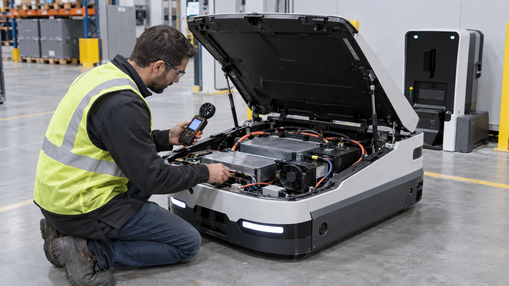
The engineering sequence began with a populated-pack pressure and temperature map. The team recorded current, voltage, inlet and outlet air, module temperatures, fan command, actual RPM, differential pressure and dock position. A custom high-static-pressure axial sample was compared with a compact blower at the same envelope and voltage. The start profile, FG response and loaded-filter condition were included in the comparison.
The customer then revised the dock clearance, adjusted the inlet and outlet path and chose a fan configuration that retained pressure margin at the service condition. The battery and BMS limits remained system responsibilities. The transferable lesson is that a mobile robot's charging position is part of the cooling assembly; a fan that works on the bench can be underpowered when the AMR is parked in its real dock. This is an anonymized engineering scenario, not a named customer result.
How MEGA Tech Supports Custom AMR Battery Fans
MEGA Tech helps robotics teams convert a compact battery enclosure into a fan sample that can be tested on the actual robot.
We can review custom DC or EC axial fans, compact centrifugal blowers and fan modules for battery packs, charger interfaces, controller bays and robot electronics. The review can include pressure-flow behavior, 5/12/24/48 V operation, PWM or voltage control, FG/RD feedback, cold start, bearing selection, vibration-sensitive mounting, connector position, dust or moisture construction and small-batch samples.
For a first review, send charge and mission heat by state, airflow path, target airflow at static pressure, fan envelope, battery voltage range, minimum supply voltage, control interface, connector, noise target, vibration environment, filter condition, cold-start requirement, quantity and safe fault response. A current fan part number is useful for replacement work, but same frame size, voltage or RPM alone does not prove equivalence.
Our boundary is clear: MEGA Tech does not certify cells, the BMS, the charger, the robot motion system, fire protection or regional battery approval. We support the fan and air-side interface, build engineering samples and help the customer validate the result on the populated AMR and charging dock.
Recommended Fan Starting Points
These catalogue series may be suitable starting points for this application. Final selection depends on the installed airflow, static pressure, voltage, noise target and operating environment.
Request a sample for validation on your equipment.
Engineer FAQ: AMR Battery-Pack Fan Validation
Use these questions when reviewing a battery enclosure, fan supplier or charging-dock thermal test.
Q: Does a higher battery capacity require a larger fan? A: Not necessarily. Fan duty follows heat loss, allowed temperature rise, enclosure resistance and the actual surface reached by the air.
Q: Is the charging state more important than the mission state? A: It can be. The robot is stationary, the charge heat can be continuous and the dock can change the inlet and exhaust boundary.
Q: Does normal RPM prove normal cooling? A: No. Pressure, filter loading, bypass, dock clearance and airflow distribution can reduce cooling while RPM remains normal.
Q: How should cold start be specified? A: Define ambient temperature, minimum battery voltage, PWM command, start time, restart count and confirmed FG behavior with the real connector and enclosure.
Q: Can a filter be added without changing the fan? A: Only after clean and service-limit pressure-flow and temperature tests show sufficient margin.
Q: Should battery and controller fans share one curve? A: Not automatically. They may see different heat sources, pressure paths, contamination and fault priorities.
Q: What information should I send MEGA Tech? A: Send heat by mission and charge state, airflow at pressure, fan envelope, voltage, PWM/FG/RD, connector, noise, vibration, dust, cold-start and quantity.
Q: Can MEGA Tech replace a branded AMR fan? A: We can evaluate a cost-competitive replacement, but equivalence must be proven on the installed operating point and populated robot.
AMR Battery Cooling Design Review Checklist
Record these decisions before freezing the fan, filter, dock interface and control logic.
- What are the mission, peak acceleration, fast-charge, idle and cold-start heat states?
- Which components are air-cooled, conduction-cooled or isolated from the fan path?
- What airflow and static pressure are required at clean and service-limit conditions?
- Does the real charging dock alter the inlet, outlet or recirculation path?
- What are the minimum battery voltage and cold-start temperature for fan restart?
- Have vibration, mounting preload, cable restraint and tonal noise been tested on the moving robot?
- Can FG/RD distinguish a fan fault from a blocked filter or low airflow condition?
- What happens to charge current and robot behavior after a fan fault?
- Can the filter or fan be serviced without opening an unsafe battery compartment?
- Which results are measured, which are estimates and which belong to the BMS or robot owner?