A Mobile Robot Has a Different Cooling Problem from a Fixed Cabinet
An AMR or cobot can pass a bench test and still lose thermal margin during fast charging, sustained navigation, payload motion or a sealed-door service cycle.
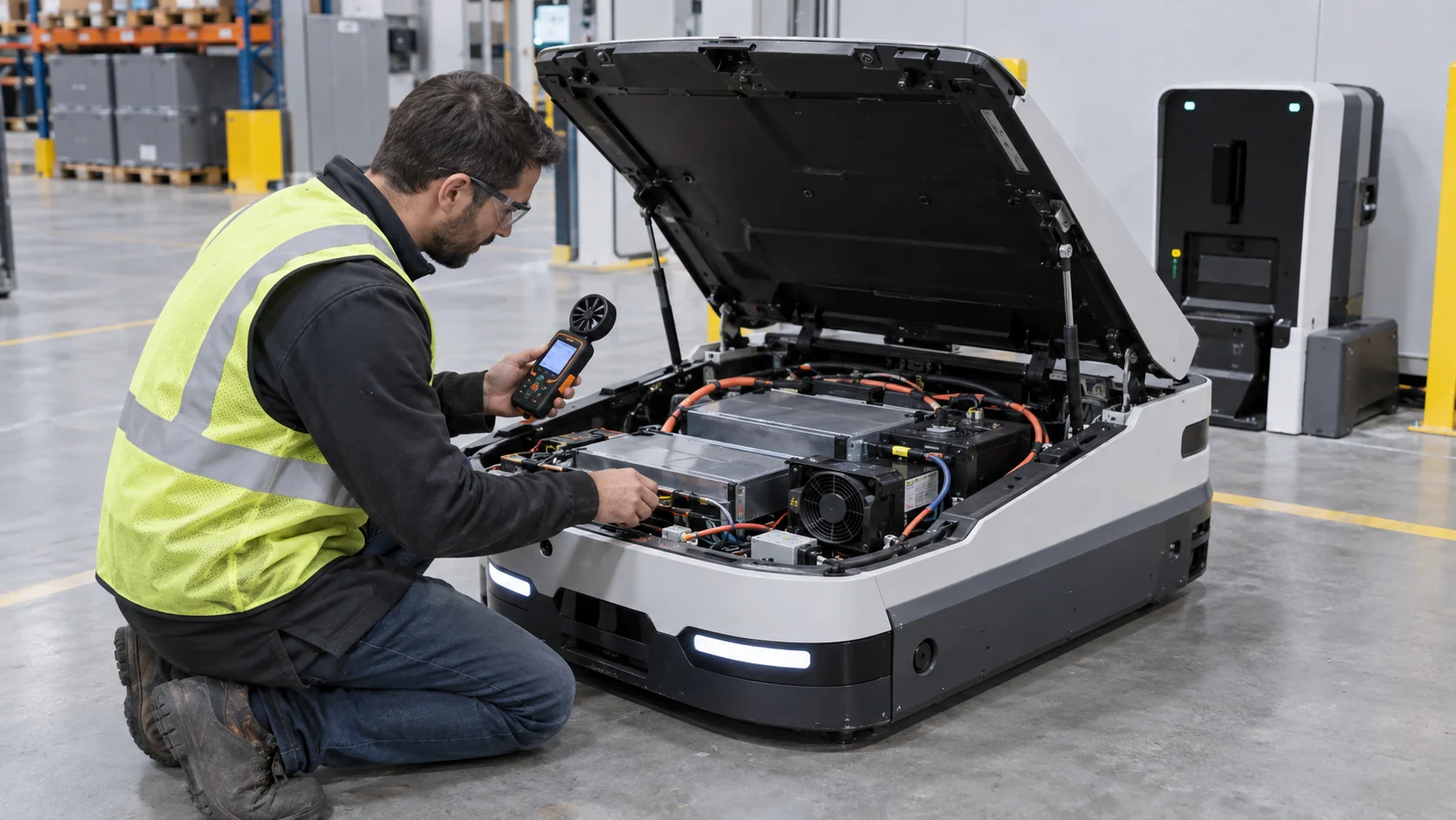
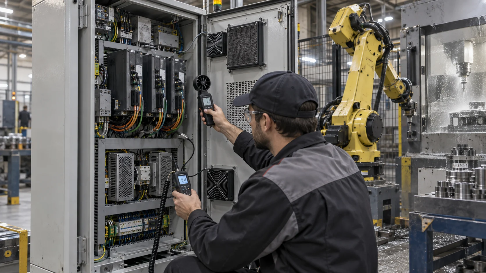
A fixed control cabinet usually has a predictable installation, a known exhaust direction and enough space to separate the inlet from the hot outlet. A mobile robot does not. Its battery, motor inverter, DC-DC converter, safety controller, vision computer, wireless module and charging hardware compete for volume. The platform may move from a cool aisle to a warm loading bay, then enter a charging station where the electronics remain powered while the battery is accepting energy.
The thermal load also changes with behavior. Wheel acceleration raises inverter loss; payload motion raises actuator and brake loss; computer vision raises processor power; and a fast-charge event adds heat to the battery, charger and conversion path. A small fan selected from free-air CFM can therefore look adequate in a short demonstration but fail after the enclosure, grille, dust filter, cable bundle and acoustic cover are installed.
This guide focuses on the air-side decisions an OEM should validate before freezing a fan: where the heat is generated, where the air is allowed to travel, how pressure changes when the filter loads, how noise is perceived near people, and how the fan behaves while the robot is moving. It does not replace the robot manufacturer's electrical, battery, EMC or functional-safety requirements.
Map the Heat by Operating State, Not by Component Nameplate
The first useful thermal model is a state table that connects robot behavior to watts, temperature and fan command.
Separate at least five states: idle with the safety system active, normal navigation, maximum acceleration with payload, high-compute perception and charging. Record battery current, motor current, processor utilization, DC bus voltage, fan command and ambient temperature for each state. If the platform has a lift, arm or gripper, include the motion that creates the highest repeated duty instead of relying on a single peak event.
As an engineering estimate, consider an AMR with two drive inverters dissipating 55 W each during heavy motion, a compute and networking stack at 85 W, a DC-DC stage at 35 W and battery/charger electronics at 65 W. The enclosure heat load is approximately 295 W in that state. If the design allows a 12 C air rise, the ideal air mass flow is 295/(1005 x 12) = 0.0245 kg/s, or roughly 74 m3/h at room density before pressure losses, recirculation and margin are included.
That estimate is a starting point, not a fan selection. The actual operating point depends on the P-Q curve and the installed system curve. A fan that advertises 100 m3/h at zero pressure may deliver substantially less through a narrow grille, filter, acoustic foam and a 90-degree internal turn. Validate temperature at the hottest component and at the exhaust, then compare the result with the fan command and feedback signal.
| State | Record | Engineering question |
|---|---|---|
| Idle / ready | ambient, standby power, minimum fan duty | Does the fan start reliably without unnecessary noise? |
| Normal motion | drive current, compute load, inlet and hotspot temperature | Where is the steady operating point? |
| Peak motion | acceleration, braking, temperature rise and recovery | Does the short high-load event consume the margin? |
| High compute | camera/AI utilization, processor temperature and airflow | Does the electronics zone receive enough flow? |
| Fast charge | charge power, battery temperature and enclosure temperature | Can charging and cooling operate together safely? |
The Installed Path Is Usually the Real Constraint
Compact robot housings lose pressure margin through small openings, protective screens and internal routing long before the fan reaches its catalogue maximum.
Measure the complete air path: inlet grille, filter or mesh, battery-side baffle, heat sink fins, fan guard, cable opening, acoustic treatment and outlet. The pressure drop is not only the resistance of the fan guard. A battery pack can block a large part of the cross-section, forcing air through a narrow corridor where velocity and loss increase. A gasket can also create an unintended bypass around the filter, reducing protection while making a simple pressure measurement look better than the thermal result.
For a practical calculation, suppose the clean inlet and grille contribute 24 Pa, the filter contributes 36 Pa, the electronics duct contributes 48 Pa, the heat sink and fan guard contribute 31 Pa, and the outlet contributes 21 Pa. The clean installed path is about 160 Pa. If the filter reaches 72 Pa in service, the path becomes about 196 Pa. The fan must be checked at both points, not only at the clean state.
On a moving robot, the outlet must also be checked in the real position. A wall, charging dock or adjacent robot can recirculate warm exhaust into the intake. Use smoke, tufts or a simple temperature tracer during a docked test, and repeat the measurement with the service panel closed. Airflow direction marks on the fan frame are useful, but only the installed measurement proves the path is doing what the design intends.
Interactive: See What Changes When the Robot Accelerates
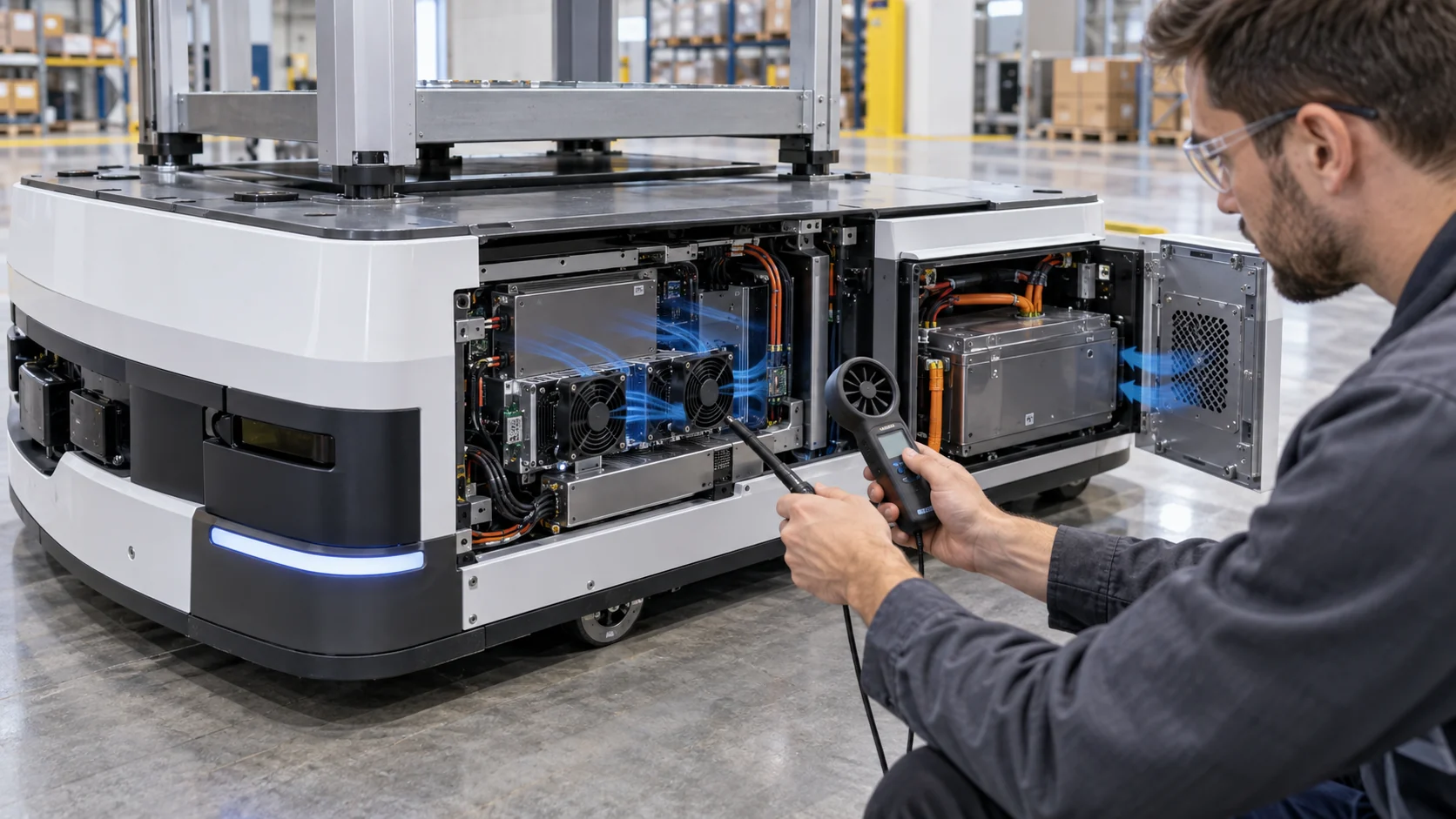
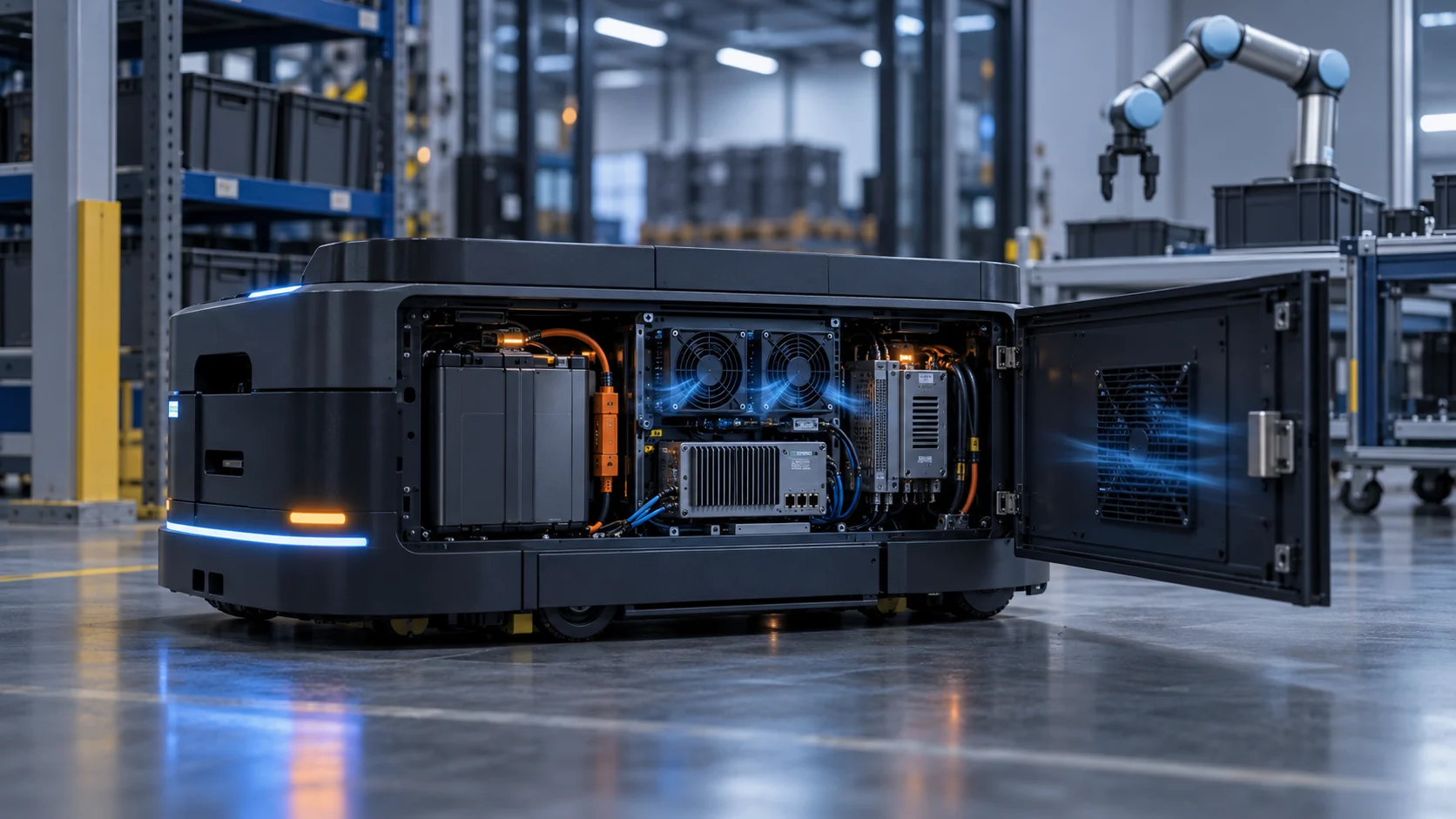
This qualitative schematic separates battery heat, drive heat and compute heat so the test plan does not hide one hot zone behind an average enclosure temperature.
Use the visual to define three practical test states: low-speed travel, repeated acceleration with payload and charging while the compute system remains active. At each state, measure the temperature of the battery enclosure, inverter heat sink, processor heat sink and air leaving the cabinet. A single sensor on the fan outlet can miss a local drive hotspot, while a single battery sensor can miss a compute module that is thermally isolated from the pack.
If the robot uses separate loops, keep them separate in the test record. Battery air, inverter air and compute air may require different pressure, noise and contamination priorities. Combining them through one small fan can create recirculation or force a low-pressure zone at the component that needs the most heat removal. A baffle or duct can be more effective than simply increasing RPM.
The animation is not a CFD result, a product rating or a robot-specific thermal limit. It is an engineering explanation of why the same fan command can produce different temperatures when the motion state, filter condition or air path changes.

Battery, Drive and Edge-Compute Cooling Need Different Evidence
A mobile robot's thermal zones are related, but they should not be accepted using one average temperature or one fan speed signal.
Battery cooling is usually constrained by cell temperature spread, charging temperature and the allowable rate of heat rejection. Drive cooling is constrained by switching and conduction losses, heat sink temperature and repeated acceleration. Edge compute is constrained by processor junction temperature, throttling and local airflow resistance. The most useful measurement points are therefore distributed across zones rather than concentrated at the inlet.
For the battery, compare the hottest cell or module with the coolest one during a charge/discharge cycle. For the drive, measure the heat sink near the switching devices and record the recovery time after a peak move. For the compute module, record processor utilization, clock behavior and inlet air temperature. A fan can reduce one temperature while increasing another if the flow path is not balanced.
If the robot works around people, acoustic evidence matters as well. Record A-weighted sound pressure at the operator position, but also listen for tonal blade-pass peaks, bearing noise and speed hunting. A lower average dBA value can still be unacceptable if a narrow tone is noticeable in a quiet warehouse or charging room. PWM frequency, speed ramp and control hysteresis should be tested with the fan mounted on the final panel.
Sealing, Dust and Noise Create a Three-Way Trade-Off
A sealed mobile platform protects the electronics, but the same boundary can make heat removal and fan service more difficult.
Start with the environment instead of choosing an IP-rated fan from a catalogue. Warehouse dust, cardboard fibres, floor debris, food particles, cleaning chemicals, condensation and washdown have different effects on a filter, bearing and connector. A fan mounted behind a filter may need less direct protection than a fan exposed to the outside, but the filter pressure and service interval become more important.
If the housing is intended to keep dust out, inspect every fan cut-out, cable gland, service door and pressure equalization path. An IP-rated fan cannot compensate for a loose panel or a bypass gap around the filter. If the enclosure is sealed, consider a heat exchanger or closed-loop module and verify its added pressure and thermal resistance. If the enclosure is vented, define the filter replacement threshold from differential pressure and temperature evidence.
Noise must be evaluated in the real operating environment. A robot with a high-speed fan can be quiet in a large factory and irritating in a charging bay or collaborative workstation. A larger fan at lower speed may reduce tonal content, but it needs space, protection and a validated starting behavior. MEGA Tech can compare axial and blower options when a compact outlet or high static pressure makes a simple axial arrangement unsuitable.
Control the Fan From the Limiting Zone, Not From the Nearest Sensor
PWM or EC control can extend battery runtime and reduce noise, but only when the feedback signal represents the component that actually limits the robot.
A fan near the inlet can see cool air while the drive heat sink downstream is already hot. A sensor on the battery case can remain stable while the edge computer throttles. Place the primary sensor at the limiting zone and use current, charge power or compute utilization as a feed-forward signal where appropriate. Add hysteresis and a minimum runtime so the fan does not hunt around a narrow temperature threshold.
For an illustrative energy estimate, two 24 V fans drawing 0.20 A each consume 9.6 W at full command. If they run at 40% of that input for 10 hours of travel and full input for 2 hours of charging, the idealized fan energy is about 9.6 x (0.4 x 10 + 2) = 57.6 Wh per day. The estimate excludes controller losses and does not prove battery-range improvement, but it shows why a validated variable-speed strategy can matter on a mobile platform.
Test the abnormal states explicitly: fan disconnected, locked rotor, FG signal missing, temperature sensor unplugged, filter pressure high and controller restart at low temperature. The robot should enter a defined protective state rather than silently accepting a normal-looking command. A tachometer signal proves rotation; it does not prove that air reaches the intended heat sink.
An Anonymous Customer Example: A Charging-Bay Hotspot on an AMR
A European logistics-robot developer found that its AMR was stable during warehouse travel but overheated when the vehicle arrived at a warm charging bay with the computer still active.
The first prototype used one compact axial fan drawing air across the battery-side electronics and exhaust through a narrow rear grille. During normal travel, the platform remained within the expected temperature range. During charging, however, the battery and charger added heat while the vision computer continued processing. The fan remained at the programmed speed, but the heat sink near the DC-DC stage became the limiting zone.
MEGA Tech reviewed the enclosure section, fan command, filter opening, charging duty, compute workload and exhaust position. The team measured the clean and service-state pressure, mapped temperatures at the battery, inverter, converter and processor, and compared an axial sample with a compact blower at the installed path. The customer also tested a revised baffle so the air did not bypass the converter heat sink.
The resulting design used a pressure-matched fan sample, a revised inlet seal and a control curve that increased airflow during charging before the hotspot reached the protection threshold. The customer retained FG feedback and added a filter-pressure inspection to the service procedure. The important outcome was not a catalogue airflow claim; it was a repeatable test that connected charge power, compute state, fan operating point and hotspot temperature.
This is an anonymized engineering scenario, not a published customer performance claim. The transferable lesson is to test the robot in its most thermally coupled state, especially when charging and computation occur at the same time.
| Test state | Measurements | Decision |
|---|---|---|
| Travel | drive current, fan command, inlet and hotspot temperature | confirm the normal operating point |
| Acceleration | peak temperature, recovery time and vibration | check transient margin and mount behavior |
| Charging | battery/charger power, converter and compute temperature | verify the coupled heat load |
| Loaded inlet | filter pressure, fan current and airflow | define the service threshold |
| Fault injection | FG loss, sensor loss, fan stop and restart | confirm controlled protection |
How MEGA Tech Helps Robotics OEMs Move From Sample to Production
A custom cooling fan is valuable when it is matched to the robot's real interface, duty cycle and production constraints rather than treated as an isolated component.
MEGA Tech can review axial fans, compact blowers and fan modules for AMR battery compartments, cobot control electronics, vision processors, servo drives, charging stations and mobile service robots. The engineering review can include P-Q behavior, filter pressure, fan direction, PWM or voltage control, FG/RD feedback, startup, vibration, bearing selection, IP and corrosion exposure, noise, connector position and small-batch sampling.
For a first review, provide the robot enclosure drawing, heat sources or measured loss, travel and charge profiles, ambient and process conditions, inlet and outlet restrictions, filter data, voltage, control signal, feedback requirement, noise limit and quantity forecast. A short thermal log during the real robot program is more useful than a single idle temperature. If the application is still at prototype stage, photographs and a rough heat map are enough to start a practical sample discussion.
We also support cost-competitive replacement fans for Sanyo Denki, SUNON, Delta, NMB and ebm-papst when the replacement is verified at the same installed pressure, voltage, mounting, feedback and environmental condition. A frame-size match is only the first check. The production decision should follow the measured operating envelope and the robot's service strategy.
Engineer FAQ: Cobot and AMR Cooling Fan Selection
These questions connect fan selection to battery duty, motion, charging, sealing and practical maintenance.
Q: Can I size an AMR fan from battery capacity? A: Battery capacity is not the heat load. Use measured or estimated losses during travel, acceleration, charging and compute operation.
Q: Why does the robot stay cool while moving but heat during charging? A: Charging can add battery and converter heat while the compute system remains active; the combined state must be tested.
Q: Is a higher IP rating always better? A: Not automatically. The complete housing, fan cut-out, filter, gasket, connector and service plan determine protection and thermal resistance.
Q: Should I use an axial fan or a blower? A: Use the installed pressure and space. Axial fans suit lower-pressure paths; blowers can be useful where a narrow duct or heat sink creates higher static pressure.
Q: Does a normal RPM signal prove cooling performance? A: No. RPM proves rotation, not distribution, filter condition or pressure-flow performance at the heat sink.
Q: How should fan noise be tested on a cobot? A: Test the final mount, control curve and operator position, including tonal peaks and speed hunting rather than only a single maximum dBA value.
Q: Can MEGA Tech support a low-volume robotics prototype? A: Yes. We can adjust fan parameters and interfaces, build samples and support thermal, pressure, vibration, noise and environmental validation before production.
Cobot and AMR Cooling Review Checklist
Use this checklist before freezing the fan, enclosure opening, filter, control curve or charging-state thermal limit.
- Was the fan selected from measured or estimated losses in travel, acceleration, compute and charging states?
- Were battery, inverter, converter and processor temperatures measured separately?
- Were grille, filter, baffle, cable routing, heat sink and outlet losses included in the installed path?
- Was the clean and service-state filter pressure tested?
- Was the docked or charging-bay exhaust recirculation checked?
- Were PWM/EC minimum duty, startup, FG/RD feedback, restart and control hysteresis verified?
- Was the final fan mount tested for vibration, shock, cable flex and connector retention?
- Were dust, fibres, oil, humidity, condensation, cleaning and washdown considered?
- Were operator-position noise, tonal peaks and speed hunting checked?
- Were fan, sensor, filter and thermal faults tested with a controlled protective response?
- Are estimates, measured values, OEM limits and machine-safety requirements clearly separated?