A Sealed Robot Cabinet Can Still Run Out of Cooling Margin
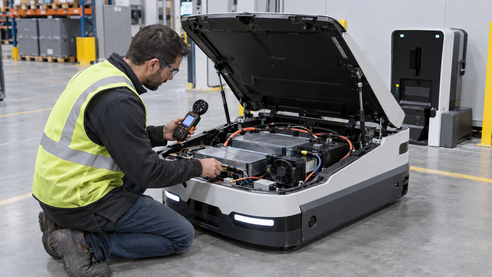
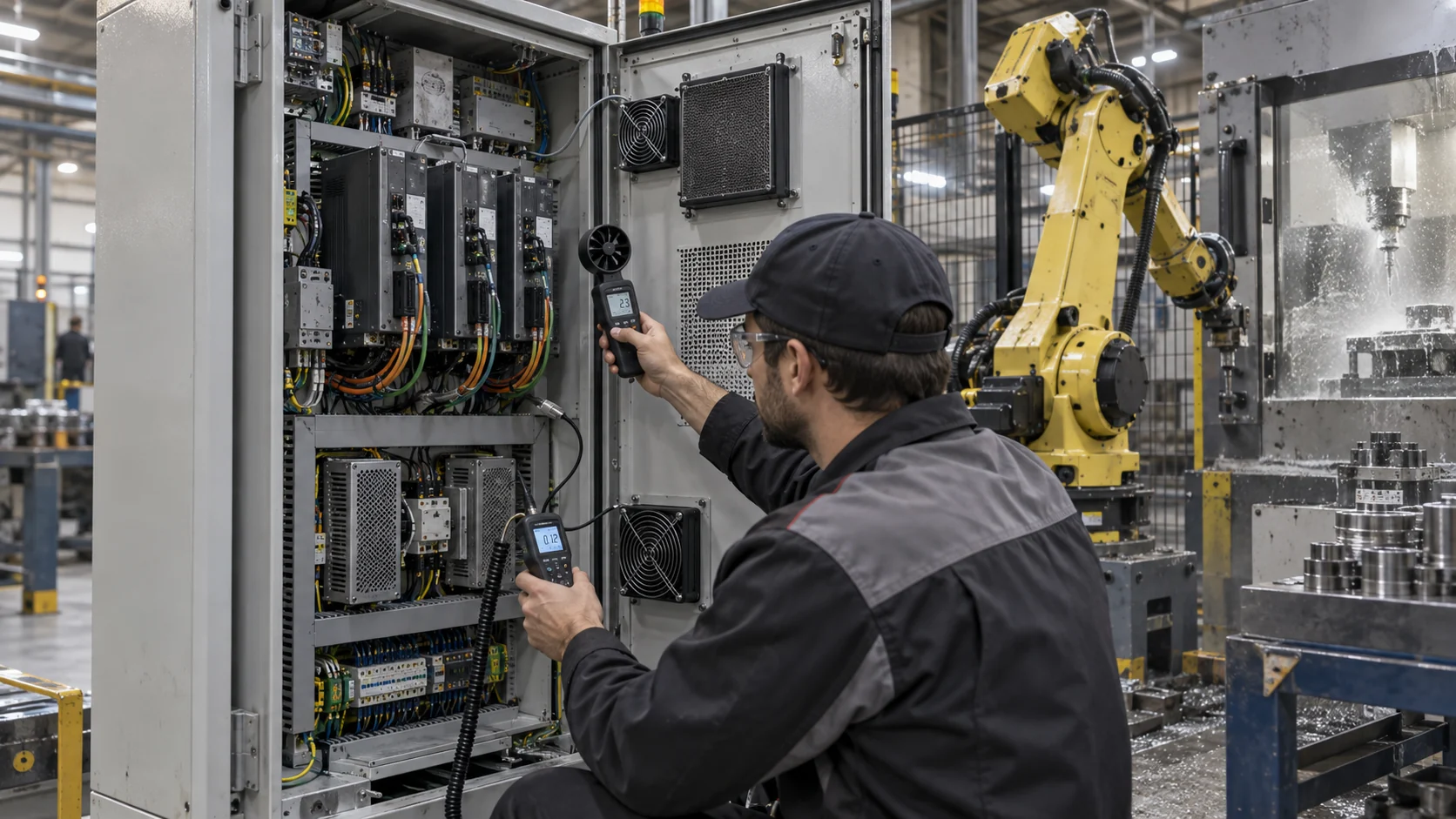
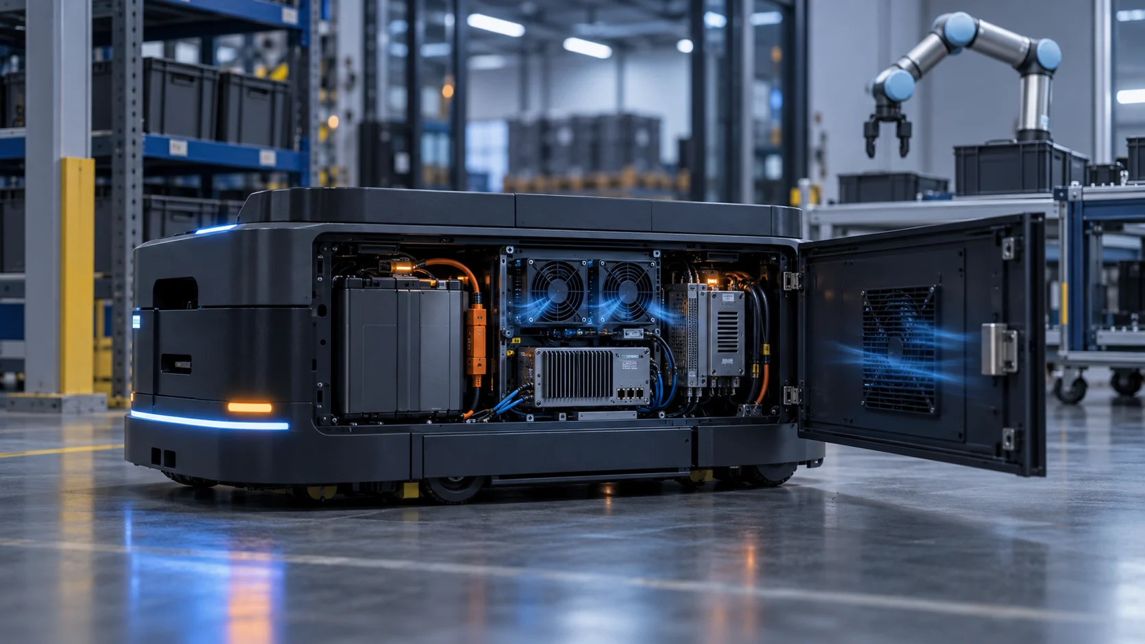
An AMR control cabinet has to protect electronics from dust and moisture while rejecting heat from the controller, motor drives, DC-DC converter and edge computer.
The difficult part is that the design requirements push in opposite directions. A tighter enclosure reduces contamination ingress, but the grille, filter, gasket and narrow duct add resistance. A larger fan may recover airflow, but it consumes battery energy, adds acoustic output and can transmit more vibration into a mobile chassis.
This article is a practical engineering guide for AMR, AGV and mobile-robot control cabinets. It focuses on the installed air path rather than a catalogue maximum-flow number. The correct question is not whether a fan can move air in free delivery; it is whether the complete cabinet can deliver the required air at its actual pressure, voltage, command and service condition.
The values in the examples are planning estimates, clearly labelled for calculation practice. Replace them with the robot maker's measured heat load, IP requirement, route profile and thermal acceptance limits before production release.
Start With Heat Load and Enclosure Resistance
A robot cabinet should be sized from the heat that must be removed and the pressure the installed path creates.
Separate the sources before selecting the fan: motor drives during acceleration, controller losses during continuous motion, edge-AI compute, DC-DC conversion and charging electronics. A route with low average motor power can still have short high-load events that determine the peak cabinet temperature. Charging may create a different thermal state again.
For a transparent estimate, suppose the cabinet must reject 120 W and the allowable air temperature rise is 12 K. Using Qv = P/(rho x cp x deltaT), with air density about 1.2 kg/m3 and heat capacity about 1.0 kJ/(kg K), the ideal flow is about 0.0083 m3/s, or 17.6 CFM. If the filter and grille cause the useful flow to fall to 13 CFM, the same simplified heat balance predicts about a 16 K rise. This is not a thermal acceptance limit; it shows why installed pressure matters.
A second estimate makes the energy tradeoff visible. A 24 V fan drawing 0.25 A uses about 6 W. If a control curve keeps it near 0.12 A for most of a shift and reserves higher speed for charging or peak motion, the average fan input is about 2.9 W instead of 6 W. The saving is modest compared with traction power, but it matters when a fleet repeats the duty thousands of times.
| Input | Why it matters | Evidence |
|---|---|---|
| Heat by operating state | Peak motion and charging may exceed route average | route and charge log |
| Filter and grille | Pressure loss moves the fan operating point | part number and loaded-state test |
| IP and contamination | Sealing can conflict with air exchange | dust, water, oil-mist and washdown condition |
| Motion and vibration | Bracket flex and clearance can change in service | mounting and motion test |
| Fan electrical interface | PWM, FG/RD and startup affect controller behavior | voltage tolerance and I/O definition |
IP Protection Is an Air-Path Decision, Not a Fan Label
A sealed fan does not automatically make an enclosure sealed, and a high IP target can create a pressure problem if the rest of the path is ignored.
Define what the enclosure must resist: warehouse dust, conductive particles, oil mist, water spray, washdown, condensation or a temporary outdoor exposure. The filter media, gasket compression, cable exit, service door and pressure balance are part of the protection strategy. Selecting an IP-rated fan while leaving an unsealed bypass gap does not deliver the intended cabinet protection.
The pressure budget should include the intake grille, filter at its maintenance limit, fan guard, bends, heat sink, exhaust path and any check valve or louvre. For a simple example, if the clean path is 45 Pa at the target flow and the loaded filter adds 90 Pa, the fan must deliver that flow at about 135 Pa before other uncertainties. A fan selected at free-air CFM has not yet answered this question.
For mobile equipment, a slightly positive filtered cabinet pressure may reduce uncontrolled dust entry, but it can also increase leakage through service gaps and add fan power. The design team should define where air is allowed to enter and leave, then verify that the intended path remains dominant when the robot is moving near walls, racks or a charging dock.
Interactive: See How Filter Loading Moves the AMR Duty
Switch between clean, service and high-resistance states to see why the same PWM command does not guarantee the same useful airflow.
The animation is a teaching model, not a universal fan curve. A production test should record fan command, voltage, FG or tach feedback, current, differential pressure, inlet temperature and the named controller and drive temperatures at the same time.
Use at least three states: clean filter and representative route, loaded or maintenance-limit filter, and charging or peak-motion heat load. If the fan reaches its command ceiling before the thermal target is met, increasing the nominal CFM number is not enough; the team must correct the path or select a fan with the required pressure capability.

Vibration Changes the Mechanical and Acoustic Result
A fan that is quiet and stable on a bench can produce noise, clearance loss or feedback dropout after it is mounted in a moving robot.
Review the bracket, fasteners, gasket, cable strain relief and impeller clearance together. The robot may experience floor joints, ramps, emergency stops, payload changes and repeated docking impacts. These events can change the alignment between the fan and guard or amplify a narrow tonal frequency through the cabinet panel.
The validation sequence should include a stationary baseline, representative motion, tilt, warm restart and minimum-voltage startup. Record acoustic output near the operator position and charging dock separately from drivetrain noise. A lower dB-A number on a bench does not prove a quieter installed robot if the mounting panel resonates.
For a first sample, MEGA Tech can adjust the frame, impeller, bearing configuration, mounting interface, control curve and connector arrangement around the customer's robot envelope. The purpose is not to claim a generic vibration rating; it is to expose the installed interface that the production team actually needs to control.
Control Logic Should Protect Both Temperature and Battery Runtime
PWM control is useful only when its minimum duty, startup behavior, feedback and hysteresis are validated on the actual fan and cabinet.
A temperature-only control loop can hunt when the sensor is close to a hot component but the cabinet has slow thermal response. Add a defined minimum speed for electronics protection, a peak state for charging or high motion, and enough hysteresis to avoid repeated command changes around one threshold. The final curve belongs to the robot controller team, but the fan sample must prove it responds predictably across the available voltage range.
FG or tach confirms rotor motion and approximate speed; it does not prove that air is reaching the heat source. RD or lock detection can support fault handling, but the controller should also consider temperature rise, current, pressure or another system-level signal where the risk justifies it.
Warm restart is a common blind spot. Test after the enclosure and battery are already hot, at the lowest declared supply voltage and with the filter in the representative service state. A fan that starts reliably on a cool bench may not recover after a charging cycle.
- Record PWM command, voltage, current and FG/RD together.
- Test clean and maintenance-limit filter states.
- Define minimum duty, peak duty, hysteresis and fault response.
- Repeat startup after route and charging heat soak.
- Treat normal RPM as feedback evidence, not airflow proof.
A Practical Acceptance Matrix for AMR Fan Selection
The acceptance matrix should make the tradeoffs visible to thermal, electrical, mechanical and procurement teams.
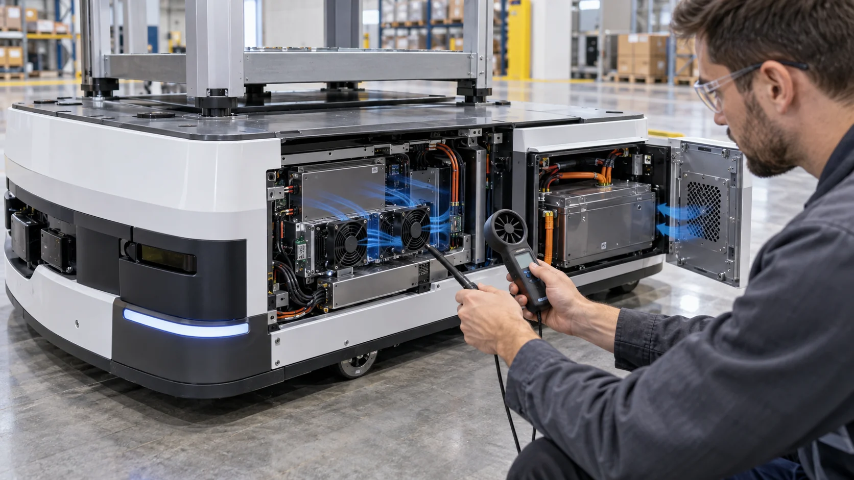
At minimum, compare the candidate fan at the installed pressure rather than only at free air. Record airflow or a calibrated proxy, differential pressure, fan current, speed feedback, temperature response and acoustic result. Repeat the comparison after the filter reaches the agreed maintenance condition.
If the robot has separate battery and controller paths, keep them separate in the test record. Combining them can hide a hot controller behind a healthy battery average or make a fan look effective because it short-circuits around the actual heat source.
A useful result is not necessarily the fan with the highest airflow. It is the sample that meets the thermal limit with controllable current, acceptable noise, stable feedback, serviceable filtration and enough pressure margin for the approved path.
Where MEGA Tech Fits In
We help robotics teams move from a crowded cabinet drawing to a fan sample that can be measured in the real robot.
MEGA Tech can review custom DC axial fans and compact centrifugal blowers for AMR and AGV controller cabinets, battery compartments, motor drives, edge-compute modules and charging electronics. The engineering review can cover airflow direction, frame and thickness, pressure-flow behavior, PWM or voltage control, FG/RD feedback, connector and cable exit, bearing choice, temperature range, vibration interface, noise and small-batch sampling.
For a first review, send the robot section drawing or sample, heat load by route and charging state, filter and grille details, target IP environment, voltage tolerance, control interface, available fan envelope, noise measurement point, vibration condition, service interval and expected quantity. A thermal image of the failure state and a short route log are often more useful than a catalogue part number alone.
We can also evaluate a cost-competitive replacement for Sanyo Denki, SUNON, Delta, NMB or ebm-papst fans when the replacement is judged at the same installed working point. The comparison should include the actual pressure, electrical interface, acoustic behavior, feedback and sample evidence rather than a nominal CFM claim.
Engineer FAQ: AMR and AGV Control Cabinet Cooling
These questions keep IP protection, fan selection and mobile-duty validation connected.
Q: Is an IP-rated fan enough for an IP-rated robot cabinet? A: No. The fan, gasket, filter, grille, cable exit, service panel and leakage path must be evaluated as an assembly.
Q: Should I select the highest-CFM fan available? A: No. Select from the installed pressure-flow working point and confirm current, noise, feedback and temperature response.
Q: Does a higher IP rating always improve cooling reliability? A: Not automatically. Tighter protection can add pressure loss and reduce airflow if the path is not designed and tested together.
Q: What should be tested after filter loading? A: Differential pressure, fan command, current, speed feedback, controller temperature and battery or drive temperatures at the same operating state.
Q: Can normal FG or tach feedback prove the cabinet is cool? A: No. It shows rotor motion, not the distribution of air through the cabinet.
Q: Why test a warm restart? A: Battery charging and route peaks can leave the cabinet hot while supply voltage is at a low or changing value. Startup margin must be proven in that state.
Q: Can MEGA Tech help with a small first build? A: Yes. We can review a customer sample, adjust fan and interface parameters, build samples and support installed validation before a larger production decision.
AMR Fan Design Review Checklist
Bring these questions to the thermal, mechanical, electrical and purchasing review before freezing the fan.
- What are the controller, drive, compute and charging heat loads in each operating state?
- What filter condition and pressure drop represent the service limit?
- Where are the intended inlet, outlet, bypass and recirculation paths?
- What IP, dust, oil-mist, humidity and washdown exposure must the assembly survive?
- Does the fan meet the required airflow at the installed pressure, not at free air?
- How much fan power can the robot spend without reducing the required runtime?
- Were motion, tilt, vibration, docking, warm restart and minimum-voltage startup tested?
- Were PWM, FG/RD, current, pressure and temperature recorded together?
- Can the operator service the filter and fan without unsafe battery access?
- Which results are measured, which are estimates and which require system certification?