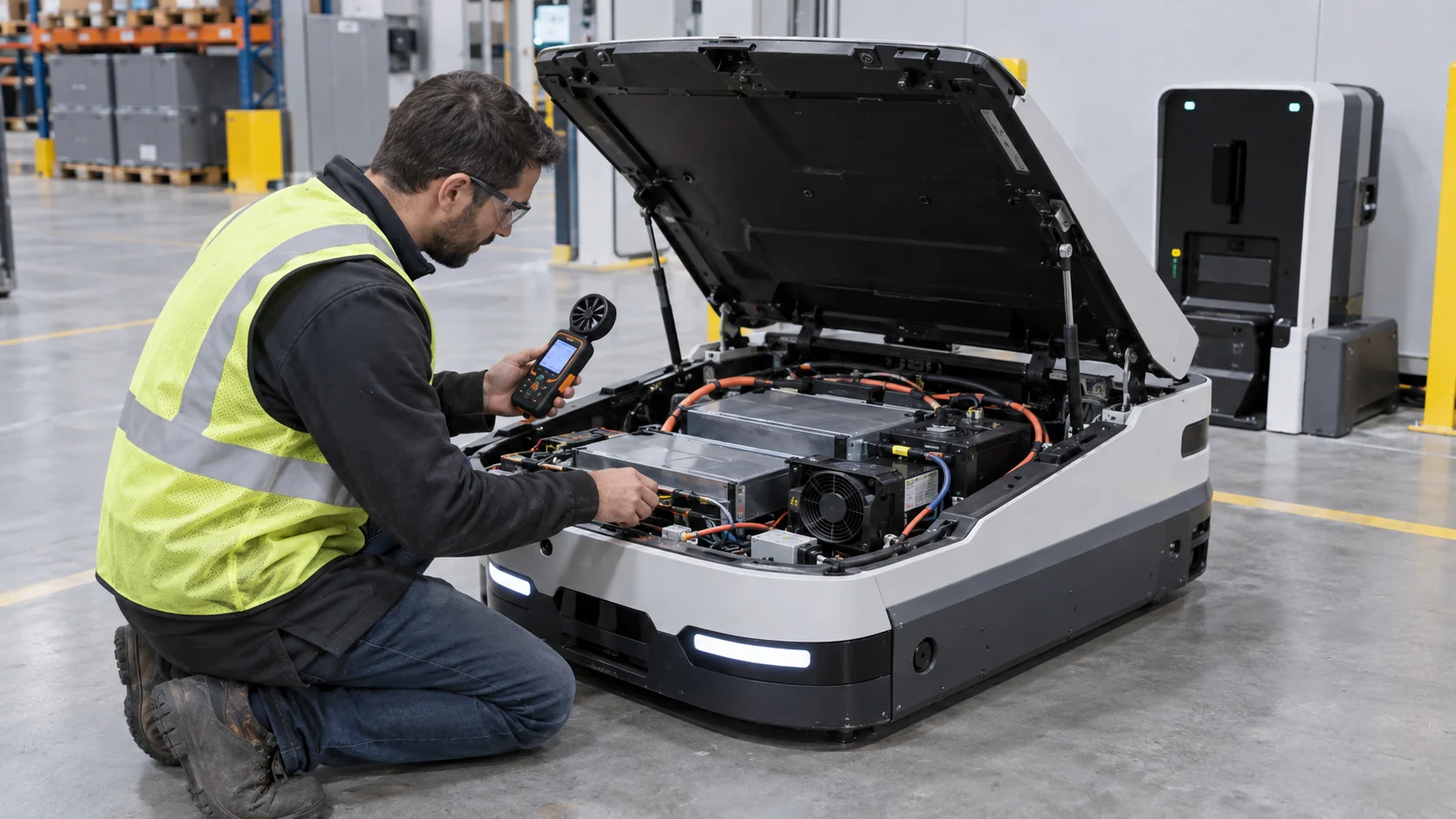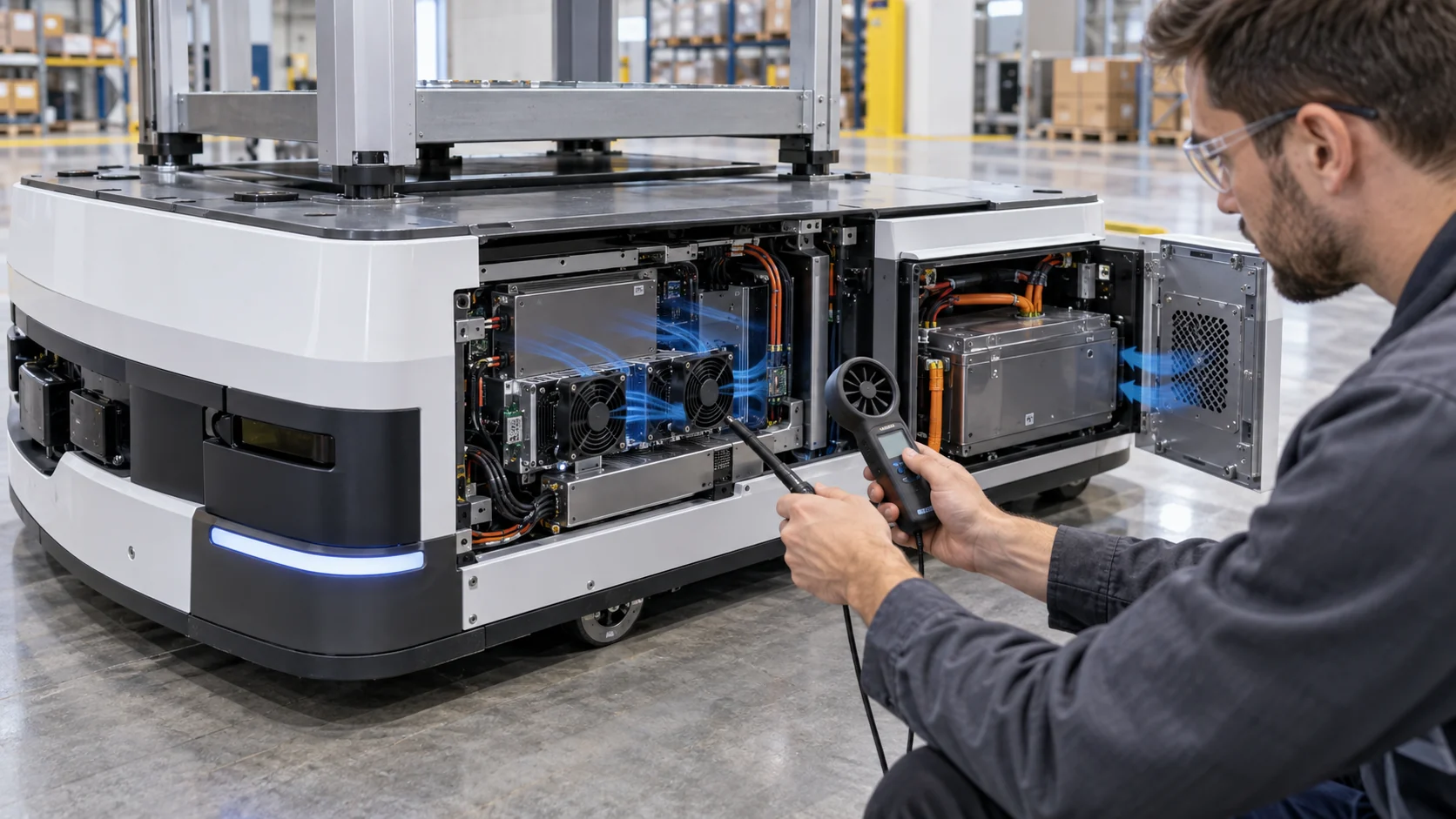
Robot Cooling Is a Motion-Duty Problem, Not Only a Cabinet-Temperature Problem
A controller cabinet may look comfortable at idle and still approach its thermal limit during repeated acceleration, deceleration and high RMS servo current.
Industrial robots and motion systems generate heat in servo drives, braking resistors, power supplies, DC links, network modules and control electronics. The heat load follows the motion profile rather than staying constant. A cabinet that passes a short idle test can therefore fail during a long pick-and-place cycle, a high-speed welding path or a repeated high-acceleration move sequence.
The cooling fan also works in a difficult environment. The cabinet may be near coolant mist, oil, dust, metal particles, packaging fibres or a washdown zone. A filter protects the electronics but adds pressure. Vibration from the machine frame can stress the fan bearing, bracket, connector and solder joints. A higher IP enclosure can reduce contamination while making heat removal more difficult.
This guide connects motion duty, installed pressure, filter loading, vibration, IP boundaries, control feedback and maintenance evidence. It is a fan and air-side engineering framework, not a replacement for the robot OEM's safety, electrical, EMC or machine-protection requirements.
Convert the Motion Profile Into a Thermal Test
The fan should be selected against the heat produced by the actual robot program, not only the controller nameplate.
List the servo drives, power supplies, braking components, transformers, network devices and other heat sources in the cabinet. Obtain loss data at idle, nominal production and the highest credible motion state. If the robot has a short high-current event followed by a long dwell, record both the peak and the average because the cabinet thermal mass and fan response see different time scales.
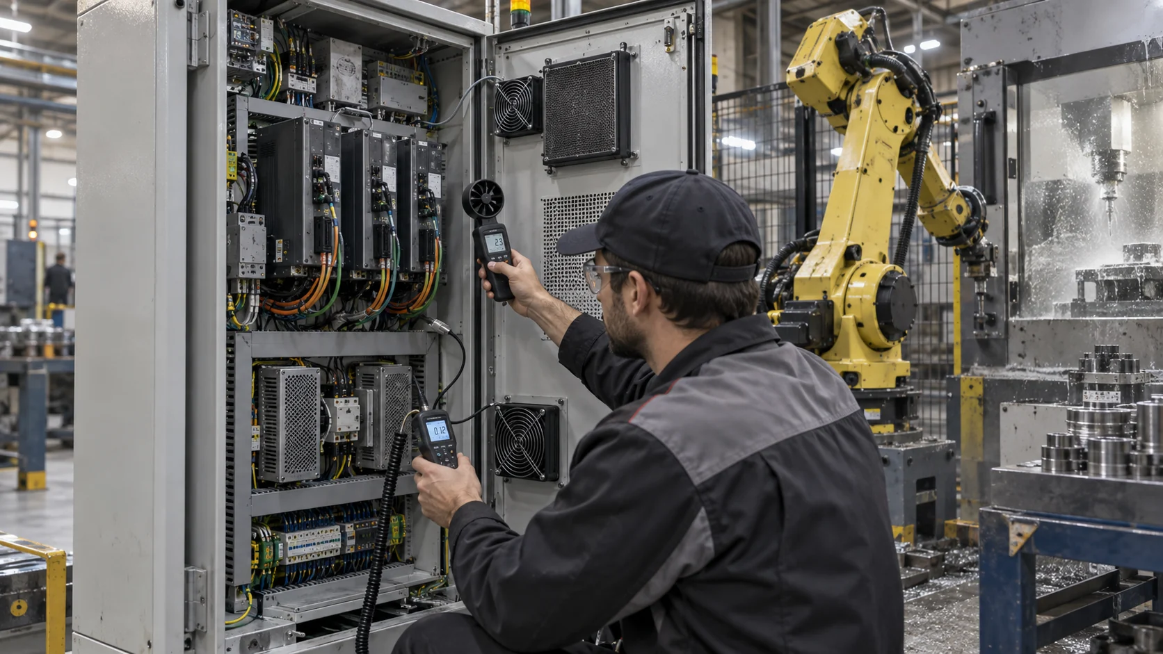
Use a repeatable motion or electronic load profile. Record cabinet inlet temperature, internal hot-spot temperature, exhaust temperature, fan command, current, speed feedback and machine state. A thermographic image can locate a hot component, but it does not replace a calibrated temperature point or airflow measurement.
For an illustrative estimate, three servo drives dissipate 180 W each during a demanding cycle, the power supply adds 120 W and control electronics add 60 W. The air-side heat load is approximately 720 W. If the design allows a 10°C cabinet air rise, the required mass flow is about 720/(1,005 × 10) = 0.072 kg/s before accounting for pressure, leakage and control margin. The actual fan point must still be tested on the populated cabinet.
| Input | Record | Why it matters |
|---|---|---|
| Motion sequence | acceleration, dwell and cycle time | sets transient and average heat |
| Servo losses | drive loss versus RMS current | identifies the limiting component |
| Cabinet ambient | temperature, RH and nearby process heat | sets the inlet condition |
| Protection state | filter, door seals, heat exchanger and IP path | sets installed pressure and contamination risk |
| Fan control | voltage/PWM, FG/RD and alarm logic | sets the usable response and maintenance evidence |
The Filter Is Part of the Thermal Design
A filter protects a controller from contamination, but its pressure drop changes the fan operating point over time.
Measure the filter in its actual frame, with the gasket, grille and door installed. Record clean pressure and the service-state pressure that corresponds to the planned maintenance action. Oil mist and fine metal dust can load a filter differently from ordinary office dust, so a visual inspection alone may not predict the pressure trend.
For a worked example, an intake grille contributes 18 Pa, a clean filter 32 Pa, internal drive passages 46 Pa and an exhaust louvre 24 Pa. The clean path is approximately 120 Pa. If the filter reaches 70 Pa in service, the path becomes about 158 Pa. A fan that delivers the target airflow at 120 Pa may no longer meet the requirement at 158 Pa, even if its tachometer still reports normal speed.
The maintenance threshold should be based on measured temperature and airflow evidence. A pressure switch can be useful, but confirm that the pressure taps are located across the filter rather than across an unintended bypass. If the controller relies on fan RPM only, add a thermal-spread or differential-pressure signal so that gradual degradation is visible before a servo over-temperature alarm.
Interactive: Watch the Cabinet Air Path Under Motion Load
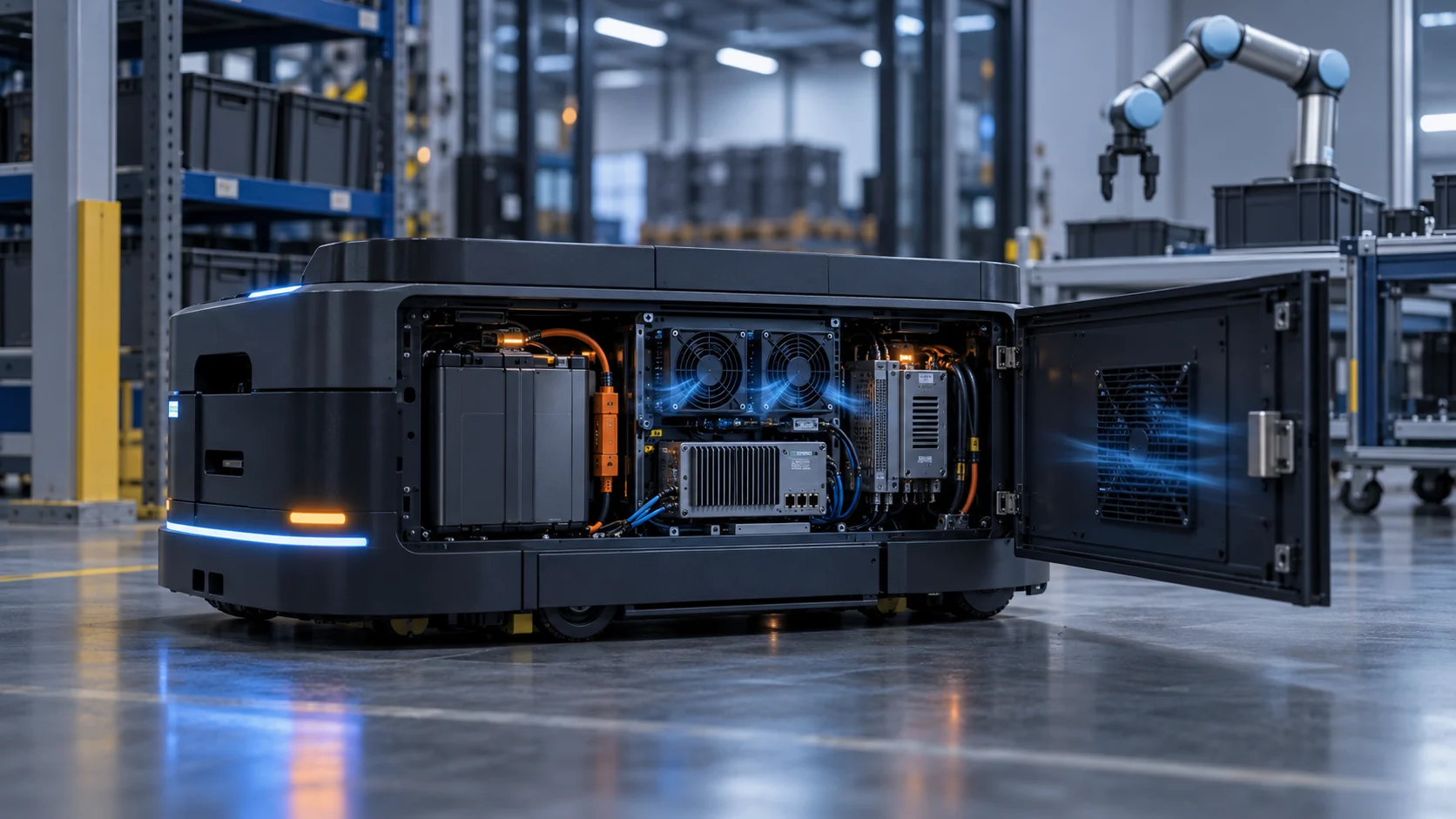
The schematic separates the drive heat source, filtered inlet and exhaust path, then shows how vibration and a loaded filter reduce the margin.
Use the visual to create three test states: idle or low motion, representative production cycle and peak-motion cycle. Add clean and loaded filter conditions, then repeat the same temperature and airflow measurements. If the fan is mounted on a vibrating panel, add a vibration measurement at the frame and bracket so that the thermal result is not separated from the mechanical environment.
A fan can move air at the outlet while the cabinet internal path remains poorly distributed. Check whether air reaches the drive heat sinks, whether cables block the inlet, whether hot air recirculates at the top and whether the exhaust has enough clearance. If a baffle or heat exchanger is added, measure the pressure change and verify the new operating point.
The animation is not a CFD result or a robot-specific thermal limit. It is a commissioning aid that makes the combined thermal, contamination and mechanical questions visible.

Vibration Changes the Fan Reliability Requirement
A fan that is reliable on a bench may experience a different duty when mounted to a robot cell or controller cabinet near moving machinery.
Define the vibration environment at the fan mount: frequency range, acceleration, axes, duration, shock events and whether the cabinet is mounted on the floor, machine frame or robot base. Check the bracket stiffness, fasteners, fan frame, guard, connector and cable strain relief. A loose guard or cable can create noise and secondary vibration even when the motor is healthy.
Select the bearing and mounting construction for the actual duty cycle. Ball-bearing designs are often preferred for vibration-prone industrial environments, but bearing choice alone does not prove the assembly will survive. The fan must be evaluated with the bracket, grille and connector installed, and the temperature must be included because lubricant and material behavior change with heat.
Trend speed, current, noise and vibration during the motion program. A gradual increase in noise or a fall in speed at the same command can indicate bearing wear, imbalance, a loose mount or contamination. Use FG or tachometer feedback as evidence, not as a substitute for mechanical inspection.
IP Protection and Airflow Are a Trade-Off
A higher enclosure protection level can reduce contamination but increase thermal resistance and maintenance complexity.
The completed cabinet determines the effective protection. Doors, seals, cable entries, fan cut-outs, filters, louvres and service covers all contribute. An IP-rated fan mounted in a poorly sealed cut-out does not make the cabinet IP-rated. Conversely, a sealed enclosure may require a heat exchanger or closed-loop cooling path instead of direct ambient air.
Review the process environment: coolant, oil mist, welding smoke, abrasive dust, metal chips, cleaning chemicals, humidity and condensation. Specify whether the fan sees filtered air or direct contamination. Check drainage and orientation so that water does not collect around the fan, connector or filter frame.
For robot arms or cobot joints, the mechanical and environmental requirements differ from a floor-mounted controller cabinet. A compact fan mounted on a moving assembly sees repeated acceleration, limited space and possible exposure to washdown. Do not transfer a cabinet fan specification to a robot-mounted module without checking vibration, cable flex and sealing.
Control Fan Speed From Temperature Without Losing Fault Visibility
PWM or EC control can reduce noise and energy during low motion, but the controller must still identify a blocked path or failed fan.
Use a temperature or power signal from the limiting drive zone as feedback, with machine state or servo RMS current as a feed-forward input. Validate the minimum stable duty, startup, restart, FG feedback, RD or locked-rotor alarm and behavior when a sensor is disconnected. A fixed maximum speed can mask poor airflow distribution and increase bearing wear, while a sensor placed near the fan can make the controller reduce speed before the far drive is protected.
For an illustrative energy comparison, two 24 V fans drawing 0.24 A each use 11.5 W at full command. If the motion controller holds them at 0.12 A for 60% of a 16-hour production day and 0.24 A for the remaining 40%, the estimated daily fan input is about 132 Wh. The machine cycle, cabinet temperature and drive life must be checked before claiming that lower fan speed is beneficial.
When the fan reaches maximum command but the cabinet remains hot, the system should distinguish high ambient, filter pressure, fan failure, blocked airflow and excessive drive loss. Clear diagnostics reduce unnecessary fan replacement and shorten downtime.
An Anonymous Customer Example: Servo Drive Alarm During a High-Acceleration Cycle
A European automation integrator used a custom fan sample after a robot controller passed idle testing but alarmed during a repeated high-speed production program.
The controller cabinet operated normally during commissioning and low-speed moves. During a long production sequence with repeated acceleration and braking, one servo-drive zone reached its temperature alarm earlier than expected. The fan was spinning and the cabinet filter appeared visually acceptable, so the first suspicion was a drive fault rather than a cooling-path problem.
MEGA Tech reviewed the motion profile, drive loss, fan voltage, PWM command, FG signal, filter frame, internal cable routing and exhaust clearance. The team mapped temperatures near the top, middle and bottom of the drive stack and measured pressure before and after the filter. A prototype fan with a revised pressure-flow point and a modified baffle was compared with the existing fan at the same motion cycle.
The test showed that the original fan moved adequate air in the open cabinet but lost useful flow through the loaded filter and narrow internal passage. The top drive zone also received less flow because a cable bundle redirected the path. The revised sample and baffle improved the installed distribution, while the customer added a filter-pressure inspection and retained the drive-temperature alarm as a protective limit.
This is an anonymized engineering scenario, not a published customer performance claim. The transferable lesson is to reproduce the machine duty cycle and inspect the complete installed path before replacing a servo drive or selecting a larger fan.
| Test state | Measurements | Decision |
|---|---|---|
| Idle / low motion | cabinet temperature, fan duty and noise | establish the low-load baseline |
| Production cycle | drive temperatures, airflow and pressure | find the limiting zone |
| Peak acceleration | temperature response and vibration | check transient thermal and mechanical margin |
| Loaded filter | filter DP, fan current and drive temperature | define service threshold |
| Fan fault or sensor fault | alarm, fallback and machine response | confirm controlled protection |
Where MEGA Tech Fits In
We help robotics and automation teams develop fan samples around the controller heat load, installed pressure, vibration and protection requirement.
MEGA Tech can review custom axial fans, compact blowers and fan modules for robot controller cabinets, servo-drive enclosures, vision processors, motion-control hubs and compact cobot electronics. The review can include P-Q behavior, filter loading, PWM or voltage control, FG/RD feedback, bearing selection, vibration, IP and corrosion exposure, connector and cable exit, noise, temperature and small-batch sampling.
For a first review, provide the cabinet layout, drive and power loss, robot motion cycle, ambient and process environment, filter and grille data, voltage, control signal, feedback requirement, vibration or mounting information, noise target and expected quantity. A thermal image or alarm log during the real production cycle is more useful than a nameplate power value alone.
We also support cost-competitive replacements for Sanyo Denki, SUNON, Delta, NMB or ebm-papst fans when the replacement is verified at the same pressure, mounting, voltage, feedback, vibration and environmental condition. A frame-size match is only the beginning; the production decision should follow the measured operating envelope.
Engineer FAQ: Robot Controller Cabinet Fan Selection
These questions connect fan selection to motion duty, contamination and machine availability.
Q: Can I size the fan from the controller nameplate power? A: Use the actual drive and power losses during the robot motion profile, including peak and average duty.
Q: Does a clean filter prove the cabinet will remain cool? A: No. Validate the defined service-state filter pressure and maintenance threshold.
Q: Is an IP-rated fan enough for an industrial robot cell? A: No. The complete cabinet, cut-out, connector, filter, seals and process environment must be evaluated.
Q: Why does a robot controller overheat while the fan still spins? A: Filter loading, poor distribution, blocked cables, high ambient, wrong fan direction or reduced fan performance can all coexist with normal RPM.
Q: What vibration information should be checked? A: Measure the fan mount and define frequency, acceleration, axes, shock, bracket and connector requirements for the machine.
Q: Should the fan run at maximum speed during every motion cycle? A: Not necessarily. Use validated PWM or EC control tied to the limiting thermal zone, with clear fault and over-temperature protection.
Q: Can MEGA Tech support small robot-controller samples? A: Yes. We can adjust fan parameters and interfaces, build samples and support pressure, thermal, vibration, noise and environmental validation before production.
Robot Controller Fan Review Checklist
Use this checklist before freezing the fan, filter, bracket, control curve or maintenance interval.
- Was the fan selected from the actual motion-duty heat load rather than nameplate power alone?
- Were top, middle and bottom drive zones measured during a representative cycle?
- Were grille, filter, cable routing, baffle and exhaust losses included?
- Was clean and service-state filter pressure tested?
- Were PWM/EC minimum duty, FG/RD feedback, startup and restart checked?
- Was the fan bracket, guard, connector and cable strain relief checked under vibration?
- Were dust, oil mist, coolant, metal particles, condensation and washdown considered?
- Were noise, vibration, bearing life, IP boundary and service access verified?
- Were fan, sensor and filter faults tested with controlled machine protection?
- Are measured values, estimates, OEM limits and machine-safety requirements clearly separated?