 01
Read the reference
Record the part number, frame, thickness, mounting, direction, connector, pinout, cable exit and installed conditions.
- Check
- what is known, and what still needs measurement?
 TECHCooling Solutions
Custom replacement cooling fan
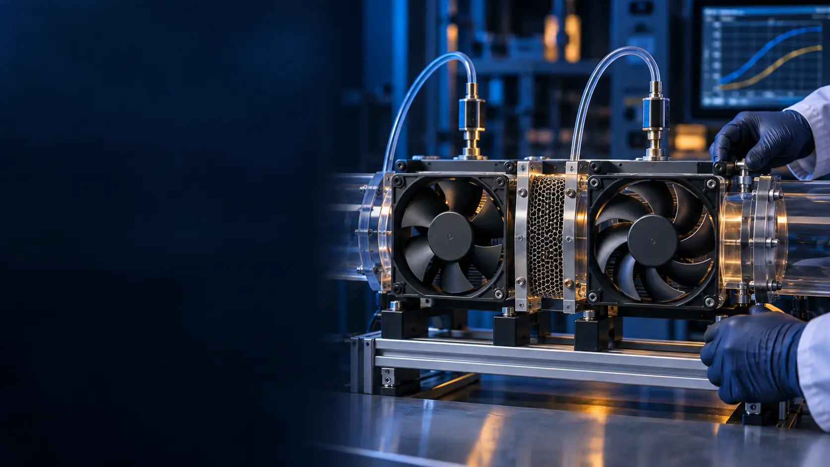
MEGA Tech develops custom replacement cooling fans by comparing the reference fan, air path, control interface and installed thermal result before a production decision.
Since 2008Shenzhen manufacturingISO 9001CE · RoHSSee how we build them →
Customization scope
Every dimension below is engineered around the installed duty — not picked from a catalogue.
How the work becomes evidence
The reference fan gives us a starting point, not a pass/fail answer. The candidate must work in the same restriction, voltage window and control system as the product.
01Record the part number, frame, thickness, mounting, direction, connector, pinout, cable exit and installed conditions.
 02
Compare airflow at the required static pressure, not free-air CFM. Include grille, filter, heat sink, duct and cable restrictions.
 03
Verify voltage window, startup, current, PWM command, FG/TACH, RD alarm, connector and fault timing.
 04
Run the candidate in the real assembly at normal and worst-case states, then freeze the accepted configuration.
Engineering evidence
Two fans can share a frame and nominal voltage while producing different airflow at the grille, heat sink or enclosure resistance. A free-air CFM headline cannot prove equivalence. The comparison point is where the fan curve meets the installed system curve.
Engineering evidence
Mechanical: frame, thickness, holes, direction, sealing, clearance and cable exit. Electrical: voltage tolerance, steady and start-up current, PWM convention, FG/TACH pulses, RD logic, connector and pinout. System: airflow and static pressure, protected temperature, noise spectrum, vibration, environment and life assumption.
Engineering evidence
An anonymised AI-server integrator needed an alternative without losing installed airflow, control behavior or fault visibility. The tray added grille, heat-sink and cable-path resistance that the catalogue free-air value did not show. The comparison used the populated tray, the same control points and logged pressure/airflow evidence, current, PWM, FG/RD, temperature and acoustics. The result was a documented engineering option, not a claim that every same-size fan is interchangeable.
Engineering evidence
The release record should name the installed operating point, pressure method, voltage range, control behavior, connector, mounting, acoustic position, temperature condition and life assumption. The product owner completes system-level safety, compliance and approval. MEGA Tech provides the fan-side sample and evidence needed for that decision.
A record an engineer can review
Use the same installed assembly for the reference and candidate. A structured record makes the result traceable when procurement, firmware and thermal teams review the change.
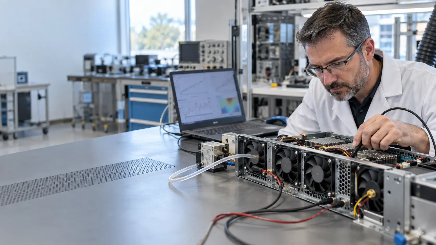
Part number, frame, thickness, mounting, airflow direction, connector, pinout and cable exit are recorded before a sample is selected.
Grille, filter, heatsink, duct and cable restrictions define the pressure path. Compare airflow at that installed duty, not at free air.
Check voltage range, start current, PWM response, FG/TACH or RD behavior, and whether the host controller reads the candidate correctly.
Repeat the comparison at the relevant temperature, supply tolerance, load state and service condition such as a loaded filter.
Keep the measured result, sample revision, acceptance rule and open risks together so the next build does not restart the investigation.
Two installed-air-path examples
These anonymised records are not universal replacement promises. Each begins with a physical assembly, a defined risk and evidence for the next design decision.
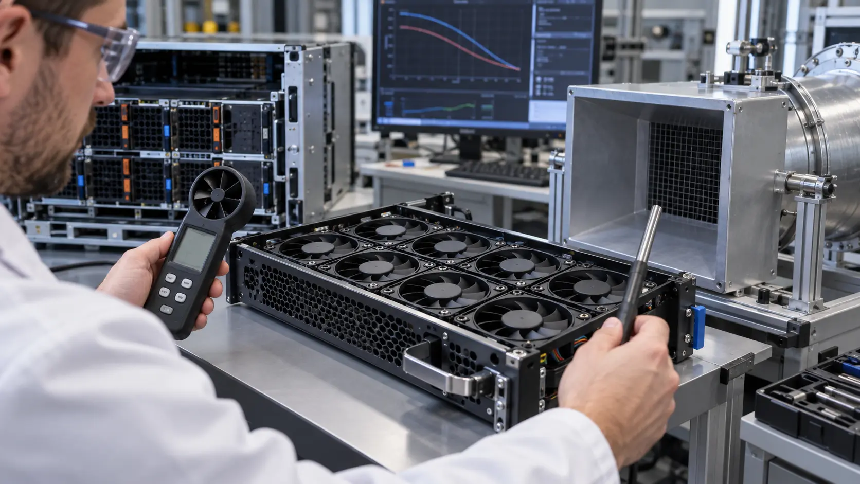
AI SERVER FAN TRAY
The tray changed the pressure path that a free-air catalogue value could not show. The review kept the same control points and logged pressure or airflow evidence, current, PWM, FG/RD, temperature and acoustics.
Read the server-tray case →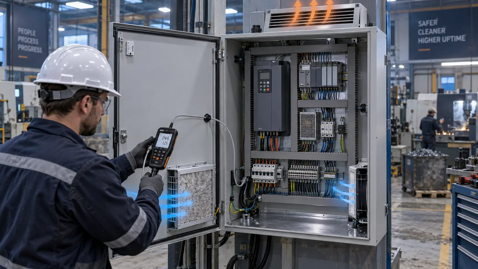
VFD / UPS CONTROL CABINET
The candidate had to meet the cabinet's installed pressure, control behavior and temperature duty with the intended filter state—notot merely fit the same cut-out.
Read the cabinet case →When the original datasheet is missing, we can start from the installed fan, enclosure details, photos and measured temperature or pressure points.
MEGA Tech reviews fan-side fit, interface and air-path constraints before the sample is judged in the customer's assembly.
The customer retains system safety, compliance and final product approval; we provide fan-side sample evidence for that decision.
Send the information you have
The reference fan gives us a starting point, not a pass/fail answer. The candidate must work in the same restriction, voltage window and control system as the product.
Send the information you have →Common questions
Yes. Prototype and small-batch builds run through our prototyping path before any volume commitment.
Lead time is quoted per project — it depends on frame tooling, interface work and the validation scope. Send the checklist above and we will reply with a project-specific schedule.
The six items in the checklist above, or the structured RFQ engineering inputs guide. Photos and the installed conditions are enough to begin.
Yes — connector, pinout, cable exit, PWM convention, FG/TACH pulses and RD logic are verified as part of interface matching before release.
MEGA Tech engineering review
Send the information you have: airflow and static pressure at that airflow, temperature and altitude basis, voltage tolerance, size, quantity, control interface, connector, noise target, environment and life assumption.