The Replacement Looked Right Until the Server Was Loaded
An anonymized AI server integrator needed a lower-cost fan-tray alternative without losing installed airflow, control behavior or fault visibility.
The candidate replacement matched the frame outline and voltage, but the first catalogue comparison was inconclusive. The server tray had a restrictive grille, heatsink path and cable-side obstruction. The fan that looked similar in free air did not automatically have the same operating point in the populated chassis.
MEGA Tech reviewed the tray, pressure path, current fan, PWM and FG/RD interface, acoustic target, thermal limit and production quantity. The customer identity and released acceptance values remain confidential. Illustrative calculations are labelled and are not customer test results.
The Engineering Hook: Same Size Is Not Same Performance
A fan replacement is an engineering comparison, not a logo swap.
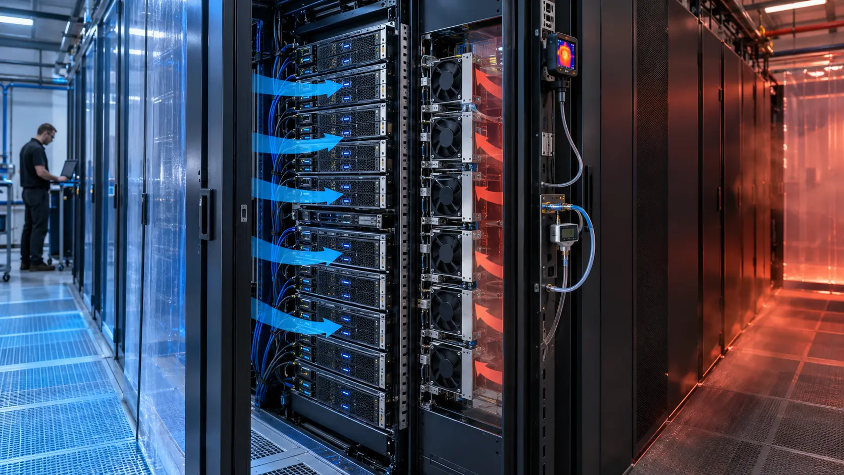
ASHRAE fan guidance treats pressure-versus-airflow performance as a laboratory characteristic that must be used with the installed operating point. In a server tray, the system curve includes the inlet grille, fan spacing, heatsinks, cable obstruction, outlet and chassis pressure. The candidate must be compared at that point.
The control interface is equally important. A four-wire PWM command, tach or FG output, rotor-lock or RD signal, start behavior and minimum stable speed can change the server firmware response. A replacement that moves air but reports the wrong feedback can still fail the product integration.
The integrator therefore asked for a sample with measurable P-Q data, electrical behavior, acoustic evidence and mechanical fit before discussing production cost.
The Problem in Operation: The Tray Added the Pressure That the Catalogue Did Not Show
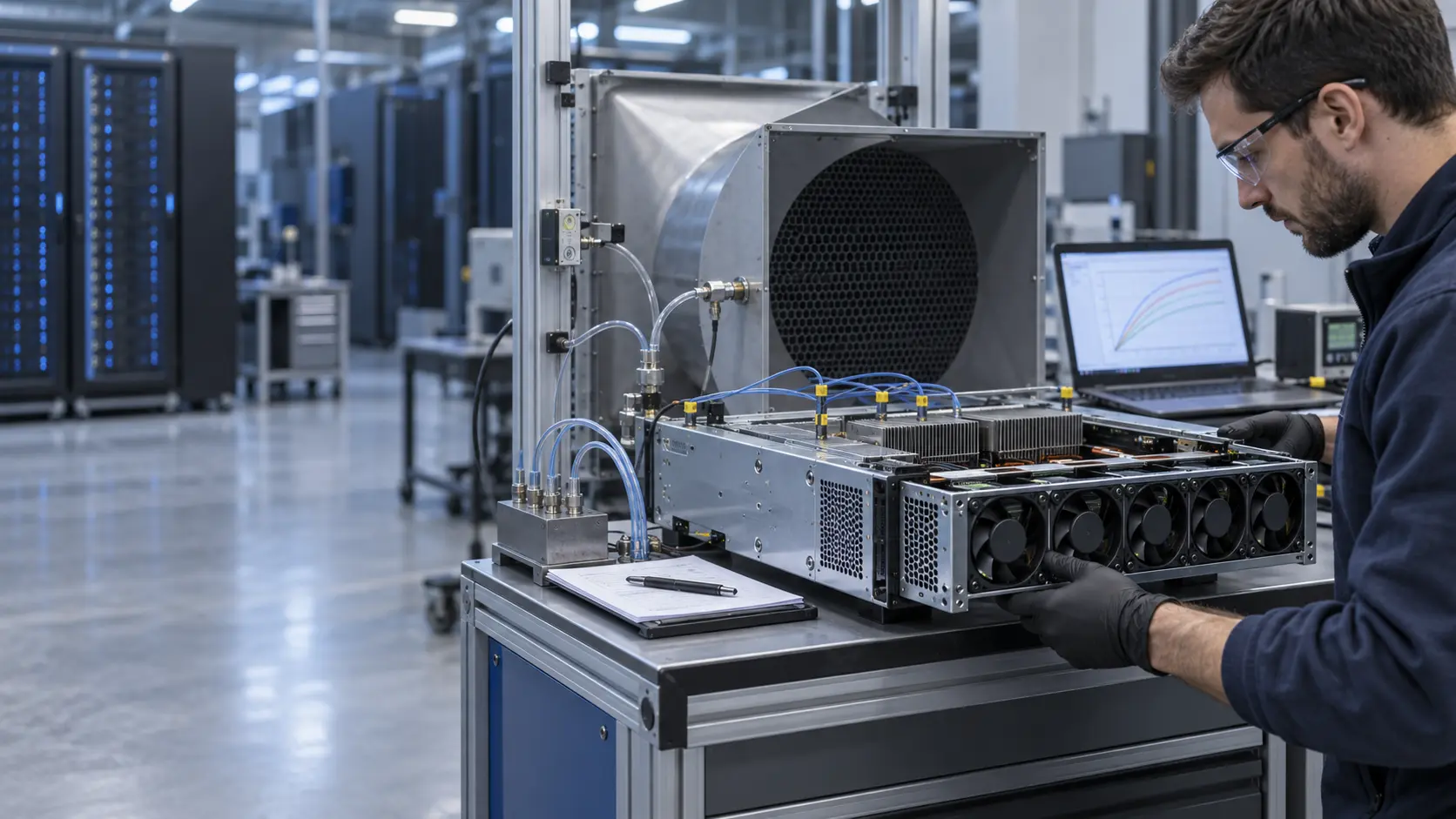
The original fan and candidate were screened with the server tray populated and the airflow path assembled.
The team measured airflow or a calibrated proxy, differential pressure, fan current, PWM duty, RPM or FG, RD response and the temperature at the limiting heatsink. The test included normal load, a high-load step, reduced command and one fan-fault state.
A simple system estimate used ΔP = k × Q² as a starting point, then replaced the estimate with measured tray points. The candidate was not accepted at maximum free-air CFM. It had to deliver the required flow at the populated tray resistance and leave control headroom.
Noise was recorded at the same thermal point. If the candidate was quieter only because it delivered less airflow, the result was rejected. The acoustic comparison also watched for tonal peaks caused by the grille or fan spacing.
Interactive: Watch the Candidate Move Along the Tray Curve
The animated schematic shows a free-air point, the installed tray operating point and a loaded-tray point after restriction increases.
The figure is qualitative, not a product curve. It demonstrates why a maximum CFM headline cannot prove equivalence. As resistance increases, the operating point moves to lower airflow unless the fan has sufficient pressure capability or the tray is redesigned.
The test sequence retained the same grille, heatsink path, cable condition, voltage, PWM command and sensor locations for both fans. This kept the comparison fair and made the result useful for procurement.

Sample 01: Freeze Mechanical and Electrical Compatibility
The first sample gate was more demanding than matching the envelope drawing.
The customer supplied the fan opening, thickness, mounting, connector, pinout, airflow direction, voltage tolerance, PWM convention, FG/RD expectation, start timing, minimum speed, acoustic limit and service access. The sample was checked for cable clearance, screw position, guard interaction and vibration transfer.
A simple electrical estimate was recorded. A 12 V fan drawing 1.8 A uses about 21.6 W at that point. Eight fans would be about 172.8 W before controller losses. These are illustrative values only; actual current, start current and server power limits control the release.
The candidate was not called equivalent until mechanical fit and signal behavior were both reproducible across repeated starts.
Sample 02: Compare at the Installed Operating Point
The P-Q comparison used the real tray resistance rather than a catalogue free-air value.
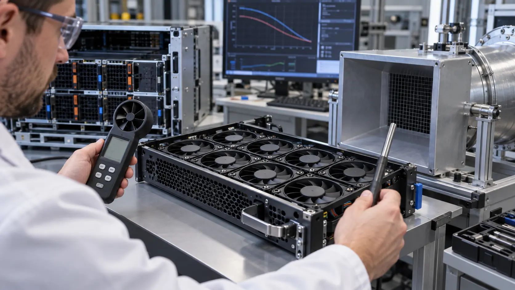
MEGA Tech reviewed axial and compact blower options according to pressure, airflow, voltage, PWM, FG/RD, noise, bearing and life requirements. The candidate was tested at the customer's control points and at the populated tray pressure.
The fan curve was compared with the tray curve and the limiting temperature. A candidate with a similar airflow at zero pressure could still underperform when the heatsink and grille were installed. A candidate with more pressure headroom could operate at a lower command, but only if the acoustic and power results remained acceptable.
The customer also checked supply variation, start response and locked-rotor or RD behavior so a fan fault would be visible to the server controller.
Sample 03: Validate Load Step, Fault and Long-Duty Behavior
A replacement sample was evaluated through the transitions that can expose a hidden mismatch.
The rack or server was run at steady load and a controlled power step. The log captured inlet temperature, heatsink temperature, fan command, feedback, current, pressure and acoustic level. The response delay was reviewed before setting the control thresholds.
One fan path was restricted or disabled where the tray design allowed it. Remaining fans were checked for reverse flow, pressure interaction and thermal recovery. The customer retained responsibility for firmware, server protection, DCIM and facility cooling; MEGA Tech supplied fan-side sample data.
Long-duty operation included repeated starts, reduced-speed operation and a hot ambient point. This exposed bearing, vibration and connector issues that a short bench demonstration could miss.
Validation Result: A Brand Alternative Became a Testable Engineering Option
The result was a documented comparison, not a claim that every same-size fan is interchangeable.
The release record included the installed P-Q point, pressure method, airflow or proxy, PWM/FG/RD behavior, current, acoustic position, voltage range, mechanical drawing, mounting, temperature condition and life assumption. The customer could compare future lots against the same evidence.
For procurement, the transferable lesson is simple: compare performance at the real tray resistance. MEGA Tech can reduce cost and provide custom samples, but the correct replacement is selected by operating condition and verified on the customer's unit.
How MEGA Tech Supports AI Server Fan Replacement
MEGA Tech develops and validates custom DC fan samples for server trays, racks and other restricted electronic air paths.
We can review compact axial fans and blowers, P-Q duty, grille and heatsink pressure, PWM and FG/RD signals, connector and lead-wire details, bearing and life targets, vibration, acoustic limits, voltage tolerance and small first-build quantities. We can also evaluate alternatives to Sanyo Denki, SUNON, Delta, NMB, ebm-papst and other installed brands when the operating point is defined.
Please provide heat load, airflow and static pressure at that airflow, temperature and altitude basis, fan size, voltage, quantity, control interface, connector, noise target, environment and life assumption. If data is incomplete, send the current part number, tray photos, grille details and measured temperature or pressure points.
Our scope is fan and air-path engineering, sample customization and comparative validation. We do not supply the customer's server firmware, DCIM/BMS, CRAH/CRAC, containment or facility safety design.
Engineer Questions About This Replacement Case
Use these questions before approving a lower-cost server fan replacement.
Q: Is the same frame size enough? A: No. Compare installed airflow, static pressure, control signals, noise, current, life and fault response.
Q: Can maximum CFM prove equivalence? A: No. The tray operating point is where the fan curve intersects the populated system curve.
Q: Does PWM compatibility prove the fans are interchangeable? A: No. Check polarity, frequency, duty range, FG/RD behavior, start and locked-rotor response.
Q: What should I send for a review? A: Send heat load, airflow and pressure, fan size, voltage, quantity, control, noise, environment and life target.
Q: Can MEGA Tech provide a sample? A: Yes. We can review the installed duty and support a sample comparison before production release.
Need a Server Fan Replacement Sample?
Send the current fan part number, tray photos, airflow and static-pressure target, voltage, control interface, noise limit and environment. MEGA Tech will review the installed operating point before recommending a sample.
Include the grille, heatsink and cable-path details plus any temperature, pressure, current or acoustic data available. This helps separate a fan mismatch from a tray, control, sensor or server-layout problem before the production BOM is locked.