One belt-driven fan is one point of failure
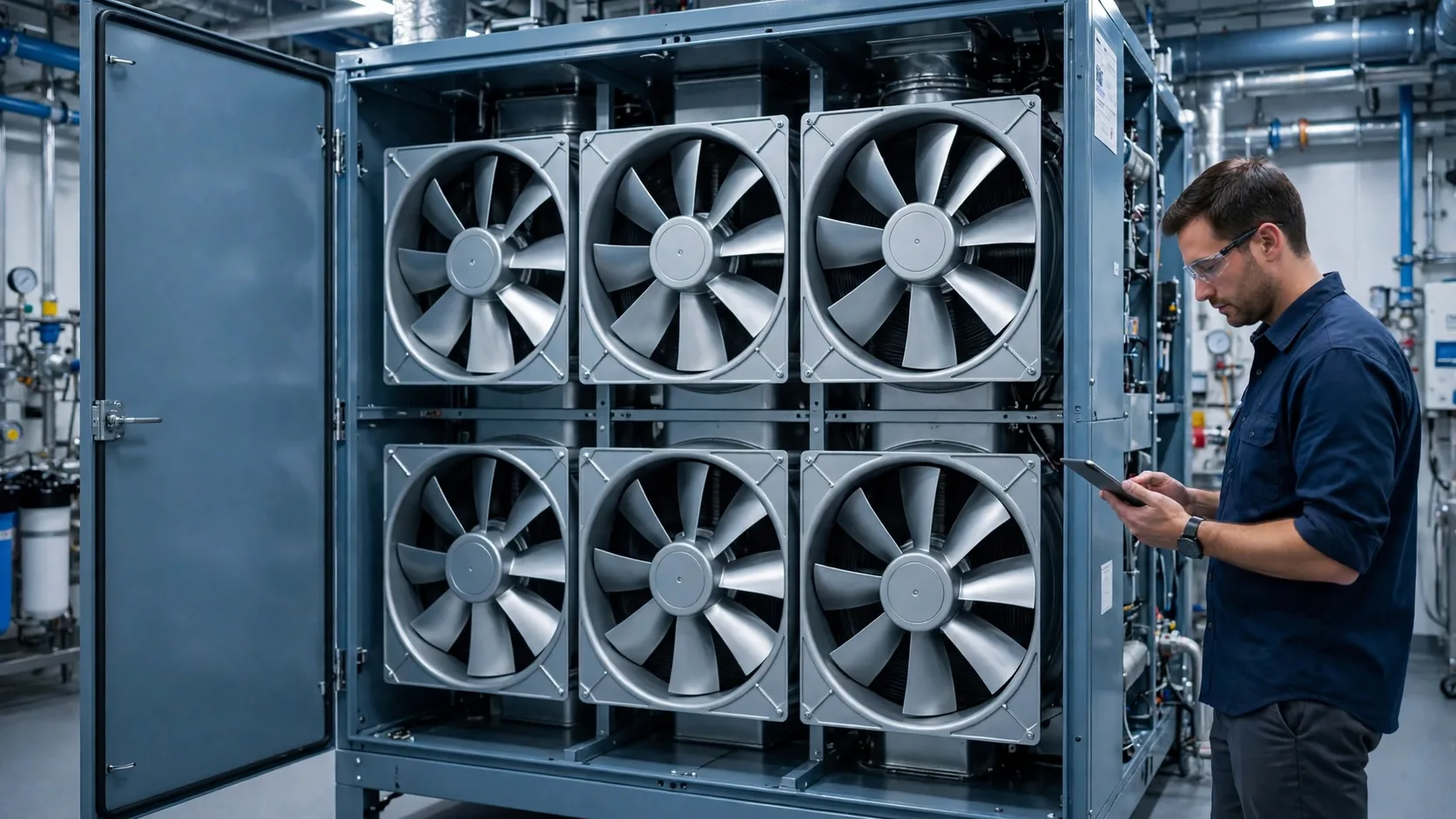
At COMPAMED 2026, ebm-papst put hospital air handling on the retrofit agenda: replace the single belt-driven blower inside an ageing AHU with a parallel wall of direct-drive EC centrifugal fans — a FanGrid — without replacing the cabinet. This guide turns that idea into selection checks a facility or HVAC engineer can run before signing anything.
The legacy arrangement is familiar in hospitals, data centers and commercial buildings: one large centrifugal fan, one AC induction motor, one belt set, moving all of the air for the whole air handling unit (AHU). It has three weaknesses that no maintenance plan removes. First, it is a single point of failure: a snapped belt or a failed bearing stops 100% of the airflow, and in a hospital that means the pressure cascade protecting operating suites and isolation rooms is gone within minutes. Second, the belt sheds rubber particles into the airstream as it wears — the opposite of what ISO 14644 cleanliness thinking wants upstream of the filters. Third, a belt-driven AC fan is at its worst exactly where an AHU spends its life: at partial load, where belt slip, fixed transmission losses and crude speed control waste energy for all 8,760 hours of the year.
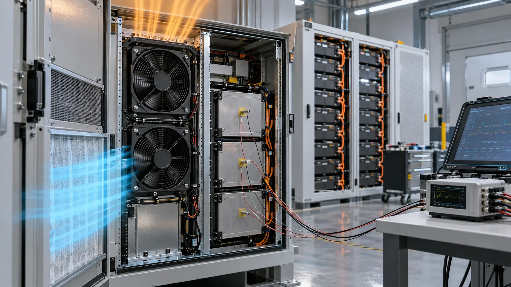
The fan wall answer, as presented in the COMPAMED 2026 retrofit material, is to split the duty across a parallel array of smaller direct-drive EC centrifugal modules inside the existing casing. Air distributes more evenly across the filter bank, redundancy is built in as N+1, and when one module faults, the rest speed up over the control bus and hold static pressure and airflow — no emergency shutdown, no lost cascade. None of that is automatic, though. It happens only if the array was sized, controlled and validated correctly, which is what the next sections check.
First decision: replace the blower, or convert to a fan wall?
A fan wall is not always the right scope. If the AHU casing leaks, the coils are fouled beyond cleaning, or the unit has less than five years of credible life left, replacing the whole AHU is the honest project and a new wall inside a dying cabinet is wasted money. The retrofit case is strongest when the cabinet, coils, dampers and casing have ten or more years left, the fan and motor are the weak link, and the building cannot tolerate a full AHU outage of days.
The second deciding factor is the downtime window. A like-for-like blower swap still needs the old fan out and the new one aligned, balanced and belted. A prefabricated fan wall, by contrast, is built and wired off-site and installed as an assembly — in the ebm-papst Munich Airport case below, each FanGrid went in within a day. If your window is one night or one weekend per AHU, the wall is often the lower-risk route, not the exotic one.
The third factor is whether redundancy is a stated requirement or a hope. A single fan can never offer N+1. If the rooms behind the AHU are operating suites, isolation rooms, a data hall or a production area that stops when ventilation stops, redundancy is a design input, not an upgrade — and only an array provides it.
Measure the installed duty before you touch the AHU
Every failed retrofit we see reviewed starts the same way: the array was sized from the old fan's nameplate instead of the installed duty. Nameplates describe free-air or test-rig conditions. The building has a duct system, loaded filters and a coil, and the fan works where its curve crosses that system resistance. Measure the real duty first — one working day per AHU — and write the numbers down as the baseline the retrofit will be judged against.
Split the total static pressure into a section-by-section budget. A mid-life hospital AHU at 30,000 m³/h might show 150 Pa across loaded filters, 180 Pa across the coils, 80 Pa across silencers and 60 Pa across dampers and louvres, with the remaining 330 Pa in duct and casing losses — 800 Pa in total. The numbers matter because the wall must hold the same total at the same flow, and because a budget exposes the real problem: if 300 of those 800 Pa sit across a filter bank that should drop 150 Pa, the first job is filters and cleaning, not fans.
| Measurement | How to take it | What a usable result looks like |
|---|---|---|
| Total airflow | Duct traverse or calibrated grille readings, dampers in normal running state | Design value in m³/h, within ±5% between two repeat runs |
| Total static pressure | Manometer across the AHU, then across each section in turn | A section-by-section budget in Pa that sums to the fan duty |
| Filter pressure drop | Across each filter bank at the measured flow | Actual Pa today, read against the maker's final pressure drop for change-out |
| Motor input power | True-power meter on the motor supply, 15-minute average at duty | Measured kW at the real duty — never the nameplate kW |
| Room pressure cascade | Differential pressure logger on the critical rooms, 24 hours | Differentials held through door cycles (positive rooms at +2.5 Pa or better) |
| Existing fan condition | Belt wear, bearing play, impeller fouling, photographs | A written keep-or-replace note for every rotating component |
Size the array with N+1 arithmetic
Array sizing is arithmetic, not catalogue browsing. Start from the measured duty — flow and total static pressure from the baseline — then choose the module count so that two conditions hold at once. In normal running, all modules share the duty at a part-load point where EC modules are efficient and quiet. With one module out, the remaining modules must still reach the full duty point on the maker's curve at no more than 90% of maximum speed, so there is headroom for filter loading and hot days.
Worked example at a 30,000 m³/h design duty. With five modules installed, each carries 6,000 m³/h in normal running; one fails, and the remaining four pick up 7,500 m³/h each — a 25% flow increase per module, at the same system pressure. Expect the survivors to run faster and louder for as long as the failed module is out: by the fan noise speed rule (about 50 × log10 of the speed ratio), a 1.25 speed ratio costs roughly +5 dB(A). That is the honest price of redundancy, and it is why the one-out condition is a test case in the pilot, not a brochure claim. The three standard configurations for this duty compare as follows.

| Configuration | Modules installed | Flow per module at design | Flow per module with one out | Selection note |
|---|---|---|---|---|
| 3 duty + 1 spare | 4 | 7,500 m³/h | 10,000 m³/h | +33% per module with one out: needs a large frame margin |
| 4 duty + 1 spare | 5 | 6,000 m³/h | 7,500 m³/h | +25%: the balanced default for most AHUs |
| 5 duty + 1 spare | 6 | 5,000 m³/h | 6,000 m³/h | +20%: most margin, most modules, wiring and cost |
Face velocity, filter pressure drop and air distribution
A single blower discharges into the casing at one point, and the filter bank downstream sees the result: a velocity profile with local peaks. On a large AHU it is common to measure local face velocities 1.5 to 2 times the mean near the discharge, while corners loaf. Filters load where the air actually goes, so part of the bank reaches its final pressure drop early while the rest is still clean — the averaged manometer reading looks acceptable while local bypass and uneven coil frosting or carryover have already started.
A fan wall discharges as a grid, so the velocity profile across the coil and filters evens out towards the design face velocity — for most AHU filter and coil sections, 2.0 to 2.5 m/s. A fine filter bank (ISO ePM1 class) typically starts at 90 to 140 Pa clean at rated face velocity and is changed out in the 250 to 450 Pa band, depending on the maker and the site's energy-versus-filter-cost balance. Even distribution does not repeal those numbers; it makes the whole bank arrive at them together, so the change-out interval becomes predictable and a pressure-drop alarm set at the final value means the whole bank, not one corner.
Two checks protect this benefit. First, blanking: any area of the wall frame not covered by a module — during staging, or permanently around a smaller array in a large casing — must be blanked off, or air short-circuits through the open area and the working modules unload. Second, backflow: a stopped module is an open hole through the wall. The array control and any backdraft arrangement must keep air from recirculating through the idle module, or the one-out arithmetic in the sizing section silently fails.
Part-load operation is where the energy is saved
AHUs in hospitals and data centers run 8,760 hours a year, and most of those hours are not at design flow. Night setback, mild weather and variable occupancy put a typical unit at 60 to 70% of design flow for long stretches. Fan physics rewards speed control directly: by the affinity laws, power falls with the cube of speed, so 70% flow costs about 34% of full-speed power in the ideal case, and 60% flow about 22%. A belt drive spends part of that gain before it starts — belt transmission losses of roughly 3 to 5%, slip that grows as the belt wears, and a motor running far from its efficient point.
This is the context for the savings figures attached to FanGrid retrofits: vendor benchmarking against legacy belt-driven hospital AHUs reports electrical efficiency gains of 15 to 35%, and the Munich Airport operator's energy team calculated about 252,000 kWh saved per year across two retrofitted systems. Treat both as attributed claims, not as your number: your saving is set by your hours at part load, your current belt and motor condition, and your electricity price — the pilot in section 8 measures it on your own AHU. As an order-of-magnitude check only: a fan drawing 15 kW at duty that saves 20% across 8,760 hours avoids about 26,300 kWh a year. State your own assumptions the same way when you run the number.
Control is what turns part-load capability into part-load savings. The wall should be controlled as one machine: a single demand signal (duct static pressure or flow) distributed over the bus to every module, with even speed sharing in normal running. Individual modules idling at different speeds, or one module at full speed while others loaf, gives back the distribution and efficiency the array was bought for.
Plan the cutover as a planned shutdown
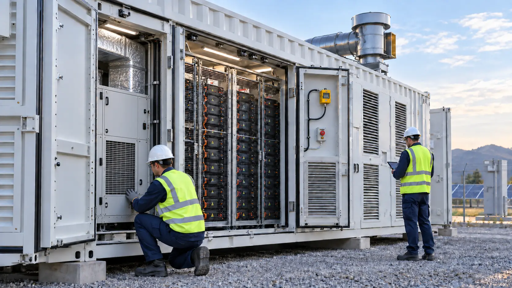
The reference case is worth copying in structure. In the ebm-papst Munich Airport retrofit, two air handling systems received four prefabricated FanGrid units between them — one on intake air, one on exhaust air per system, 34 RadiPac C centrifugal fans in total. Each FanGrid was installed within a day, and the whole project ran from late October to early December 2024 without the airport closing a terminal. Prefabrication is what made the window short: frames, modules and wiring arrived as assemblies, not as parts.
Your cutover plan needs the same shape, scaled to one AHU at a time:
- Survey and measure first: one working day per AHU for the baseline in the measurement section, including photographs of casing, coils and damper condition.
- Prefabricate off-site: wall frame, modules, blanking plates and wiring loom assembled and tested before the window opens.
- Cut over inside one night or weekend window per AHU; rooms that cannot pause get temporary ventilation or a scheduled downtime agreed with their owners.
- Recommission in the same shift: airflow traverse, room pressure cascade check, and a live alarm test at the building management system.
- Keep the removed motor and fan until the pilot trend is reviewed — on the first AHU, rollback stays physically possible.
Electrical, control and alarm integration checklist
More retrofit disappointments come from integration than from aerodynamics. The wall is a small electrical system in its own right — several drives, several supplies, one control intent — and it lands in a building that already has a BMS, an alarm philosophy and an electrical distribution designed for one big motor. Agree these points in writing before the order, not at commissioning:
- One breaker and one local isolator per module, so a failed module can be serviced safely while the rest of the wall keeps running.
- One control channel for the whole wall: bus control (for example Modbus) as primary, with a simple fallback signal such as 0-10 V or PWM that the existing BMS already speaks.
- Speed or status feedback from every module (bus status, or an FG tachometer signal on smaller drives): a stopped module must be visible at the BMS, never silent.
- BMS points as a contractual minimum: run status per module, fault per module, duct pressure or total flow, and filter pressure drop with its alarm threshold.
- Fault behaviour agreed in writing: on a module fault the remaining modules ramp automatically to hold the duty, the BMS raises the alarm within seconds, and no one has to visit the plant room to keep the rooms in pressure cascade.
Prove it on one pilot AHU first
Retrofit one AHU, trend it for a month, and only then price the fleet. The pilot converts every claim in this guide — the vendor's, the supplier's, ours — into your building's numbers. Choose the pilot unit deliberately: a mid-life AHU with a full baseline, representative duty, and rooms whose pressure cascade can be logged. Run the same measurements as the baseline, at the same damper state, and judge against pass conditions agreed before the work started.
| Pilot check | Method | Pass condition |
|---|---|---|
| Total airflow | Repeat the baseline traverse at the same damper state | Within ±5% of the pre-retrofit value |
| Static pressure | Manometer readings at the baseline test points | Duty pressure held within ±5% |
| Input power at duty | True-power meter at the same measured flow as baseline | Recorded kW at least 15% below baseline, or the gap explained in writing |
| One-fan-out test | Stop one module for 30 minutes at normal occupied load | Flow held within ±5%, room pressure differentials held, fault alarm raised at the BMS |
| Noise | Sound level meter 1 m from the casing at design duty | No more than +3 dB(A) against the baseline reading |
| Filter trend | Log filter pressure drop for 30 days after the retrofit | Rate of rise no faster than the pre-retrofit trend |
The honest boundary, and where MEGA Tech fits
A FanGrid is an engineered system, not a fan purchase. The EC plug fans, their integrated drives, the bus control, resonance management and the system warranty belong together, and they belong with the original maker or its authorised retrofit partners. MEGA Tech does not supply EC fan walls, large EC plug fans or AHU control systems, and nothing in this guide changes that: for the wall itself, use the original maker's channel, and hold them to the pilot conditions above.
MEGA Tech has manufactured cooling fans since 2008, from an office in Guangzhou and a factory in Shenzhen, certified to ISO 9001, with CE and RoHS documentation for its range. Our support follows the same five steps as our custom work: custom cooling fan development and manufacturing, fan selection, airflow-path review, sample validation and volume production. Around an AHU retrofit, that covers the DC axial positions the project touches — cooling fans inside variable-speed drive cabinets and control panels, BMS and controls enclosures, and the equipment fans in the imaging, laboratory and IT loads the AHU serves. Those are same-size DC replacements matched at the duty point, with samples validated in the real enclosure before any volume order.
To start that evaluation, send the fan you are replacing (a rating-plate photo is enough), the airflow and the static pressure at that airflow, the supply voltage and its tolerance, the control interface (PWM command, FG feedback, connector and pinout), the mounting envelope, and the noise target. If the position turns out to be a room-level EC one, we will say so and point you at the original maker's channel rather than quote you the wrong fan.
Engineer FAQ
Q: Can we keep the existing AHU casing and coils? A: Usually yes — that is the point of the retrofit. The conditions are a casing that seals well enough to hold pressure, coils clean or cleanable to their design pressure drop, and dampers that still position correctly. The baseline survey answers all three; if the casing leaks badly, fix that first or the wall will faithfully pressurise the plant room instead of the duct.
Q: How many modules do we need? A: Work the N+1 arithmetic from the measured duty, not from the old fan's frame size. Modules installed = duty modules + 1 spare; check that with one module out, the rest reach the full duty point at no more than 90% of maximum speed on the maker's curve. For a 30,000 m³/h duty, five modules is the balanced default in the sizing table above.
Q: What happens at 3 a.m. when one module fails? A: The remaining modules ramp up automatically over the control bus and hold airflow and static pressure; the BMS raises the fault alarm within seconds; the rooms stay in pressure cascade. Because each module has its own breaker and isolator, the failed unit is swapped in a normal daytime visit while the wall keeps running — that is the operational difference from a belt failure, which is an emergency call-out and a stopped AHU.
Q: Will the retrofit really save 15 to 35% of fan energy? A: Those figures are vendor benchmarking against legacy belt-driven units, and the Munich Airport operator calculated about 252,000 kWh per year saved on two systems — attributed claims, both. Your figure depends on your part-load hours and your current belt and motor condition. The cube law is on your side, but the pilot measurement, not this guide, is what should go into your payback calculation.
Q: Can MEGA Tech supply the EC fan wall for our AHU? A: No — and any supplier of DC axial fans who says yes to that question is selling you a problem. EC fan walls are engineered systems from the original maker or its authorised partners. What MEGA Tech does supply is the DC side of the project: same-size replacement DC axial fans for drive cabinets, control panels and equipment loads, selected at the duty point and validated as samples in your enclosure.
Questions for a Design Review
Bring these answers, with measured values attached, before a fan wall retrofit is released beyond the pilot AHU.
- What is the measured duty today — total airflow, the section-by-section pressure budget, and motor input kW at that duty?
- Which array configuration keeps the one-fan-out duty point at or below 90% of maximum speed on the maker's curve?
- What is the cutover window per AHU, and which rooms need temporary ventilation or agreed downtime inside it?
- Which BMS points and alarms are in the contract: per-module fault, filter pressure drop threshold, duct pressure or total flow?
- What are the pilot pass conditions — flow, pressure, power, one-fan-out, noise, filter trend — and who signs them before the fleet order?
- For every DC axial position the project touches: what are the airflow, static pressure, voltage, control interface and mounting envelope for the replacement sample?