The operating problem: a welder is not a clean cabinet
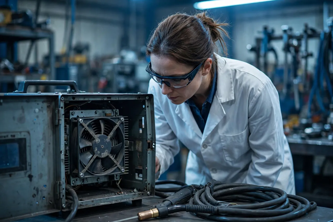
A welding power source combines a high thermal load with dust, metal spatter, cable movement and a changing duty cycle.
A welder can run quietly during a short bench demonstration and still overheat during a long job in a dusty workshop. The fan sees a grille, filter, cable bundle and internal heat sinks while the process alternates between idle, arc-on and cooling periods. Metal dust and spatter may collect near the inlet, while the outlet can recirculate warm air if the machine is placed close to a wall or another power source.
The engineering task is to define the installed operating point and the environmental challenge separately. Record the heat-producing duty, ambient basis, air path, filter condition, mounting orientation, noise target and service interval. A candidate should be judged by delivered airflow and temperature at that condition, not by a free-air number or by an assumed IP claim.

Translate arc duty into a thermal test plan
The useful load profile is usually a sequence rather than a single percentage. Define the idle period, arc-on period, pause, restart and any post-weld fan overrun. If the machine has several power levels, test the level that creates the highest internal heat and the level that creates the most demanding restart. The test record should identify whether the enclosure was open or closed and whether the torch and cable were installed as they are in use.
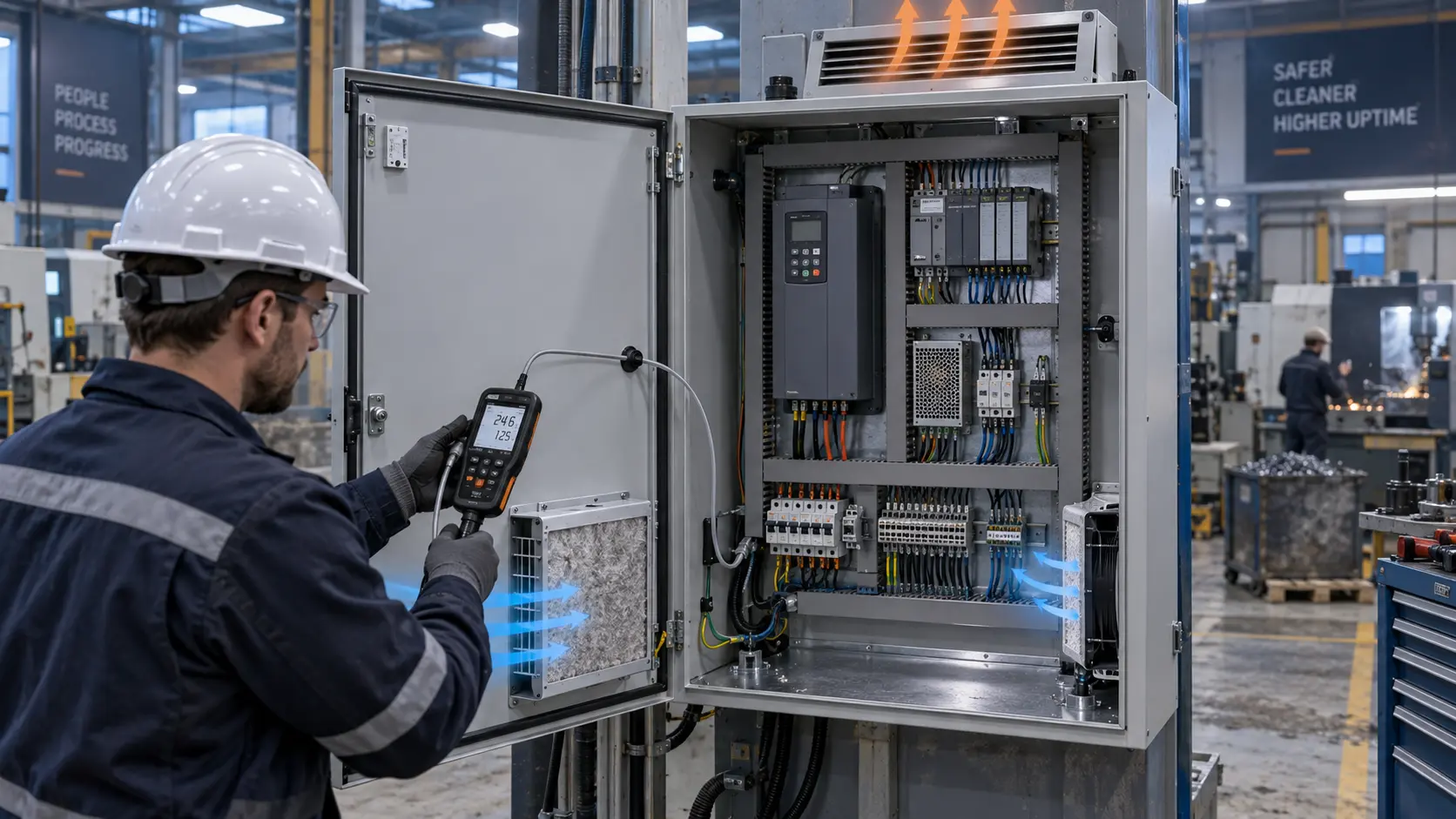
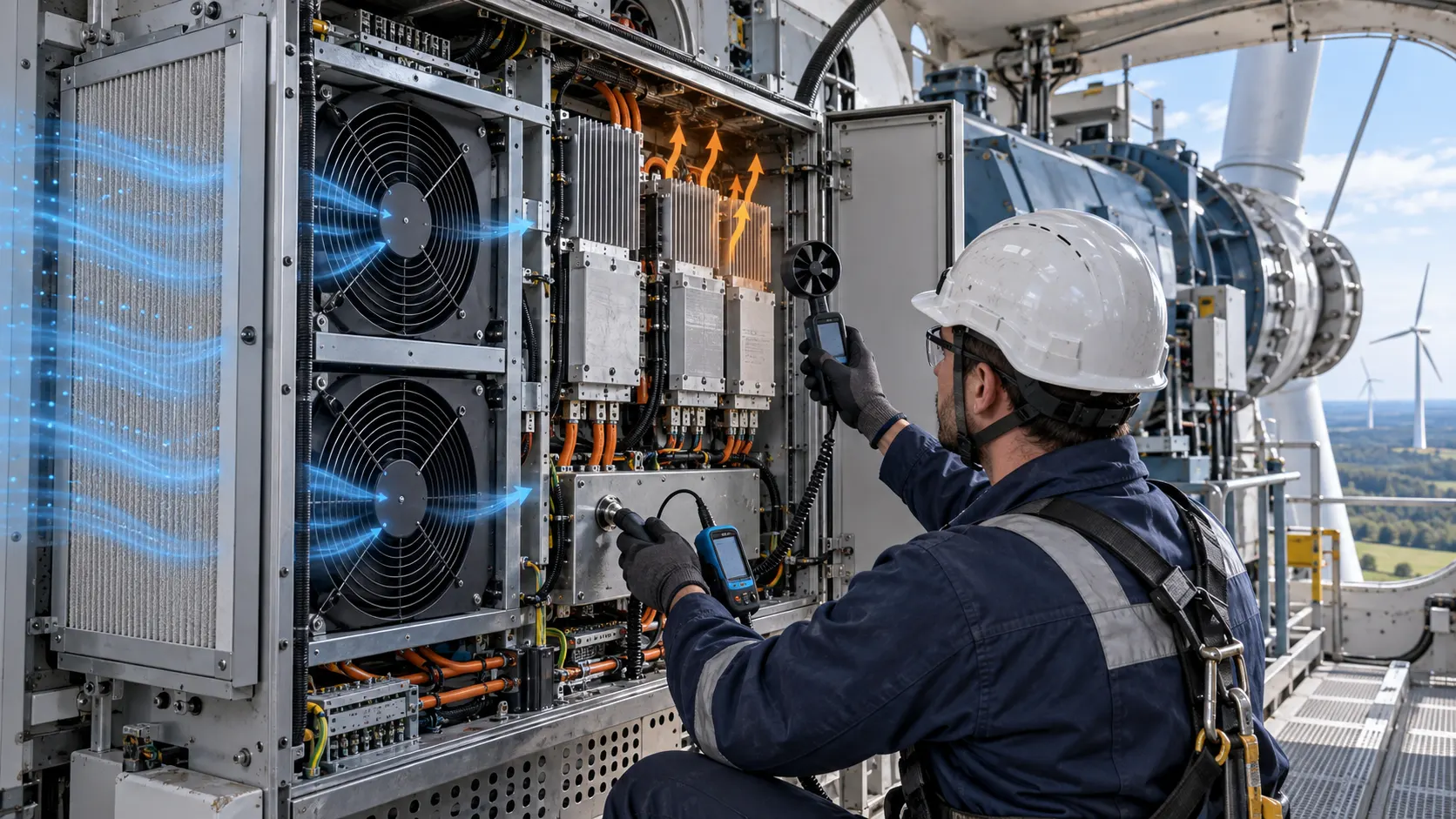
Use component temperatures and air temperatures to verify the path. A fan can deliver a strong outlet jet while a heat sink in a recirculation pocket remains hot. Map the inlet and outlet, inspect the pressure drop of the grille and filter, and repeat the test as the filter reaches its defined service condition. Where an exact heat load is not available, use the production power waveform or a controlled thermal substitute and label the method.
| State | Air-path condition | Evidence |
|---|---|---|
| Idle/start | Cold and warm start | Voltage, current, speed rise, alarm |
| Arc-on | Representative heat load | Heat-sink and outlet temperature, airflow/pressure |
| Pause/restart | Fan overrun and restart | Restart time, current and stable cooling |
| Dust/service | Filter or grille challenge | Pressure rise, airflow loss and service indication |
Manage dust and spatter without hiding pressure loss
A protective mesh or filter can keep large particles away from the impeller, but every restriction changes the fan operating point. Do not add a filter to a prototype and keep the original airflow claim. Measure the pressure at the clean and service conditions and define the point at which the machine needs cleaning. If spatter can reach the inlet, review the physical shield, airflow direction and access for inspection rather than relying on an unverified material label.
The fan frame, connector and cable route should be inspected after the environmental test. Dust can increase imbalance; spatter can obstruct a grille; a cable can move into the fan during transport or vibration. The supplier can discuss the fan-side operating envelope and sample construction, while the equipment designer owns the enclosure, extraction and protection decisions. Avoid writing a protection rating unless the exact product documentation supports it.
Select by pressure-flow behavior and service access
A short open path may suit an axial fan, while a power module with a narrow duct, heat-sink stack or filter may need a pressure-oriented axial design or a centrifugal blower. Compare candidates at the machine’s installed pressure and include the restriction increase caused by service loading. The fan should have a practical path to move air through the heat sink, not simply a high free-air rating.
Use the airflow and static-pressure curves method and make the system curve visible to the mechanical and electrical teams. Check whether the fan outlet jet reaches the heat sink, whether warm air returns to the inlet and whether the mounting transmits tonal noise. The fan noise and resonance guide can help separate airflow noise from bearing or structural noise during the sample review.
Test control, feedback and loss of cooling
If the welder uses PWM, FG or RD, validate the exact interface with the production controller. Test start, low duty, high duty, lost command, feedback loss and restart after a thermal pause. A normal RPM signal does not prove that the loaded filter path is delivering useful airflow. Pair the signal with pressure, airflow and heat-sink temperature.
Define the safe action for a fan fault: alarm, power reduction, controlled stop or service instruction. The correct action depends on the equipment risk and cannot be invented from a fan datasheet. Record delay, retry and recovery behavior in the machine specification, and ensure the operator can distinguish a fan fault from a filter service condition.
Validate vibration, transport and mounting
Welding equipment is moved, placed on carts and exposed to cable pull and workshop vibration. Inspect the frame, fasteners, grommets and cable exit after transport-like movement and after the thermal duty. Check for impeller contact, bracket resonance and changes in noise. If the fan is mounted near a large heat sink, verify that the heat sink or guard cannot deflect into the fan under assembly load.
Use the actual mounting torque and gasket compression. A soft mount can reduce transmitted vibration but can also allow the fan to move relative to the duct. A rigid mount can preserve alignment but transmit tonal energy. The sample should be evaluated in the same mechanical envelope that will go into pilot build.
Build a repeatable pilot acceptance record
A pilot record should include the fan revision, voltage, command, current, RPM/feedback, pressure or airflow, ambient temperature, heat-sink temperature, noise method, filter state and duty-cycle trace. Include photos or drawing references for the inlet, outlet, guard, cable route and mounting. If a result is inferred rather than directly measured, identify the inference and the next test needed.
Repeat the critical points after any change to the fan, filter, grille, guard, heat sink, controller or enclosure. This avoids accepting a quiet sample that no longer has the required pressure margin. It also gives procurement a clear basis for asking a supplier for a sample without promising a performance value before the operating point is reviewed.
How MEGA Tech can support the review
MEGA Tech supports custom DC, EC and backward-curved centrifugal fan development around the customer’s installed operating point. The useful input is the welding duty cycle, heat-source temperatures, dust/spatter exposure, filter or grille, mounting envelope, voltage and feedback requirements, not a part number alone. Share airflow and static pressure at that airflow, temperature and altitude basis, voltage tolerance, control interface, connector, envelope, noise target and life assumption. Samples should be evaluated in the representative air path before a production decision.
The boundary is important: MEGA Tech supplies and validates fan-side hardware and does not supply coils, liquid loops, controllers, cabinet safety design or emergency ventilation. A supplier discussion can start with the fan selection guide, the MEGA Tech products catalogue or contact MEGA Tech with the required operating conditions.
Engineer FAQ
Q: Should a welder fan run at full speed all the time? A: Not automatically. The control strategy should balance heat, pressure, noise, power and the actual duty cycle, with a defined overrun if needed.
Q: Does a mesh guard eliminate the need for pressure testing? A: No. A guard and filter still create pressure loss and can load with dust or spatter.
Q: Can normal RPM prove a welder is cooled? A: No. Verify installed airflow or pressure and the heat-sink temperature.
Q: What should be checked after transport? A: Clearance, mounting torque, cable route, fan noise, restart and the installed operating point.
Q: Who owns the alarm and power-reduction action? A: The welding-equipment designer owns system protection; the supplier provides fan-side evidence and sample support.
Questions for a Design Review
- What arc-on and post-weld duty sequence represents the highest thermal case?
- Which dust, spatter, filter and service conditions must be reproduced?
- Where are pressure and temperature measured, and what does each prove?
- What feedback and fault action does the controller require?
- Can outlet air recirculate into the inlet in the customer installation?
- Which changes trigger a new sample test before pilot production?
Separate the process environment from the fan qualification
Welding produces a process environment that may include smoke, metal dust, spatter, heat and cable movement. A fan qualification should state which of those were represented and which belong to the equipment extraction or enclosure design. A short exposure test can show whether a guard or filter remains functional; it does not automatically establish a universal protection class. Keep the supplier fan evidence and the machine environmental risk assessment as linked but separate records.
The service instruction should identify the visible signs that require inspection: rising pressure, falling airflow, unusual sound, an alarm, a blocked grille or a temperature trend. Define the safe action and the evidence needed to return to operation. If the machine is used in different workshops, review whether dust and spatter exposure changes the filter service interval. The fan can be selected for the pressure requirement, but the service plan determines whether that pressure remains available.
Compare samples at the same weld and air-path sequence
When two fans are compared, use the same welding waveform, torch cable arrangement, enclosure panels, filter state, mounting torque, voltage and measurement locations. Run the sequence long enough to capture the highest thermal state and include the pause or overrun that follows the arc. Record the time history rather than only the peak value. This distinguishes a fan with a different transient response from a fan that simply has a higher steady-state speed.
If the fan uses feedback, record the command and signal with the thermal trace. If it is a two-wire fan, record connector voltage, current and speed by the same method. Check the outlet for recirculation and the inlet for bypass. A sample that looks better in free air may underperform once the filter and heat sink are installed. The comparison must be made at the same operating point.
Define pilot-release evidence without inventing customer results
For an anonymised case, report the problem and method honestly: the equipment team observed a thermal or acoustic risk, the air path and duty were defined, samples were tested under representative conditions, and the release decision depended on the agreed acceptance record. Do not convert a test method into a claimed customer result. If measured values are not available, state the verification method and the pass/fail criterion the project should use.
At pilot release, freeze the fan revision, filter and grille, controller behavior, harness, mounting and service condition. A later change to any of these can move the pressure-flow point or change the environmental exposure. Keep a sample for reference and repeat the critical thermal, signal and noise checks when production or supplier changes are proposed.
Use a maintenance trend to protect the operating point
A filter or grille does not fail only when it is visibly blocked. Pressure and temperature trends can show that the system is losing margin before an alarm appears. Record a baseline after a clean service, then define which trend or threshold calls for inspection. If the machine operates in several environments, retain the exposure and service history with the trend so a workshop change is not mistaken for a fan change.
A trend is useful only when the measurement is repeatable. Use the same pressure tap, temperature location, fan command and operating state. If the controller has FG or RD, save the signal with the trend but do not treat it as a substitute for airflow evidence. This approach helps the service team clean or replace the correct part and gives engineering a stronger basis for a future filter or fan redesign.
Record the operator-facing acceptance result
A welding machine is accepted by people who need to know whether it is ready for work, not only by the engineer who ran the test. Write the service indication in plain language, show the normal fan state, identify the filter or grille check and state when the machine must be taken out of service. Include the measured evidence behind the instruction so the operator is not asked to judge airflow from sound alone.
During pilot use, compare the service observation with the engineering record. If the fan becomes louder, the pressure rises, or the heat-sink temperature drifts at the same duty, capture the environment and sequence before changing parts. This closes the loop between the sample validation and the field condition without claiming a result that was not measured.
Welder release note for the next build
Name the approved environmental fixture and service condition in the next build note. That detail lets the team repeat the dust, spatter and duty-cycle evidence when the enclosure or filter changes. Include the arc-on sequence, fan command, connector voltage, pressure or airflow method, heat-sink sensor and operator-facing alarm. If the machine is used in a different workshop, record the environmental difference before interpreting a trend as a fan failure.
Welder acceptance summary
The acceptance summary should identify the tested fan, mounting, path, environmental challenge, duty sequence and the measured result or open verification method. It should not turn a project-specific sample into a universal certification statement.