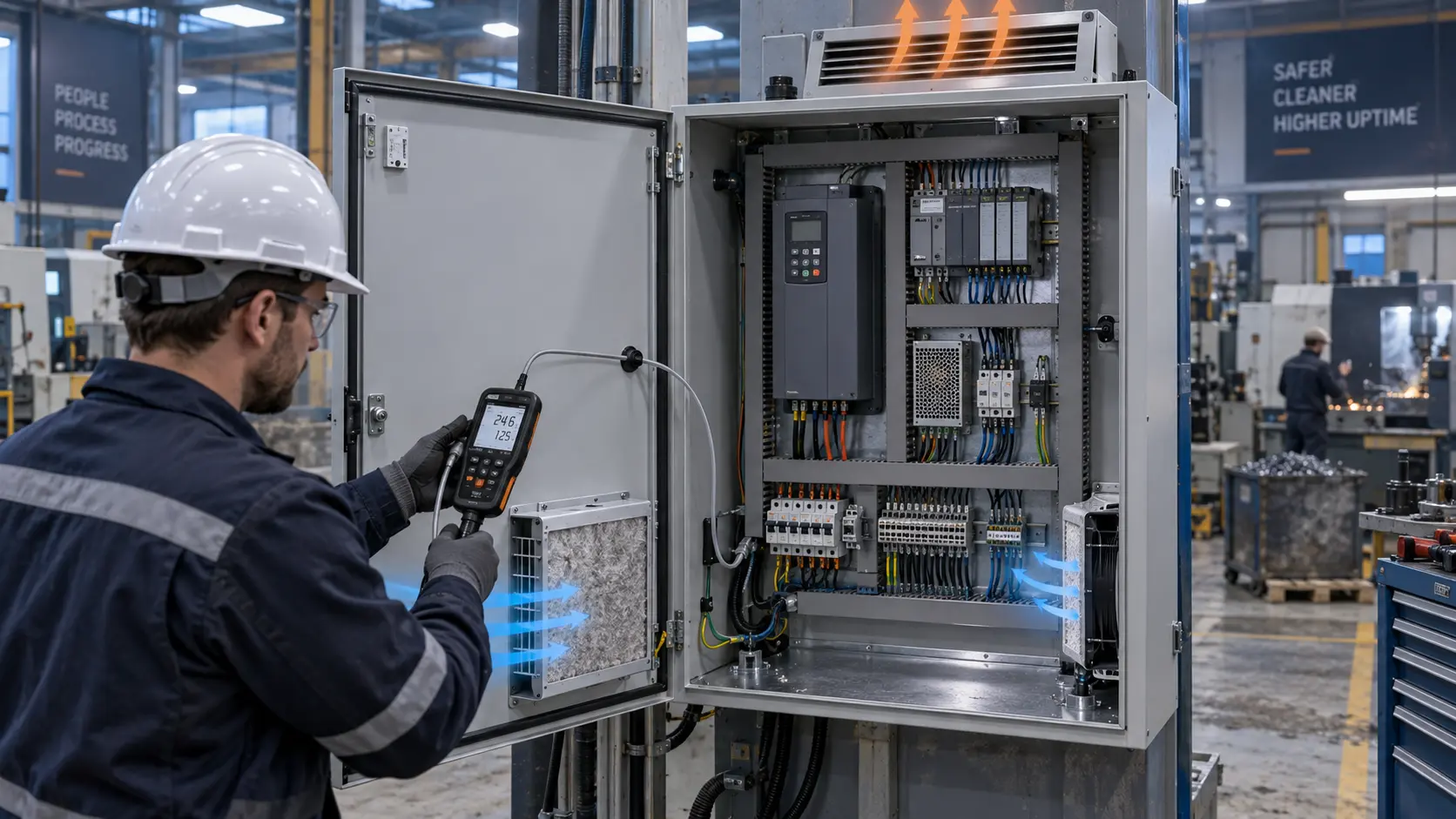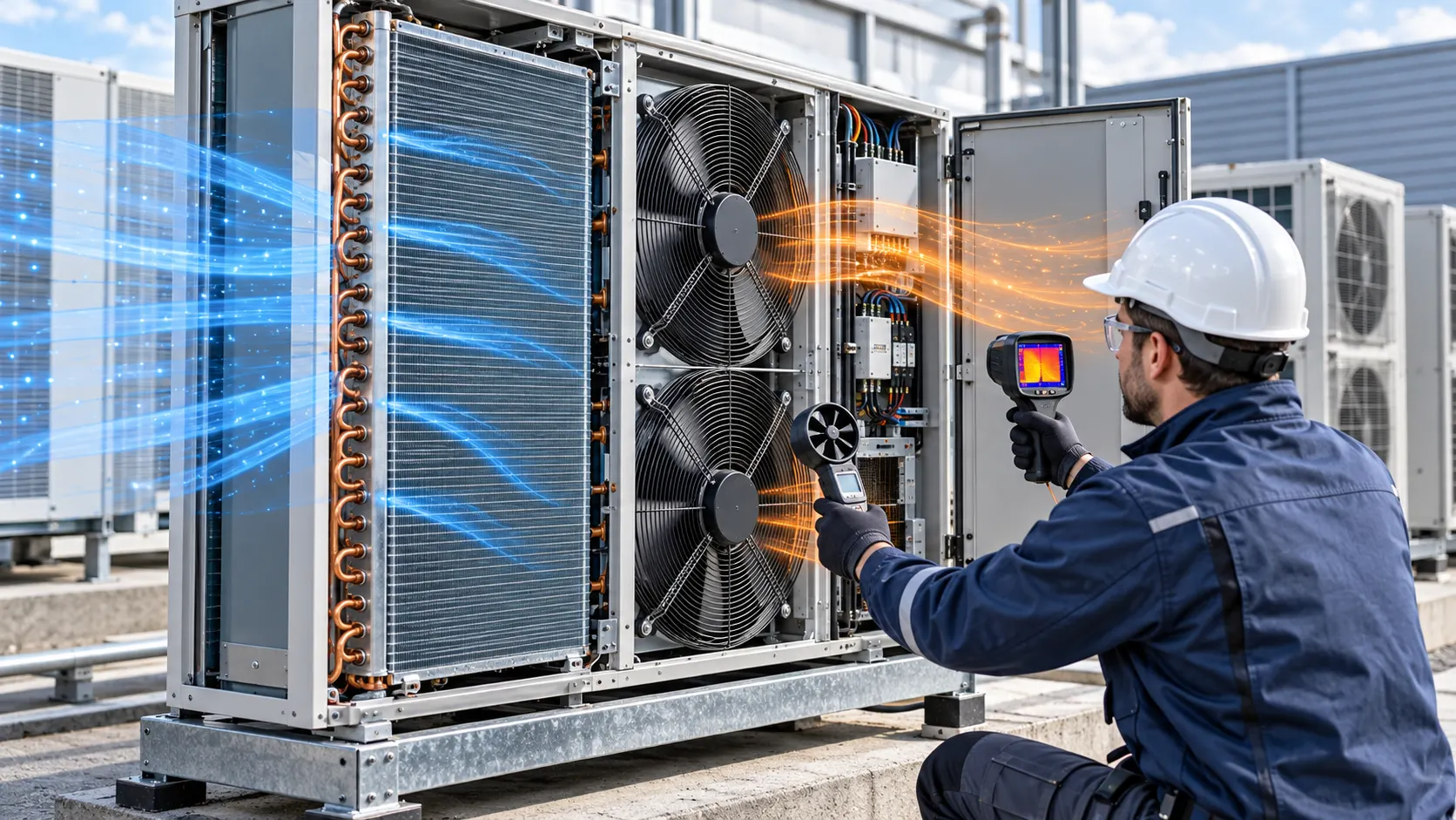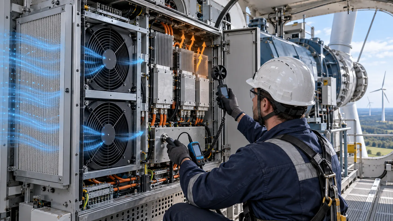
The Nacelle Problem: Converter Heat Meets Vibration and Weather
A wind-turbine converter cabinet has to reject heat while the nacelle vibrates, the filter loads and the outdoor environment changes. A fan replacement is therefore a thermal, mechanical and maintenance decision together.
This anonymised case pattern concerns a power-converter cabinet in a wind-turbine nacelle. The original cooling fans still ran, but the converter showed a rising heatsink temperature during sustained output, a vibration trend near one mounting panel and a fan fault after a long service interval. A clean workshop check did not reproduce the field condition because it had no loaded filter, nacelle vibration or cable movement.
The engineering team mapped the cabinet intake, filter, fan bank, heatsink, busbar area and exhaust. It also recorded nacelle orientation, service access, cable restraints, mounting stiffness and the environmental assumptions for temperature, humidity, salt and dust. The objective was not to claim a universal wind-turbine fan rating. It was to identify a fan-side operating point that could be sampled and validated in the real converter assembly.
This is an anonymised engineering method, not a turbine certification or a guaranteed production result. The turbine owner and converter maker remain responsible for the electrical, mechanical, safety, grid and environmental qualification of the complete system.
Why a Clean-Filter Test Hides the Field Duty
The fan sees the pressure of the filter, guard, heatsink and enclosure, while the turbine sees a changing environment over its service life.
A free-air fan value is measured with little or no system resistance. A converter cabinet adds filter media, intake mesh, fan guard, heat-sink fins, cable bundles, bends and exhaust openings. When dust or salt loads the filter, the system curve rises and the fan operating point moves to lower airflow. The motor can still report a normal speed while the converter receives less useful flow.
The review defined clean, service-limit and restriction states. Clean-filter data was kept for commissioning. The service-limit filter became the main release condition, and the restriction state checked alarm and derating response. Differential pressure was measured across the filter and across the complete fan assembly, with the instrument location and pressure definition recorded.
The team also distinguished positive and negative enclosure pressure. A negative cabinet can pull unfiltered air through cable entries and panel gaps. Positive pressure can increase leakage if the exhaust is too restrictive. Fan selection and sealing were therefore reviewed together rather than treating the filter as a separate procurement item.
The Engineering Hook: Average Airflow Does Not Protect Every Module
Power semiconductors, magnetics and control boards can have different thermal limits and different access to the cabinet air stream.
As an illustrative screening calculation, a converter cabinet rejecting 1,200 W with an allowed average air rise of 14 K would need Q = 1,200 / (1,200 x 14) = 0.0714 m3/s, or about 151 CFM. The 1,200 J/(m3 K) heat-capacity estimate is only a screening basis. The actual design still needs measured component losses, air density, local heatsink limits and the real pressure path.
The team mapped inlet temperature, heatsink-base temperature, board temperature and outlet temperature. A cabinet can show a reasonable average rise while a blocked channel leaves one IGBT, rectifier or capacitor bank hot. Airflow traverse, smoke or particle visualization and local temperature sensors were used together to find bypass and dead zones.
A provisional pressure example might be 80 Pa at the target flow with a clean filter and 125 Pa at the service limit. Those values illustrate the method only, not a MEGA Tech product specification. The release test must use the customer's measured filter, guard, heatsink and cabinet curves.
Sample Review: 120, 172 and 200 mm Candidate Families
The catalogue can narrow the sample plan, but the correct candidate is the one that meets installed airflow, vibration, control and environmental requirements.
For a compact control compartment or auxiliary electronics bay, a 120 x 120 x 38 mm DC axial family can be screened by voltage, thickness and required pressure. For a larger converter air path, 172 x 150 x 51 mm and 200 x 200 x 60 mm DC axial families are reasonable starting points. The larger frame may deliver more total air per fan, while the smaller high-pressure candidate may suit a more restrictive opening. Neither conclusion is valid without the measured system curve.
The project compared 12 V, 24 V and 48 V electrical options where the controller architecture allowed them. Voltage was not used as a proxy for performance. The sample review checked startup, connector, cable length, current protection, PWM, FG or RD feedback, minimum stable speed and behavior after a power interruption.
Use the 172 x 150 x 51 mm DC axial fan candidate, the 200 x 200 x 60 mm DC axial fan candidate and the fan selection tool as candidate starting points. Ask for a sample review against the real converter cabinet before freezing a replacement.
Vibration Review: Fan, Panel and Cable Restraint Form One System
A converter fan may pass a thermal test and still fail a nacelle review if its vibration reaches a panel, heatsink or cable route.
The team measured vibration at the fan frame, mounting panel and the closest sensitive component. It compared broadband acceleration and narrow-band peaks at the same fan speed, mounting torque and filter state. The purpose was to compare candidate samples under equal conditions, not to publish a universal vibration limit.
Mounting stiffness, gasket compression and cable restraint were tested together. A soft isolator can reduce transmitted vibration but may reduce the seal or allow the fan to move. A rigid bracket may preserve alignment while increasing panel transmission. A cable touching a cover or heatsink can create a field noise and wear problem that is incorrectly attributed to the motor.
The review also checked impeller clearance, guard contact, bearing behavior after thermal soak and the effect of nacelle orientation. A sample accepted on a horizontal bench is not automatically equivalent when the real equipment experiences tilt, vibration and repeated temperature cycles.
Control and Fault Feedback: PWM, FG/RD and Converter Protection
The fan interface must remain predictable while the converter changes output, the nacelle cools down and a fan or filter fault develops.
The controller was checked at startup, minimum command, nominal command, high-load command and brownout recovery. Voltage was measured at the fan connector during the converter's real switching and contactor sequence. Cable resistance, filters and protection devices can change the voltage seen by the motor even when the supply measurement looks correct.
FG and RD signals were verified at the receiving input. The record identified pulses per revolution, pull-up voltage, missing-pulse timeout, open-collector behavior and the response to a disconnected wire. A tachometer signal is not the same as an alarm output. The converter software must know whether a missing pulse means stopped fan, underspeed, wiring fault or a temporary startup state.
The converter maker defined derating, alarm and shutdown actions. MEGA Tech supplied fan-side samples and interface information. The fan supplier does not own the turbine's grid protection, emergency stop, fire strategy, power-stage safety or final fault logic.
Interactive: Watch Filter Loading and Converter Duty Move
The dynamic schematic shows why a nacelle fan review needs airflow, pressure, vibration and maintenance state in one test record.
The first panel shows a clean filter and a direct path across converter heatsinks. The second shows a loaded filter. The same fan command now meets a higher system resistance, so useful flow falls. The third panel shows the required response: compare clean and loaded points while also checking vibration and fan fault feedback.
The figure is qualitative, not CFD and not a product P-Q curve. The validation report should record fan voltage, current, command, feedback, airflow, pressure, temperature, filter state, vibration points, ambient, nacelle condition and instrument uncertainty. This makes the sample result traceable when a field unit later behaves differently.

Validation Sequence: Workshop, Nacelle and Service Condition
The replacement fan was not approved from a bench-only result. The sequence moved from controlled sample checks to the real converter assembly and service state.
Step one was documentation. The converter maker supplied the fan envelope, filter and frame, heatsink drawing, guard, cable route, mounting, vibration limit, noise target, voltage tolerance, control waveform, ambient range, altitude and service interval. The original fan's model and measured behavior were recorded for comparison.
Step two was an installed pressure-flow test. The team measured useful airflow at the critical heatsink path and pressure across the filter and assembly. It repeated the test at several commands and with the clean and service-limit filter. Air density and pressure definition were written beside the result.
Step three was thermal soak under representative converter output. Inlet, heatsink, board and exhaust temperatures were logged until repeatable. The test included the highest sustained power case and the lower-load case where the controller reduced fan speed. A short pass after startup was not accepted as a thermal result.
Step four was vibration and acoustic validation. The same fan command, mounting and filter state were used for original and candidate. The team checked panel resonance, cable contact, guard tone, rotational peaks and the response of sensitive components.
Step five was fault and maintenance response. The test covered fan stop, missing FG/RD, blocked intake, low voltage, restart and a filter service trigger. The turbine and converter owners retained responsibility for the complete protection strategy.
Validation Result: A Fan Replacement Basis With Maintenance Margin
The useful result was a traceable fan specification that connected the converter's thermal duty to the real nacelle environment.
The comparison sheet listed frame, depth, voltage, connector, control, feedback, mounting, airflow and pressure at the installed duty. It also listed current, sound spectrum, vibration, inlet and hotspot temperatures, filter differential pressure, ambient and converter output. A candidate passed only when the complete set met the owner's limits.
Catalogue values remained separate from project measurements. Model values were cited with their test condition. Screening calculations were labelled illustrative. Field or nacelle results included the actual equipment, load, temperature, filter, mounting and instruments. This separation prevents a plausible catalogue value from becoming an unqualified turbine claim.
Maintenance received a measurable basis. Filter pressure, useful airflow, fan current, feedback, noise and vibration could be trended together. A rising vibration level with normal FG could request service before a stopped-fan alarm. The exact thresholds belong to the converter maker and turbine owner.
How MEGA Tech Supports Wind-Converter Fan Customization
MEGA Tech develops and manufactures custom cooling fans, supporting fan selection, air-path review, sample validation and volume production around the customer's equipment.
We can review DC axial fans and compact blowers by installed airflow and pressure rather than frame size alone. The review can include filter and heatsink losses, shroud, seal and guard, flow direction, voltage tolerance, PWM, FG or RD feedback, connector, cable exit, vibration mounting, acoustic target and environmental assumptions. A candidate series then becomes a sample comparison plan for the converter cabinet.
Please provide the converter or cabinet sample, heat load by output mode, target airflow and static pressure at that airflow, ambient and altitude, voltage, quantity, control interface, connector, noise and vibration targets, filter condition, humidity or salt exposure, life assumption and service interval. For replacement work, send the current fan model, drawings, photos, controller waveform, measured temperatures, pressure and vibration data.
Our scope is the custom cooling fan, fan-side air-path review, sample validation and production support. The turbine and converter integrator retains responsibility for the generator, power electronics, grid interface, nacelle structure, fire protection, electrical safety, environmental qualification and final certification. We do not supply complete turbines, converter cabinets, filters as a certified environmental system or grid-control equipment.
Engineer FAQ
These answers help separate a wind-converter fan replacement from a complete turbine qualification.
Q: Can I select a replacement by matching fan size? A: No. Match installed airflow and pressure, voltage, control, feedback, vibration, noise, environment and filter condition.
Q: Does normal FG prove the converter is cooled? A: No. It proves a speed-related signal is present. It does not prove useful flow through the heatsink or a good filter seal.
Q: Should the fan be tested only in the workshop? A: No. Repeat the check in the converter assembly and include vibration, orientation, service condition and temperature soak.
Q: Does 48 V automatically improve reliability? A: No. Check the driver, voltage tolerance, startup, current protection, connector and fault input. Voltage is an architecture choice, not a performance guarantee.
Q: What should be trended in service? A: Trend fan feedback, current, filter pressure, useful airflow where practical, temperature and vibration. A stopped-fan alarm alone can miss gradual performance loss.
Q: Can MEGA Tech provide a sample recommendation? A: Yes. Send the fan size, voltage, quantity, airflow and pressure target, control, vibration, noise, environment, drawings and current measurements.
Questions for a Design Review
Use these questions before freezing a fan replacement for a wind-turbine converter cabinet.
What is the worst sustained converter output and the hottest component? What airflow is required at that component, and at what static pressure? What are the clean and service-limit filter losses? Does the test include the real guard, shroud, cable route, seal and nacelle orientation? Could salt, dust or condensation change the pressure path?
What vibration level is acceptable at the fan frame, panel and power module? Which tones are objectionable? What mounting torque, isolator and cable restraint are required? Does the candidate start and remain stable at minimum PWM duty and after brownout? What happens after fan stop, missing FG/RD, blocked filter or loss of control?
Before asking for a sample, send the current fan model, converter drawings or physical sample, filter and heatsink data, target airflow and static pressure, fan size, voltage, quantity, control interface, connector, ambient, altitude, vibration, noise, humidity, salt, life assumption and measured thermal data. Use the MEGA Tech products catalogue, the fan selection tool and WhatsApp engineering contact. Request the P-Q curve or a custom specification at inquiry@cnmegatech.com.