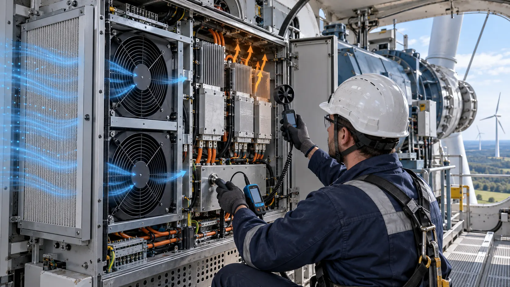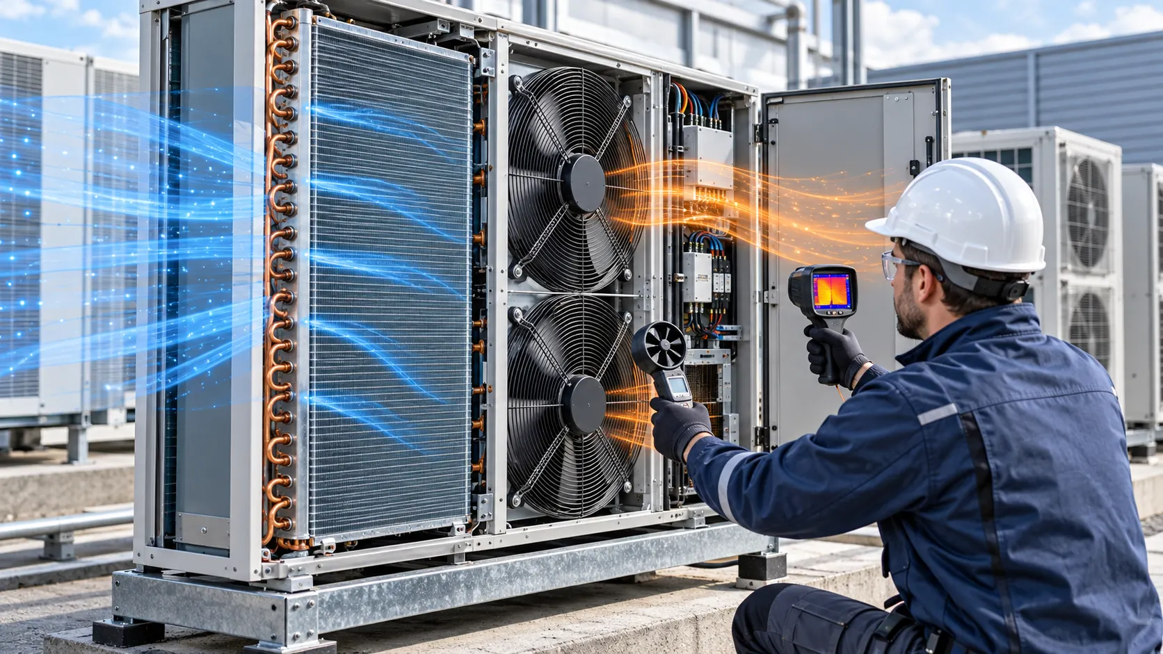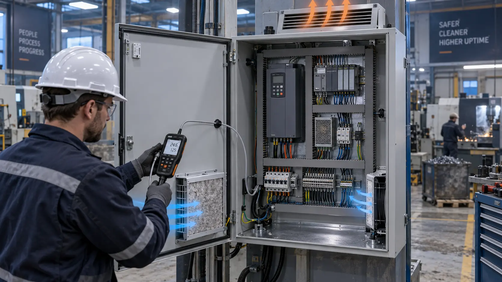
The Control Cabinet Needed More Than a Same-Size Replacement
An anonymised automation integrator needed to replace a cabinet fan while moving from a field-proven design toward a stable production supply.
The existing control cabinet fan had become difficult to source for a new machine platform. The replacement candidate matched the opening and nominal voltage, so it looked like a simple purchasing substitution. The first installed test showed why that assumption was unsafe: after the filter, louver, cable duct and drive heatsink were installed, the useful airflow at the limiting component was lower than the free-air catalogue number suggested.
The project was not only a fan-selection exercise. It had three linked goals: keep the cabinet thermal margin, preserve the electrical and mechanical interface, and create a repeatable path from one engineering sample to pilot builds and then volume production. The team needed evidence that an operator could install the fan consistently and that a later supplier lot would still be judged against the same operating point.
Customer identity and released acceptance values remain confidential. This is an anonymised engineering case pattern, not a universal replacement guarantee. The method is useful when a VFD, UPS, servo drive, PLC or industrial power cabinet needs a custom or alternative cooling fan.
Define the Cabinet Heat Load and Allowable Temperature Rise
The fan should be selected from the cabinet duty, not from the old fan label alone.
The integrator listed the losses from the drive, power supply, braking circuit, UPS electronics and control hardware. It separated continuous operation from short high-load cycles and recorded the intended ambient range. A cabinet may be acceptable at a comfortable workshop temperature and lose margin on a warm production floor, inside a machine bay or with nearby heat recirculating at the inlet.
The thermal review also identified the actual decision points. A single air-outlet temperature can hide a hot drive terminal, DC-link area or power module. Sensors were placed at the fan inlet, the limiting component air inlet, the component surface and the cabinet outlet. The record stated which point controlled the acceptance decision and under which equipment state.
These inputs did not need to be perfect before the first sample. They did need to be visible as assumptions. Heat load, inlet temperature, allowable rise, airflow target and static-pressure target were updated as the cabinet became more representative.
The integrator also separated heat that stayed inside the cabinet from heat that entered from the machine or room. A drive cabinet beside a hot process can have a different inlet basis from the same cabinet on a clean test bench. The release record therefore stated whether the result represented free surrounding air, a machine compartment or a measured recirculation condition.
| Input | Why it matters | Evidence to retain |
|---|---|---|
| Cabinet heat load | Sets the required cooling duty | Loss list by equipment state |
| Ambient and inlet | Sets available thermal margin | Sensor position and temperature basis |
| Filter and louver | Creates system resistance | Pressure-drop data or measured points |
| Fan interface | Controls speed and fault behavior | Voltage, PWM, FG/RD and connector record |
| Service condition | Changes airflow over time | Filter limit and maintenance assumption |
Measure the Installed Pressure Path
The replacement must deliver useful airflow through the cabinet resistance, not only in open air.
The team mapped the complete route from inlet grille to filter, fan, heatsink, cable path and exhaust louver. It checked whether the fan was pushing or pulling through the filter and whether the cabinet used positive or negative pressure. Door seams, cable entries and service covers were included because bypass air can make the fan look healthy while the power device receives too little flow.
Pressure and airflow measurement points were chosen before the comparison. The record distinguished pressure across the fan from pressure across the filter or the whole cabinet path. It also stated the reference condition for airflow, the equipment load and the filter state. Without those boundaries, two apparently different results may simply be measurements at different locations.
A compact axial fan may suit a short direct path; a centrifugal blower may be worth reviewing when the path turns or becomes restrictive. The choice remained conditional on envelope, voltage, current, control, noise, mounting and the measured operating point. Same outline dimensions were treated as a packaging constraint, not proof of equivalence.
The pressure boundary was kept consistent during each comparison. Pressure across a filter is not the same as pressure across the fan, and a cabinet outlet reading does not by itself show what reaches the heatsink. The team recorded tap locations and filter condition beside each result so that engineering, purchasing and service teams did not compare different boundaries under the same word ‘pressure’.
Sample One: Prove the Replacement in the Real Cabinet
The first sample was used to expose the real constraint before the production specification was frozen.
The customer supplied the existing fan, cut-out, mounting drawing, connector, wire length, supply tolerance, filter area, louver and available depth. The sample review compared the original and candidate with the same equipment load and air-path parts. Voltage was measured at the fan connector rather than assumed from the power-supply setting.
The test logged fan current, command, actual RPM or FG/RD feedback, inlet temperature, component temperature, pressure and airflow. If the fan reached its expected speed but the hotspot remained high, the next question was bypass, heat-sink contact or insufficient pressure. If the fan did not start reliably, the team checked voltage drop, controller timing and the low-speed operating region before simply requesting a larger fan.
This sample was not a production promise. It was a controlled experiment. Every proposed change had a reason and a measurement that could show whether the change helped. That kept a purchasing substitution from hiding an air-path or assembly problem.
The first sample review also checked whether the cabinet could be assembled without disturbing the fan. A replacement that needs a cable to cross the inlet, a guard to be removed or a gasket to be compressed differently may be acceptable on a workbench but not on a production line. Mechanical access, service clearance and the order of assembly were recorded with the thermal result.

Sample Two: Tune Control, Noise and Vibration
The best command is the one that maintains useful cooling without creating a new electrical or acoustic limit.
The controller was checked across the intended supply tolerance and speed range. PWM percentage was not treated as a universal RPM value. The low-speed region was reviewed for startup and stable operation; the high-speed region was reviewed for current, noise, vibration and actual thermal benefit. FG or RD feedback was compared with pressure and temperature because a valid pulse signal alone does not prove useful airflow.
The mounting review checked fastener preload, frame distortion, elastomer support, guard clearance, connector latch and cable exit. A cable that bridges an isolated mount can create a force path. A panel or louver can amplify a tone. A small gap can create a bypass. These details belonged in the sample record before the pilot build, not in a troubleshooting note after production.
The finished-cabinet acoustic position was used where possible. The operating state, microphone position, panels and filter condition were retained with the result. A lower free-air noise value was not accepted if it came from lower installed airflow.
The fault check was kept separate from the thermal check. A stopped fan, missing FG/RD signal, loose connector and blocked filter can produce different machine actions. The cabinet controller or machine builder defined the response, while the fan sample supplied evidence about speed, current and feedback behavior. This separation prevented a fan-side signal from being mistaken for complete machine safety logic.
| Check | Failure if missed | Pilot evidence |
|---|---|---|
| Connector voltage | Startup or feedback becomes intermittent | Voltage at pins and contact inspection |
| PWM and actual RPM | Command does not represent installed cooling | Command, speed and airflow trace |
| Mount and harness | Vibration or bypass changes after assembly | Clearance, retention and installed inspection |
| Noise position | A thermal fix creates a field complaint | Defined position and operating state |
| Fault response | Alarm has no clear machine action | Controller decision and recovery record |
Build the Pilot Around Repeatable Assembly
Pilot production changes the question from ‘does this sample work?’ to ‘does the same result survive the next build?’
The pilot used the intended fasteners, connector, harness route, grille, gasket, cover and service sequence. The work instruction stated fan orientation and airflow direction. It also identified which details could change the inlet or outlet clearance. If a cable could be installed in two positions, the route and retention method became part of the controlled assembly rather than an informal operator preference.
The inspection plan focused on details that could move the operating point: connector seating, frame clearance, fastener condition, filter position, gasket compression, louver blockage and cable retention. Thermal and airflow checks were repeated on representative builds. This separated fan-design variation from assembly variation and gave the integrator a practical escalation path.
The objective was not an unnecessarily heavy inspection process. It was to identify the small number of details that mattered, assign an owner and keep them visible in the pilot record.
Where practical, the team used a simple first-article checklist and a short repeatability check rather than relying on an operator's memory. The checklist did not replace the thermal validation; it protected the conditions under which the thermal validation had been obtained. That made it easier to investigate a later temperature increase without immediately blaming the fan supplier.
Set the Filter Service Limit and Change Triggers
A production fan specification should explain what happens as the cabinet ages and what changes require another sample.
The filter review used differential pressure, delivered airflow and component temperature rather than a calendar interval alone. A clean-filter result could not represent the end-of-service condition. The maintenance trigger was tied to the cabinet's actual duty and the thermal margin remaining at the limiting component.
The team also listed change triggers: a new filter area, louver, heatsink, cover, controller schedule, connector, cable route, mounting bracket, ambient range or service orientation. A different supplier lot could require confirmation if the motor, control interface or operating point changed. This made later procurement discussions more precise.
The result was a controlled release boundary. It said which fan configuration, air path, filter state, equipment load and assembly condition were represented. It also said which future changes would reopen the review rather than being silently treated as equivalent.
This change list was useful beyond the first machine. If a future cabinet used a larger filter, a different louver or a revised drive, the team could see which evidence remained reusable and which part of the fan-side review needed repeating. A documented boundary is faster than rediscovering the same failure through a field complaint.
Move From Pilot Evidence to a Volume Specification
The handoff to production works when engineering, purchasing and assembly can all identify the same approved configuration.
The release file captured the fan envelope, voltage tolerance, current, airflow and static pressure at the installed point, control interface, connector, cable exit, mounting, noise target, temperature and environment. It included the measured sensor positions, filter state, load state and test assembly condition. The P-Q curve was kept with the mechanical drawing and wiring information rather than separated into an untraceable email.
Purchasing received the approved configuration and the substitution boundary. Assembly received orientation, connector, cable and inspection instructions. Service received the filter trigger and replacement constraints. Engineering retained the conditions under which a new sample was required. This reduced the risk that a later order would match only the external frame while changing the useful operating point.
For a small manufacturer, this handoff is also a communication tool. It helps the fan supplier understand whether the next request is a repeat order, a voltage variant, a connector change or a new operating point.
It also gave procurement a safer language for alternatives. ‘Same size’ described the mechanical envelope only. The approved configuration included the operating point, electrical interface, control response, mounting, environment and service assumptions. If any of those changed, the request was routed back to engineering for a sample decision instead of being treated as an automatic substitution. That simple rule protected both the pilot schedule and the final customer machine.
How MEGA Tech Supports Custom Industrial Cabinet Fans
MEGA Tech helps automation teams move from a cabinet problem to a sample that can be measured in the real enclosure.
MEGA Tech develops and manufactures custom cooling fans, from fan selection and air-path review through sample validation and volume production. We can review DC axial fan and centrifugal blower options against the installed airflow and static-pressure requirement, with attention to voltage, control, connector, mounting, noise and environmental conditions.
For a first review, send cabinet heat load, allowable temperature rise, ambient range, filter and grille pressure drop, fan envelope, voltage tolerance, control interface, noise target, mounting direction, service interval and quantity. If the data is incomplete, send the existing fan part number, cabinet photos and any measured pressure or temperature points. A sample can then be assessed against the customer's real assembly.
MEGA Tech is the custom cooling-fan manufacturer. Complete cabinets, coils, liquid loops, controllers, machine safety, EMC, heat-sink design and system qualification remain with the cabinet builder and system integrators. Start with the fan selection tool, review the DC axial fan range, or request a sample on WhatsApp.
Engineer FAQ
These questions usually decide whether a control-cabinet replacement fan is ready for a production BOM.
Q: Can I replace a fan because the frame and voltage match? A: Not by those two values alone. Confirm installed airflow, static pressure, current, control, mounting, environment and service condition.
Q: Does normal RPM prove the cabinet is cooled? A: No. Filter loading, bypass leakage and poor distribution can reduce useful flow while RPM remains normal.
Q: Should the fan run at full speed all the time? A: Not automatically. Compare thermal margin, noise, current, pressure and control stability across the required duty states.
Q: What should I send for a brand-alternative review? A: Send the current fan, size, voltage, P-Q data if available, control signals, heat load, filter, pressure path, ambient, noise target and quantity.
Q: Can MEGA Tech provide a custom sample? A: Yes. We review the operating point, define the fan-side requirements and validate the sample on the customer's assembly before production release.
Questions for an Industrial Cabinet Fan Design Review
Use this checklist with thermal, mechanical, electrical, controls, manufacturing, service and procurement teams.
- Which equipment state defines the limiting cabinet heat load?
- What airflow and static pressure are required after the filter, louver, heatsink and outlet are installed?
- Where are fan inlet, component and outlet temperatures measured?
- What voltage tolerance and harness drop exist at startup and steady operation?
- What PWM, FG/RD or alarm behavior defines a valid fan state?
- Can the grille, filter, cable, gasket or cover create restriction, bypass or recirculation?
- Which connector, mounting and cable-route details must be repeated in every pilot build?
- What pressure or temperature condition defines the filter service trigger?
- Which change triggers a new sample: fan, filter, louver, heatsink, cover, controller or mount?
- What exact information should accompany a sample request: size, voltage, airflow, pressure, quantity and environment?