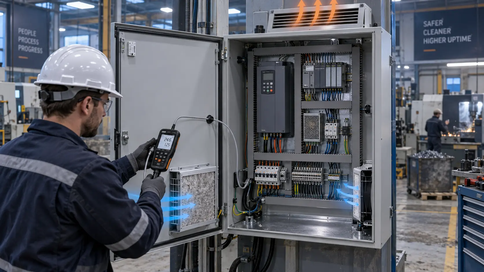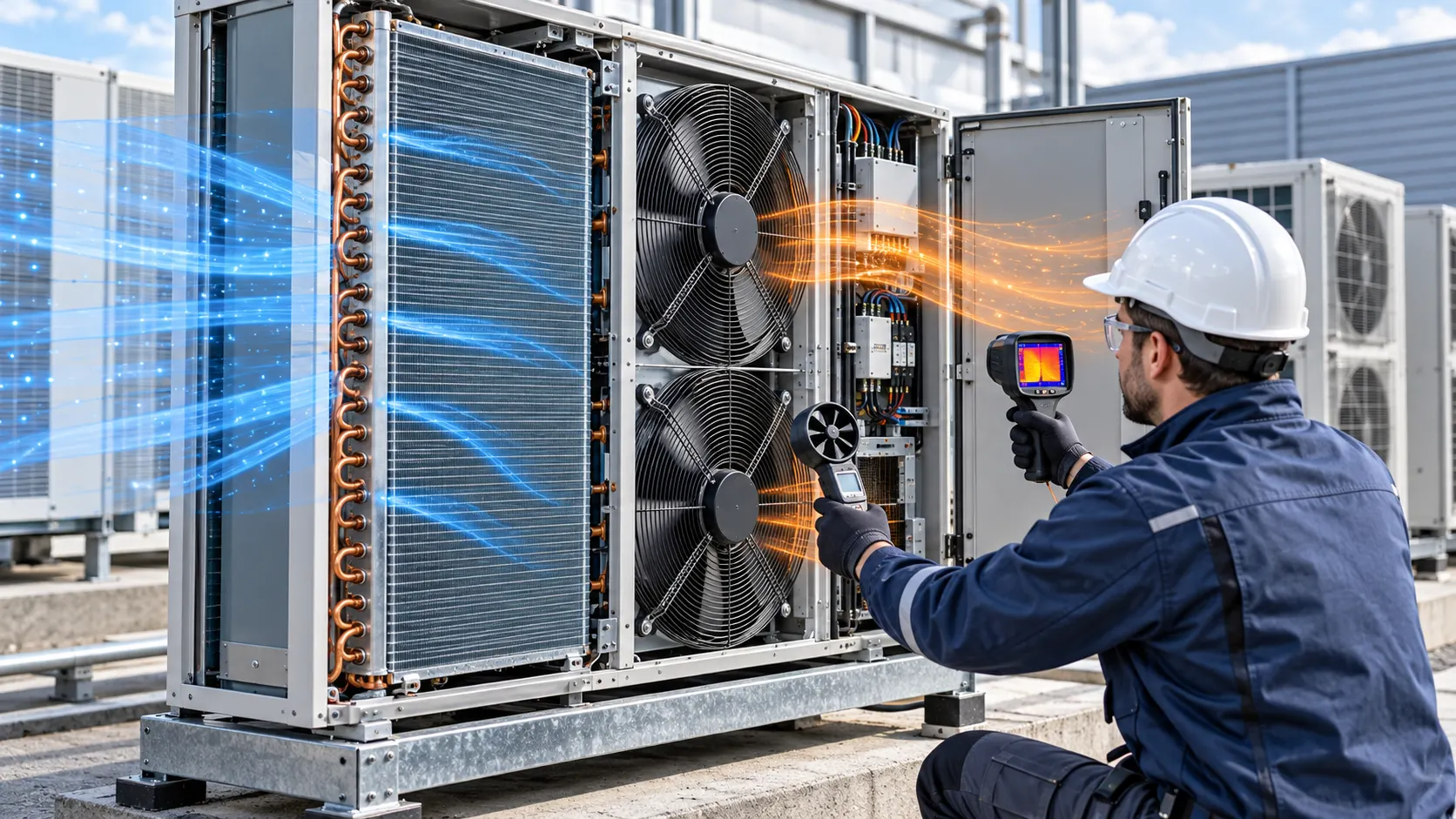
The Outdoor-Unit Problem: Refrigerant Duty Depends on Air-Side Reality
A heat pump or HVACR outdoor unit can have the right coil and compressor yet lose capacity, efficiency or acoustic margin when its condenser fan does not hold the installed air-side duty.
This anonymised case pattern concerns a replacement fan review for an outdoor condenser unit. The original fan matched the opening, but the system showed a high-head-pressure alarm during hot afternoons and a tonal noise complaint during night operation. The coil was clean in the first inspection. The more useful diagnosis was that the fan, guard, coil, discharge hood and nearby wall formed a system whose resistance changed with operating condition.
The team mapped air entering the coil, crossing the fins, leaving the fan guard and returning from nearby surfaces. It recorded outdoor temperature, refrigerant-side operating state, fan voltage, current, speed, pressure where practical, coil temperature and sound at the agreed measurement location. The purpose was not to select a fan from a free-air number, but to establish the air-side duty that supported the refrigeration requirement.
This is an engineering case pattern, not a universal HVACR performance claim. The final fan and control must be approved by the equipment maker against its refrigerant circuit, coil, defrost sequence, safety controls, weather exposure and acoustic limits.
Why Free-Air Airflow Does Not Predict Condenser Performance
The condenser sees pressure from fins, guards, grilles, discharge geometry and recirculation. The fan's free-air rating does not include those losses.
A fan curve describes how airflow falls as static pressure rises. A condenser coil adds a pressure drop that depends on face velocity, fin condition and air density. A guard, inlet grille or discharge hood adds more. A wall, parapet or adjacent unit can return hot discharge air to the intake, effectively increasing the thermal duty without changing the fan's command.
The review defined clean-coil, service-condition and restricted-path states. Clean-coil data was useful for commissioning. Service condition included the agreed fin contamination and guard state. A restriction check represented a maintenance or fault boundary, not a normal operating point. The fan candidate was judged at the pressure and flow required in the service state, not at the largest number in a catalogue summary.
Air density also changes with outdoor temperature and altitude. A volumetric flow reading at one condition cannot be copied into another condition without recording density and measurement basis. The report therefore kept measured airflow, fan pressure, refrigerant state and ambient condition in the same row so that the thermal result could be reproduced.
The Engineering Hook: High Ambient Changes Both Heat Load and Fan Margin
On a hot day, the outdoor unit has less thermal margin while the air path and fan may deliver less useful mass flow.
As an illustrative screening example, if a condenser must reject 6 kW of heat and the air-side design allows a 10 K average air rise, a rough volumetric screen using 1,200 J/(m3 K) gives Q = 6,000 / (1,200 x 10) = 0.50 m3/s, or about 1,060 CFM. This is not a condenser selection or product specification. The actual refrigerant circuit, coil conductance, face area, air density and allowable condensing temperature control the release result.
The team used the screening calculation only to catch an obviously undersized airflow path. It then measured coil inlet and outlet temperature, refrigerant pressures, compressor condition and fan operating point. A higher fan flow is not automatically better if it increases noise, bypasses the coil, overcools during defrost or drives the system outside its control envelope.
The high-ambient test was repeated after the unit had reached thermal steady state. A short test after startup can make the coil look healthy while the enclosure, compressor compartment and surrounding air have not yet reached their worst condition. The acceptance record stated outdoor temperature, solar exposure, wind, unit spacing, fan command and refrigeration mode.
Sample Review: Large DC Axial Candidates for a Ducted Coil Path
Large axial fan candidates can be screened by envelope and pressure, but an outdoor HVACR release also needs weather, motor control, noise and coil validation.
For a compact or modular coil path, the 120 x 120 x 38 mm family may be a control or electronics-compartment candidate rather than the main condenser fan. Its use depends on the actual airflow division and must not be confused with the airflow needed through a large outdoor coil.
For larger air paths, the 172 x 150 x 51 mm and 200 x 200 x 60 mm DC axial families are logical catalogue starting points for a custom sample review. The 172 mm candidate fits a more compact high-pressure path; the 200 mm candidate can be considered where the cabinet and coil allow a larger opening. The correct choice is the one that meets the installed coil pressure, air volume, noise, control and environmental requirements.
Review the 172 x 150 x 51 mm DC axial fan candidate, the 200 x 200 x 60 mm DC axial fan candidate and the fan selection tool. These are candidate product records for sample evaluation. They do not prove condenser capacity, weather resistance, refrigerant performance or system efficiency without installed testing.
Coil, Guard and Discharge Geometry: The Fan Does Not Work Alone
The outdoor-unit assembly determines whether the fan's pressure becomes useful flow through the coil or is lost in bypass and recirculation.
The review checked the distance between fan and coil, fan guard open area, shroud overlap, coil edge clearance and discharge hood. A small gap around a shroud can let air take an easier route around the coil. A guard with a large wire obstruction can add noise and pressure loss. A discharge opening aimed at a wall can return warm air to the intake even when the fan produces its expected flow.
The team temporarily sealed suspected bypass paths and repeated the thermal test. The change in coil face velocity was compared with the change in refrigerant pressure and compressor input. This did not create a permanent product solution by itself; it identified whether the next design action belonged to the fan, shroud, guard, coil layout or site clearance.
The outdoor enclosure also needs service access. A larger fan may reduce speed and tonal noise, but it can be a poor replacement if the guard, motor, cable route and coil service panel cannot be maintained. A sample must be checked in the complete mechanical envelope, not on a bare bench.
Noise Review: Night Operation Is an Installed-System Problem
Outdoor fan noise is shaped by blade-pass tones, guard interaction, panel resonance, speed transitions and reflections from nearby buildings.
The project measured sound at the property or operator boundary defined by the equipment owner, as well as close to the unit for diagnosis. The report separated broadband sound from tonal peaks. A lower overall dBA value can still leave a prominent tone that neighbors notice. The fan was therefore compared at the same condenser duty and airflow, not merely at the same PWM command.
Speed control was checked for abrupt steps, hunting and resonance. A smooth ramp can reduce audible changes during load transitions. Night operation may use a lower fan command, but only if the refrigerant head-pressure and coil temperature remain within the equipment maker's limits. Quiet operation is not a license to reduce airflow below the required thermal duty.
Guard, grille and shroud geometry were inspected when a tone changed after installation. The source can be an interaction between blades and a nearby wire, a narrow opening or a panel mode. The replacement plan included mounting stiffness, isolator condition, cable restraint and fastener torque alongside the fan electrical data.
Control and Fault Feedback: PWM, FG/RD and Defrost Transients
The condenser fan must behave correctly during startup, speed control, defrost, low ambient protection and fault recovery.
The controller was checked for voltage tolerance, startup current, minimum stable speed, PWM frequency and duty range. The actual voltage at the motor connector was measured during compressor startup and fan acceleration. A long cable, contactor, protection device or filter can create a transient that is invisible at the supply terminals.
FG or RD feedback was verified at the control board. The test identified pulses per revolution, pull-up voltage, missing-pulse timeout and the behavior after a loose connector. The system owner defined what should happen after a fan fault: alarm, capacity reduction, controlled shutdown or service request. A fan supplier cannot choose the complete refrigeration safety response.
Defrost and low-ambient modes were treated as separate states. Fan direction, speed and timing can change during defrost, and a replacement must not be assumed compatible because it runs correctly in cooling mode. The sample plan recorded every command state used by the outdoor unit and checked restart after a power interruption.
Interactive: Watch the Coil Duty and Recirculation Move
The dynamic schematic shows why a condenser fan review needs airflow, pressure and surrounding installation checks together.
The first panel shows air crossing the coil with a clean pressure path. The second shows a restricted or recirculating installation. The fan can still spin and the control can still report its command, while the coil sees less useful mass flow and warmer entering air. The third panel turns that observation into a test: compare nominal and high-ambient operating points with the actual coil, guard, hood and site clearances.
The figure is qualitative and does not replace a fan P-Q curve or a refrigeration test. Record the fan voltage, current, speed, pressure, airflow, coil temperatures, refrigerant pressures, outdoor temperature, wind and sound level. Repeat the measurement after service condition or a defined fin restriction so that the result remains useful over the equipment life.

Validation Sequence: Clean Coil, Hot Ambient and Service State
The replacement fan was evaluated through the conditions that matter to an outdoor unit, not only the easiest laboratory state.
Step one was mechanical and environmental fit. The developer supplied coil drawing, fan envelope, guard, shroud, grille, cable route, enclosure, drain and service access. The review checked mounting, rotating clearance, seal, weather exposure assumption and the possibility of recirculation from neighboring equipment or a wall.
Step two was a clean-coil baseline. The team recorded refrigerant operating state, compressor input, coil inlet and outlet temperatures, fan voltage and current, fan command, airflow and sound. This made it possible to see whether a candidate changed the air-side behavior before a high-ambient test.
Step three was high ambient. The unit ran at the specified load until the refrigerant and coil reached a repeatable state. The test captured head pressure, discharge temperature, compressor protection status, coil temperature, fan operating point and sound. Any screening number was labelled illustrative; the actual thermal result came from the equipment test.
Step four was service condition and fault response. The test covered fin contamination or the agreed pressure increase, blocked airflow warning, fan stop, missing FG/RD, low voltage, restart and a change from day to night command. The equipment maker owned the protection and alarm logic; the fan sample supplied evidence for the fan-side behavior.
Validation Result: A Replacement Basis That Protects Capacity and Noise
The useful result was a traceable fan specification that connected the refrigeration duty to the real outdoor air path.
The comparison record listed the original fan and candidates by size, depth, voltage, control, feedback, connector, guard and mounting. It also listed airflow and pressure at the installed coil path, current, sound spectrum, coil temperatures, refrigerant operating state, outdoor temperature and service condition. The candidate was not accepted because it had the largest free-air value; it was accepted only if the complete unit passed its thermal, acoustic and control requirements.
The project kept fan data and system data separate. Catalogue values were tied to model and test condition. Condenser capacity and efficiency were tied to the specific coil, compressor, refrigerant circuit, ambient and control state. This prevents a fan supplier's catalogue value from being turned into an unqualified HVACR capacity claim.
Maintenance also received a measurable basis. Coil cleaning, differential pressure, fan current, feedback, noise and head-pressure trend could be combined into a service trigger. The owner could distinguish a dirty coil, a failing fan, a blocked guard and a recirculation problem instead of increasing speed blindly.
How MEGA Tech Supports HVACR Fan Customization
MEGA Tech develops and manufactures custom cooling fans, supporting fan selection, air-path review, sample validation and volume production around the customer's equipment.
We can review large DC axial fan candidates and compact fan assemblies by installed airflow and pressure, not by outline dimensions alone. The review can include coil and guard pressure drop, shroud, discharge geometry, recirculation, voltage tolerance, PWM, FG or RD feedback, connector, cable exit, mounting, vibration, acoustic target and environmental assumptions. The output is a sample comparison plan for the customer's outdoor unit.
Please provide the coil drawing, fan and guard dimensions, required airflow and static pressure at that airflow, refrigerant operating states, ambient range, altitude, wind and spacing assumptions, voltage, quantity, control interface, connector, noise target, service condition and life assumption. For replacement work, send the original fan model, operating waveform, measured head pressure, coil temperatures, sound data and photographs of the installation.
Our scope is the custom cooling fan, fan-side air-path review, sample validation and production support. The HVACR equipment maker or system integrator retains responsibility for the refrigerant circuit, coil, compressor, defrost, pressure protection, weather enclosure, electrical safety, building installation and final certification. We do not supply complete heat pumps, condensers, coils or refrigeration systems.
Engineer FAQ
These answers help separate a condenser fan replacement problem from a complete HVACR system design problem.
Q: Can I choose a condenser replacement by matching fan diameter? A: No. Check installed airflow and pressure, coil face velocity, voltage, control, feedback, noise, weather and the complete discharge path.
Q: Does higher airflow always improve condenser performance? A: No. It can increase noise, bypass the coil, change control behavior or create recirculation. The refrigeration test decides the acceptable point.
Q: Should high ambient be tested only at maximum fan speed? A: No. Test the actual control sequence, including ramp, minimum speed, high-speed protection and restart.
Q: Is a clean coil enough for release? A: No. Include the agreed service condition and a fault or restriction response. Clean-coil data is a baseline, not the whole life cycle.
Q: What should be measured for a sample? A: Measure airflow, pressure, voltage, current, speed, PWM, FG/RD, coil temperatures, refrigerant pressures, ambient, sound and service state.
Q: Can MEGA Tech recommend a sample? A: Yes. Send the coil and fan drawings, airflow and pressure target, voltage, quantity, control, noise, environment and current measurements.
Questions for a Design Review
Use these questions before freezing a heat-pump or HVACR outdoor-unit fan replacement.
What air-side airflow is required through the coil at the worst ambient and refrigerant duty? What is the coil, guard, grille and discharge pressure drop at that airflow? Could a wall, parapet, adjacent unit or hood return warm air to the intake? Is the measured fan point based on the real shroud and guard, or a bare fan bench?
Which fan voltage, PWM, FG or RD interface does the controller support? What happens during compressor startup, defrost, low-ambient protection, power loss and a missing feedback signal? What noise limit applies at the property or operator boundary, and are tonal peaks measured separately from broadband dBA?
For a sample review, send the current fan model, coil and enclosure drawings, fan size, target airflow and static pressure, voltage, quantity, control interface, connector, ambient and altitude, spacing, noise target, service state and measured refrigerant or thermal data. Use the MEGA Tech products catalogue, the fan selection tool and WhatsApp engineering contact. Request the P-Q curve or a custom specification at inquiry@cnmegatech.com.