Fan noise is a clinical problem, not a comfort issue
In medical environments, fan noise is part of the clinical picture — and sometimes part of the procurement decision.
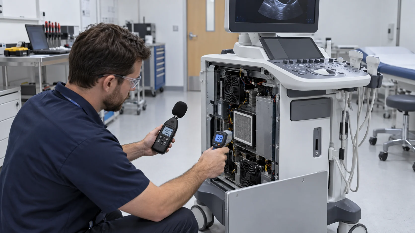
Picture an ultrasound cart wheeled into a neonatal ward at 3 a.m. The image on the screen is perfect. The fan inside the cart is not — a thin, reedy whine, just loud enough to turn heads in a room where every decibel feels clinical, where a nurse is trying to keep a premature infant asleep. Nobody specified that whine. Nobody tested for it. It simply showed up at system integration, six weeks before a regulatory submission, when changing anything costs ten times what it would have cost at the concept stage.
Or picture a home ventilator on a nightstand: the patient finally asleep, the partner awake, listening to a small blower hunt up and down all night — ramping, overshooting, settling, ramping again — because the speed-control loop was tuned for a server room, not a bedroom.
Yet most fan datasheets are still written for servers and telecom racks: free-air CFM, a single dBA number, an L10 life figure quoted at 40 degrees in clean air. Bridging the gap between that datasheet and a device that sits next to a patient is the thermal engineer's real job, and it is mostly a job of asking questions the datasheet never answers.
This article is a field guide for that job: what IEC 60601-1 actually asks of you, where medical fan projects usually fail, five selection checkpoints that matter specifically for medical devices, and a sample-validation checklist that catches the problems datasheets never show.
Why medical thermal design faces three pressures at once
Acoustic limits, rising thermal loads, and unforgiving reliability targets — all tightening at the same time.
First, acoustic limits — and psychoacoustics. Equipment that operates near patients faces noise expectations far stricter than industrial gear. But the raw decibel number is only half the story. Human hearing is ruthless about pure tones: in a quiet ward at night, a blade-pass whine sitting clearly above the broadband floor will dominate perception even when the A-weighted total looks respectable on paper. A fan that passes at 35 dBA in the datasheet can still fail the moment a clinician hears it in the real room.
Second, thermal loads keep climbing. Imaging electronics, analyzer optics, and high-density power stages keep getting hotter while enclosures shrink for bedside, portable, and point-of-care use. The fan is asked to move more air through tighter, more convoluted air paths — behind grilles, through filters, around densely packed boards, past heatsinks with millimeter clearances. Higher impedance pushes the operating point toward higher speeds and higher static pressure, and both fight the first pressure directly.
Third, reliability targets are unforgiving. Continuous, round-the-clock operation is the normal case, with an expectation of years of service and zero unscheduled downtime. Nobody wants to issue a field correction because a commodity fan wore out inside a high-value instrument, and nobody wants to explain to a regulator why the cooling subsystem's life analysis was a catalogue number copied into a spreadsheet. Bearing life, start-stop endurance, and behavior at elevated internal temperatures have to be designed in from the start.
What IEC 60601-1 actually governs
The standard addresses the complete medical electrical equipment — never the fan by itself.
The single most useful clarification in this whole topic: IEC 60601-1 is a system-level safety standard for medical electrical equipment. It does not certify fans. Any supplier offering an IEC 60601-1 certified fan is either confused or hoping that you are. For background on the standard family, see the IEC 60601 overview and the FDA medical device pages.
What the standard does do is set requirements that trickle down into every component decision, and the fan sits at the intersection of several of them. Leakage current and insulation: patient-connected or patient-adjacent equipment lives under strict leakage limits, and the insulation scheme — creepage distances, clearances, grounding continuity — covers everything inside the enclosure, including the fan motor, its lead wires, its connector, and the grounding path through its frame. This is verified at the system level, on the real assembly with the production mounting — never on a fan datasheet, which knows nothing about your enclosure.
Electromagnetic compatibility: the EMC collateral standards sit alongside IEC 60601-1, and the fan drive electronics are a potential source of conducted and radiated disturbance — installed, in the worst case, centimeters from the sensitive measurement front-ends the device exists to protect. Well-designed brushless DC drive circuits with proper filtering are the norm in this market for exactly this reason.
Alarms and protective measures: the alarm-systems collateral (IEC 60601-1-8) exists to make sure hazardous situations get noticed by humans. A cooling fan that stalls silently — removing thermal protection without telling anyone — is precisely the kind of single-fault scenario the standard wants the design to catch and announce. That is why locked-rotor detection and speed feedback are part of the safety architecture, and why the alarm path has to be verified end to end, not just specified.
Where medical fan projects usually fail
Four patterns account for most of the pain — all of them preventable.
These failure modes show up across companies and device types with remarkable consistency. Every checkpoint in the next section exists to prevent one of them.
- The tone nobody measured. The fan met its dBA specification. Then the first integrated prototype ran in a quiet room, and there it was: a pure tone at blade-pass frequency, clearly audible, clearly unacceptable. Selection by headline dBA, validation by headline dBA, and nobody looked at a spectrum until integration — when the mounting, the ducting, and the schedule were all fixed.
- Vibration through the mount. The fan's own vibration specification looked fine. But mounted on a thin sheet-metal bracket, coupled to a resonant enclosure panel, it became a structure-borne hum telegraphed straight into the device — and in imaging-adjacent equipment, into the image. Fan vibration and mount dynamics are one system; testing the fan on a soft bench says nothing about the fan on your bracket.
- The alarm that nobody tested. FG output: specified. Locked-rotor protection: specified. Then during a design review someone asks what the controller actually does when the RD line asserts — and the room goes quiet. The signal existed, the firmware ignored it, and the system-level alarm verification was scheduled for later.
- Death by disinfection. The fan survived every lab test, then spent months in a hospital being wiped down daily with aggressive agents, moved between cold storage and warm wards, condensing quietly inside its own housing. Corrosion, swelling, a bearing that got loud in month eight. Environmental robustness is a test program, not a datasheet line.
Five fan selection checkpoints
The selection details that decide medical projects — beyond CFM and price.
Checkpoint one: treat tonal noise as a separate specification. The headline dBA number is an energy average across frequency, and averages hide exactly what human ears punish. Blade-pass frequency, motor whine, and bearing tones can each sit well above the broadband floor while the A-weighted total still looks respectable. Require the noise spectrum — not just dBA — at the real operating point, in conditions resembling the installed environment, and compare candidate fans by their tonal peaks. Remember that tone is a system property: the same fan sounds different behind a restrictive grille than in free air, because the operating point moves.
Checkpoint two: demand locked-rotor protection with feedback the system actually uses. A stalled fan that keeps drawing current is a thermal failure and an electrical failure at once. Locked-rotor protection — auto-restart or current foldback — handles the electrical side. For the thermal side, the device controller must know: specify an FG tachometer output for continuous speed monitoring, or an RD output that asserts on lock, then close the loop in firmware and verify it by deliberately stalling the fan on the bench. Also specify reliable starting at the minimum PWM duty the system will ever command — a fan that needs a kick to start at low duty will stall exactly when the thermal loop asks for gentle, quiet cooling.
Checkpoint three: check insulation, leakage path, and materials in the real assembly. Creepage and clearance around the fan terminations, grounding continuity through the frame and mounting hardware, connector and lead-wire insulation ratings — all verified in the enclosure, with production mounting and production wire routing, because the bench lies about clearances. On materials, flame-retardant housings and impellers are the baseline expectation for this equipment class. Design for the cleaning closet from day one: confirm the fan materials tolerate the facility's disinfection protocol, and account for condensation in devices that move between temperature zones.
Bearings, air path, and the operating point
The two checkpoints where datasheet numbers mislead most often.
Checkpoint four: size the bearing for the duty, not the datasheet headline. Continuous, round-the-clock operation at elevated internal temperature is the normal case here. Sleeve bearings are quiet and economical but lose life quickly as temperature rises. Hydrodynamic bearings hit the sweet spot for much of this market: quiet operation with substantially better temperature resilience. Dual ball bearings maximize life and high-temperature tolerance at some acoustic cost, and remain the right answer for the harshest duties. Whatever you choose, demand L10 life data referenced to your operating temperature and duty cycle — not the catalogue's benign reference point — and make sure your quality system can obtain traceable lot and batch records.
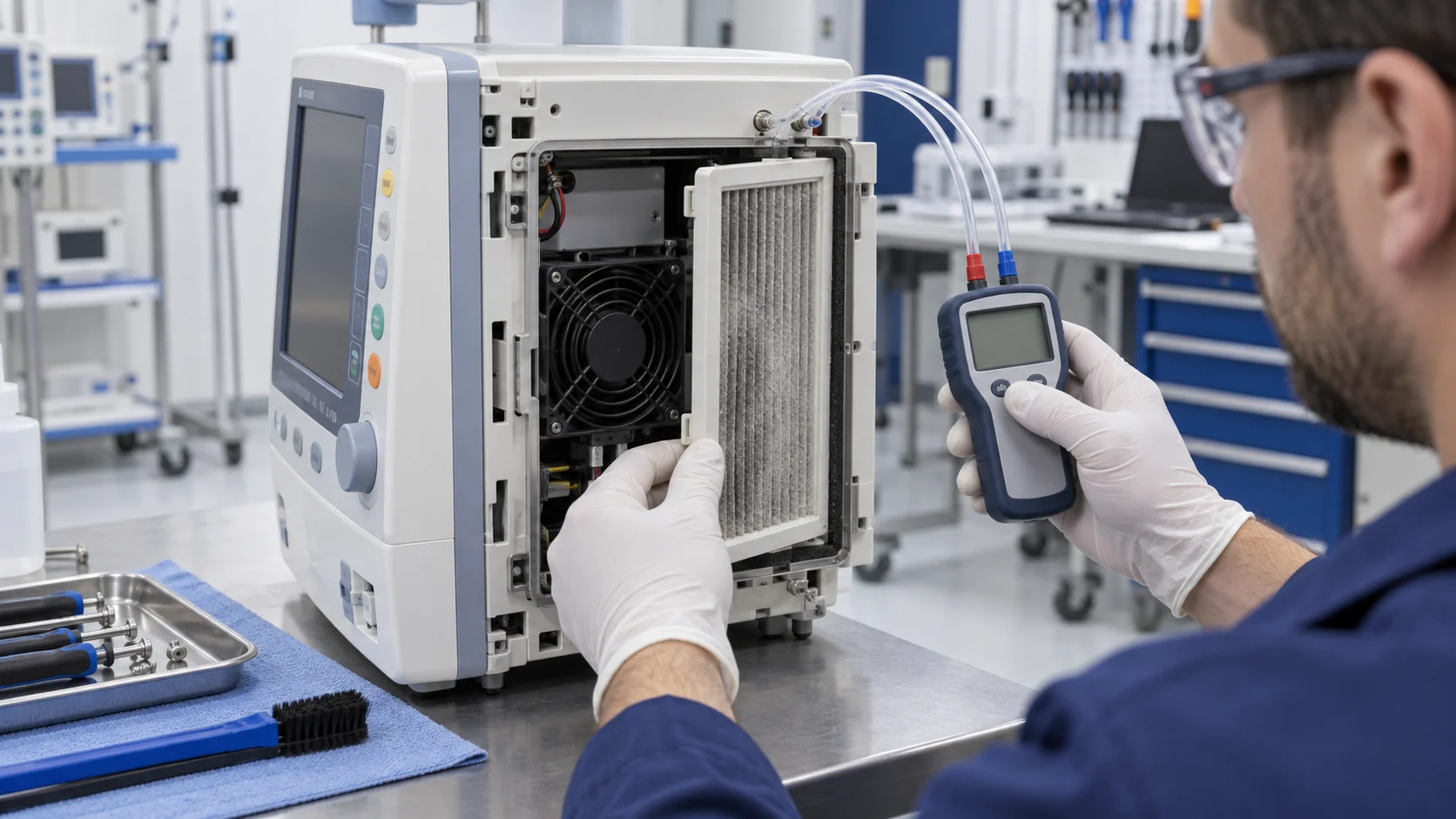
Checkpoint five: validate the air path, not just the fan. The most common selection error in every industry: choosing by free-air CFM. The instant the fan goes behind a grille, a filter, a heatsink, or a convoluted chassis duct, system impedance takes over — and the real operating point is where your measured system curve crosses the fan's P-Q curve. Tight medical enclosures mean high impedance; high impedance means the fan works harder, louder, and hotter than any catalogue number suggests. If that operating point lands in an unstable or inefficient region of the curve, no bearing upgrade and no PWM tuning will rescue the design. Do this math before tooling — it is the cheapest analysis in the entire program and the most frequently skipped.

| Bearing type | Strengths | Watch out for |
|---|---|---|
| Sleeve | Quiet, economical | Life falls quickly as temperature rises |
| Hydrodynamic | Quiet with better temperature resilience | Verify L10 life at your operating temperature |
| Dual ball bearing | Maximum life and high temperature tolerance | Higher noise; confirm the acoustic cost |
Sample validation checklist
Validate the fan in the device, at the duty point — and treat anything unverified as an open risk.
Datasheets describe components. Your device is a system, and in regulated development the validation record is nearly as important as the hardware.

- Noise spectrum — never just dBA — at the real thermal operating point, in an acoustic environment resembling installation. Listen specifically for tones and document the spectrum.
- Effective airflow at the actual system-impedance point, computed from the P-Q curve against your measured system curve — never taken from the free-air headline.
- PWM speed response: stable, monotonic control from maximum down to the minimum duty the system will command. No stall, no hunting, no acoustic surprises at low speed.
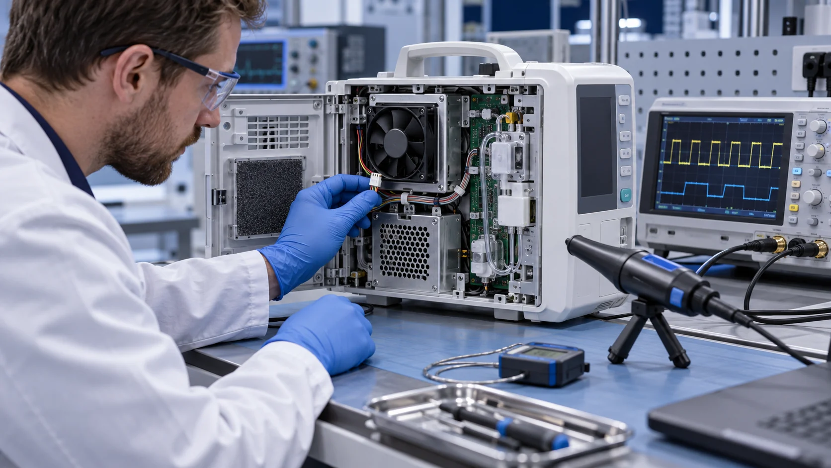
- Locked-rotor and alarm behavior: stall the fan deliberately on the bench and confirm the controller detects it, the alarm annunciates, and the safe state is entered.
- Vibration at the mount: check the enclosure near the fan mount during operation, then measure the transmitted spectrum. Felt vibration is a finding even when accelerometer numbers look acceptable.
- Start, stop, and restart across the full input-voltage range, including brownout recovery and hot restart.
- Disinfection and condensation exposure: wipe-down cycling with the actual agents, plus temperature-transition condensation, followed by functional and acoustic re-check.
- Extended run: 72 hours minimum, continuous, at the worst-case thermal duty — watching current, speed, and hotspot temperatures for drift.
How MEGA Tech supports medical fan projects
Medical fan work is sample-driven: the physics lives in the specific enclosure, mount, and duty cycle.
MEGA Tech works with medical-equipment teams through the full loop: custom cooling fan development and manufacturing, fan selection, airflow-path review, sample validation, and volume production.
A recent example: a European team developing a compact diagnostic instrument came to us with a tonal-noise problem at the normal operating command — discovered on their physical sample, under their mounting and their thermal conditions. The resolution came from iterating speed, mounting, and air path together against that sample, verified by noise-spectrum and thermal measurement, rather than from swapping in a larger catalogue number.
If you are selecting a fan for a medical device, start from the engineering inputs that actually decide the outcome: device type, envelope dimensions, voltage, target airflow and static pressure, noise constraints, bearing and connector preferences, and quantities. Send them through the structured RFQ form or start a conversation on WhatsApp — the earlier the sample loop starts, the cheaper every subsequent decision gets.
Engineer FAQ
Short answers to the questions that come up in every medical fan design review.
Q: Does IEC 60601-1 certify the cooling fan itself? A: No. IEC 60601-1 addresses basic safety and essential performance of medical electrical equipment. The fan is a component whose characteristics must let the complete device satisfy the standard; the device manufacturer remains responsible for the compliance assessment.
Q: Is there a universal dBA limit for medical fans? A: No. Set an installed target for the patient, operator, or bystander position, accounting for background noise, enclosure, duty cycle, and the clinical environment — then verify the spectrum, not just the total.
Q: Should tonal noise be measured separately? A: Yes. Pure tones at blade-pass frequency or motor-whine frequencies dominate perception in quiet rooms. Require the noise spectrum at the real operating point.
Q: Is FG or RD output required? A: Not by name, but the safety architecture needs the controller to detect cooling loss. Specify tachometer or locked-rotor feedback and verify the complete alarm path, including what the system does when the signal asserts.
Q: Which bearing is best for medical devices? A: There is no universal answer. Hydrodynamic bearings balance noise and temperature resilience for many devices; dual ball bearings suit the harshest duties at some acoustic cost. Size the bearing to your temperature and duty, and demand L10 data at those conditions.
Q: Can a catalogue fan replace a custom one by matching frame size? A: No. Equal outline dimensions do not mean equal airflow, pressure, noise, vibration, or life at your operating point. Re-validate the complete installed case whenever the fan changes.
Questions for a design review
Bring these to the review and most medical fan arguments resolve themselves.
- What is the installed noise spectrum at the real thermal duty — and who has listened to it in a quiet room?
- Where does the operating point sit on the P-Q curve against our measured system impedance?
- What happens, step by step, when the fan stalls — and has the complete alarm path been tested?
- What is the L10 life at our internal temperature and duty cycle, with traceable lot records?
- Which disinfection agents and condensation exposures has the sample survived?
- If we change the fan supplier or model tomorrow, which verification records must be reopened?