A European Medical Equipment Customer Came with a Real Sample
The customer did not ask for a louder fan with a larger catalogue number. It needed lower installed noise without losing the cooling margin of a compact medical device.
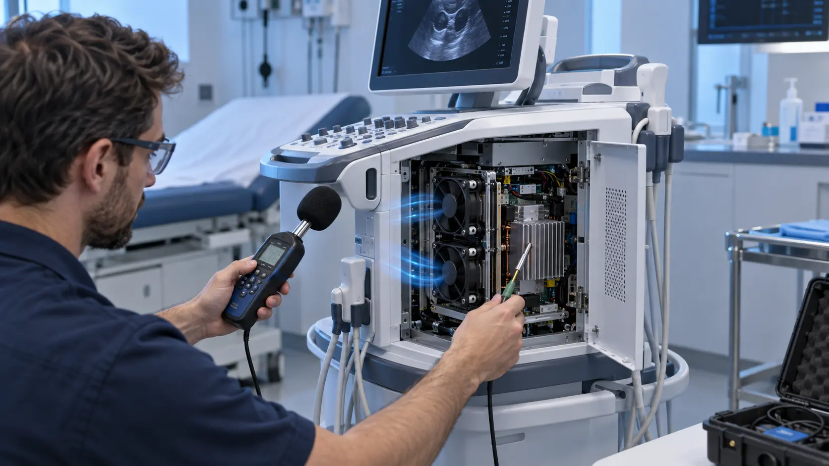
An anonymized European medical-equipment customer was developing a compact diagnostic instrument used close to patients and operators. The prototype used a small DC axial fan behind a grille and heat sink. The device passed its initial thermal check, but the fan produced a noticeable tonal sound at the normal operating command. The sound was more disturbing than the overall A-weighted number suggested, and a light vibration could be felt at the enclosure near the fan mount.
The customer brought the physical sample, fan interface, mounting drawing and observed test condition to MEGA Tech. The requirement was not simply ‘make it quiet’. The device still needed stable electronics temperature, reliable startup, a defined voltage range, acceptable current, compact thickness, repeatable mounting and a service-life assumption. The fan also had to fit a production assembly that could not be redesigned freely.
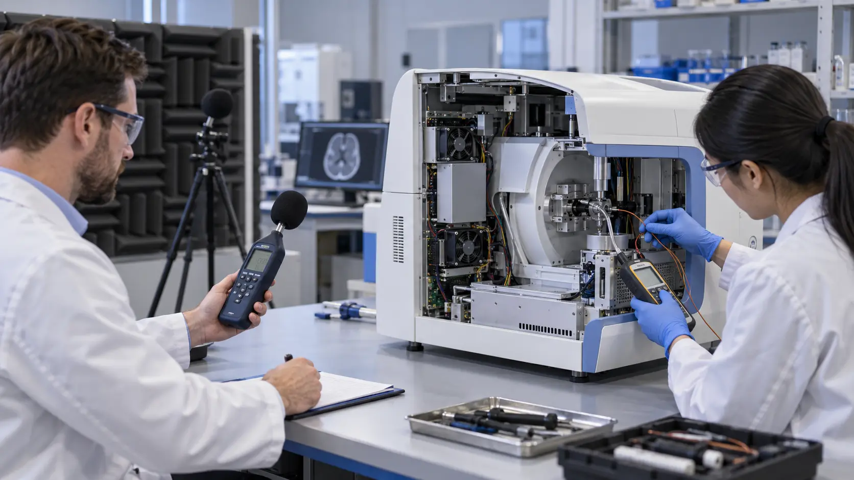
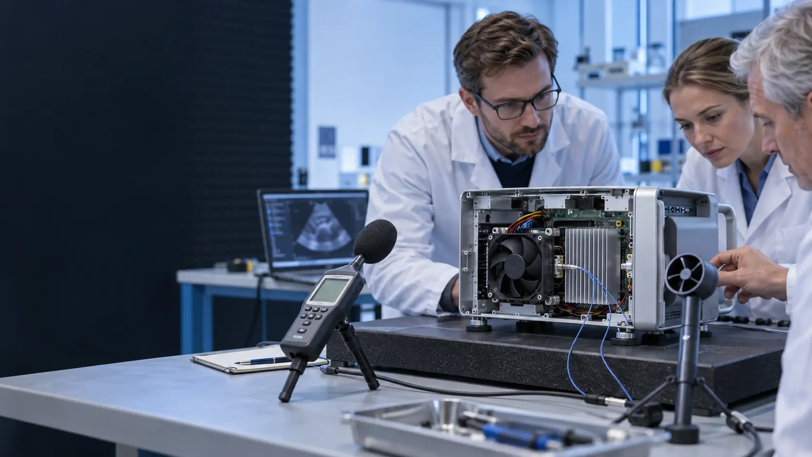
MEGA Tech treated the first customer sample as the reference fixture. The development loop measured airflow or pressure, current, RPM, temperature, noise spectrum and mounting vibration before changing the fan. The exact customer values are confidential; the case describes the engineering process and uses illustrative planning numbers where helpful.
What the Customer Needed to Protect
The design review converted a subjective noise complaint into measurable constraints.
The first constraint was the protected thermal load. The instrument contained a processor board and power electronics that needed a declared inlet temperature and component-temperature margin. A planning example used 10 W of average heat and a 16 W processing peak, with the candidate tested at both states. These values are illustrative, not the customer's released specification. The point was to prevent an acoustic improvement from silently reducing the thermal margin.
The second constraint was the acoustic condition. The customer did not want a comparison between a datasheet dBA value at an unknown distance and a measurement inside the medical enclosure. The team defined the microphone position, room condition, fan command, device mode, mounting and the sound feature that caused the complaint. Narrowband tone, structure-borne vibration and turbulence at the grille were considered separately.
The third constraint was the mechanical interface. The fan envelope, screw or sleeve mounting, cable exit, connector, grille free area and heat-sink position were already linked to the sample. A thicker fan could improve pressure capability but might collide with the board or reduce service access. A softer mounting sleeve could reduce structure-borne noise but change alignment. Every proposed change had to be checked against the real assembly.
| Requirement | Sample evidence | Why it matters |
|---|---|---|
| Thermal | load power, inlet temperature and protected component temperature | prevents a noise fix from reducing cooling margin |
| Acoustic | dBA, spectrum, microphone position and fan command | separates broadband noise from a disturbing tone |
| Mechanical | envelope, grille, sleeve, clearance and cable exit | keeps the revised fan compatible with the device |
| Electrical | voltage, PWM/voltage command, current and feedback | prevents interface and startup problems |
| Reliability | duty cycle, bearing temperature and service-life assumption | connects the sample to production use |
Sample 01: The Catalogue Replacement Was Not the Final Answer
The first comparison showed why the same frame size does not guarantee the same installed acoustic or thermal result.
The customer initially compared a replacement fan with the same nominal outline dimensions. On the bench, the replacement appeared acceptable. In the device, however, the tonal character changed and the outlet pressure interaction produced a different noise signature. The fan still rotated normally, but the grille, heat sink and enclosure created a system effect that was not represented by the free-air comparison.
The team measured the operating command, RPM, current, installed pressure or airflow proxy, inlet temperature, protected component temperature and acoustic spectrum. It also checked the mounting interface and the clearance between fan, grille and surrounding structure. A planning example showed the trade-off: if the device requires 12 CFM at 3 mmH2O, a fan that reaches 20 CFM in free air is not automatically better than one that delivers the required duty more quietly at the installed resistance.
The baseline record gave the customer a shared language. Instead of saying ‘the new fan is noisy’, the team could identify a narrowband peak, its command range, the mounting surface involved and the thermal state in which it appeared. That made the next sample adjustment specific and testable.
Sample 02: Tune Speed, Mounting and Air Path Together
The second revision addressed the source of the sound while keeping the actual cooling duty visible.
MEGA Tech reviewed the fan blade behavior, speed range, mounting stiffness, sleeve or isolation interface, grille opening and heat-sink restriction. The objective was not to suppress every vibration by adding a soft part. A mount that is too soft can allow movement, cable contact or a change in the inlet gap. The revised sample therefore checked mechanical support, alignment and clearance at the same time as the acoustic measurement.
The control curve was also adjusted. A fixed high command kept temperature stable but created more tonal energy than necessary during low load. A lower command reduced sound but needed reliable startup and enough pressure margin when the processor entered its peak mode. The candidate was tested at minimum stable speed, normal operation, peak processing and warm restart. PWM or voltage behavior was recorded with current and RPM rather than assumed from the signal label.
The air path was kept constant during the comparison. The same grille, heat sink, enclosure panel and microphone position were used. This is important because moving a fan or opening a panel can make a noise improvement appear larger than it really is. The customer could then distinguish a fan change from an installation change.

Sample 03: Verify Noise at the Real Thermal Duty
A quiet idle measurement is not enough when the medical device spends part of its cycle at a higher thermal load.
The customer repeated the comparison across the device cycle: idle, normal measurement, peak processing and post-peak recovery. At each state the record included fan command, RPM, current, protected temperature, pressure or airflow proxy and acoustic spectrum. The purpose was to catch a common failure mode: a fan sounds quiet at idle, then enters a strong tonal band at the command needed to protect the load.
The team also checked the enclosure surface and nearby structure. A fan can be aerodynamically acceptable while its vibration travels through a panel or bracket. Conversely, an acoustic liner or soft mount can reduce the measured sound while increasing inlet restriction. The sample was not accepted on the basis of a single dBA value; it needed a repeatable balance between cooling, noise, vibration and power.
The project used a short repeated run and a longer duty-cycle run. The short run made sample comparison efficient. The longer run checked warm-up, bearing temperature, control stability and whether the acoustic character changed as the enclosure heated. This is the kind of evidence a medical-equipment engineering team can carry into its own device validation plan.
The Release Sample Was Defined by the Customer Interface
The final result was a controlled sample configuration, not a promise that one fan model fits every medical device.
After the revision loop, the customer had a candidate fan interface and an acceptance record tied to the actual enclosure. The selected configuration was checked for voltage, command response, startup, current, RPM, airflow or pressure, protected temperature, noise spectrum, vibration and mounting repeatability. The final values remain project-specific and are not presented as a universal MEGA Tech product rating.
The transferable lesson is that medical equipment noise is a system property. Fan diameter, blade geometry, speed, pressure, grille, heat sink, enclosure panel, mount and control curve all contribute. A supplier can reduce the time required to converge the fan sample, but the device maker still has to complete the medical risk, EMC, safety, cleaning and production validation work.
For a startup or a new instrument platform, the process can start with a small sample quantity. The customer can change the mount, duct or control settings, return the evidence, and ask MEGA Tech to adjust the next sample. Once the device team approves the behavior, critical dimensions and test conditions can be frozen for a controlled production configuration.
How MEGA Tech Supports Medical Fan Customization
MEGA Tech works with the customer's sample and installed operating point, from first prototype through production-ready fan configuration.
MEGA Tech develops custom DC axial fans and compact centrifugal blowers for medical and laboratory equipment where low noise, airflow, static pressure, temperature, control and reliability must be balanced. We can review frame and thickness, airflow direction, pressure/airflow duty, connector and cable, PWM or voltage control, FG or RD feedback, bearing configuration, startup behavior, mounting, sleeve or isolation requirements and the sample-level acoustic condition.
For a useful first review, provide the device sample or drawing, heat load, airflow and static pressure at that airflow, inlet temperature, voltage range, control interface, connector, envelope, grille or heat-sink information, microphone position, noise target, vibration concern, duty cycle and life assumption. If the current fan is a Sanyo Denki, SUNON, Delta, NMB or ebm-papst part, include the installed working point and noise problem rather than relying only on its part number.
We can accompany the customer through sample revisions and provide fan-side measurements for the declared states. We do not supply medical controllers, clinical validation, EMC certification, infection-control procedures, cabinet safety design or final regulatory approval. The medical device manufacturer owns the complete device risk and release decision.
Engineer Questions About This Medical Fan Case
Use these questions when a customer asks for a quieter fan or a replacement sample.
Q: Why not compare only the dBA value? A: Because distance, installation, command, room and frequency spectrum change the result. A narrowband tone or structure-borne vibration can be more important than the overall number.
Q: Can a softer mounting sleeve solve the problem? A: It may reduce structure-borne sound, but it can also change alignment, clearance and inlet restriction. Validate support and airflow together.
Q: What did MEGA Tech customize? A: The fan duty, control response, connector, cable, mounting, thickness and sample configuration can be reviewed around the customer's device.
Q: How do you keep the cooling margin during a noise reduction? A: Compare noise and protected temperature at the same installed pressure, load state and fan command range.
Q: Is this a medical certification case? A: No. It is an anonymized engineering case pattern. The device manufacturer owns medical safety, EMC, risk management and final approval.
Questions for a Medical Fan Sample Review
A short checklist helps move from a noise complaint to an actionable custom-fan requirement.
- What is the protected heat load in idle, normal and peak device modes?
- What airflow and static pressure are required at the actual grille and heat sink?
- What sound is objectionable: broadband level, tonal peak, vibration or panel resonance?
- Where is the microphone, and what measurement method and room condition are used?
- What are the voltage range, PWM/voltage command, minimum startup and feedback requirements?
- What are the fan envelope, mounting, sleeve, cable exit and service-access limits?
- What temperatures and acoustic states must be checked after warm-up?
- What bearing life and duty cycle are required in the actual ambient condition?
- Which values are fan-side evidence and which require complete medical-device validation?
- Which sample dimensions and test conditions will be frozen for production?