The Analyzer Passed the Bench Test and Missed the Quiet Room
An anonymised small medical-equipment team needed a custom cooling fan for a compact analyzer moving from engineering prototype toward pilot production.
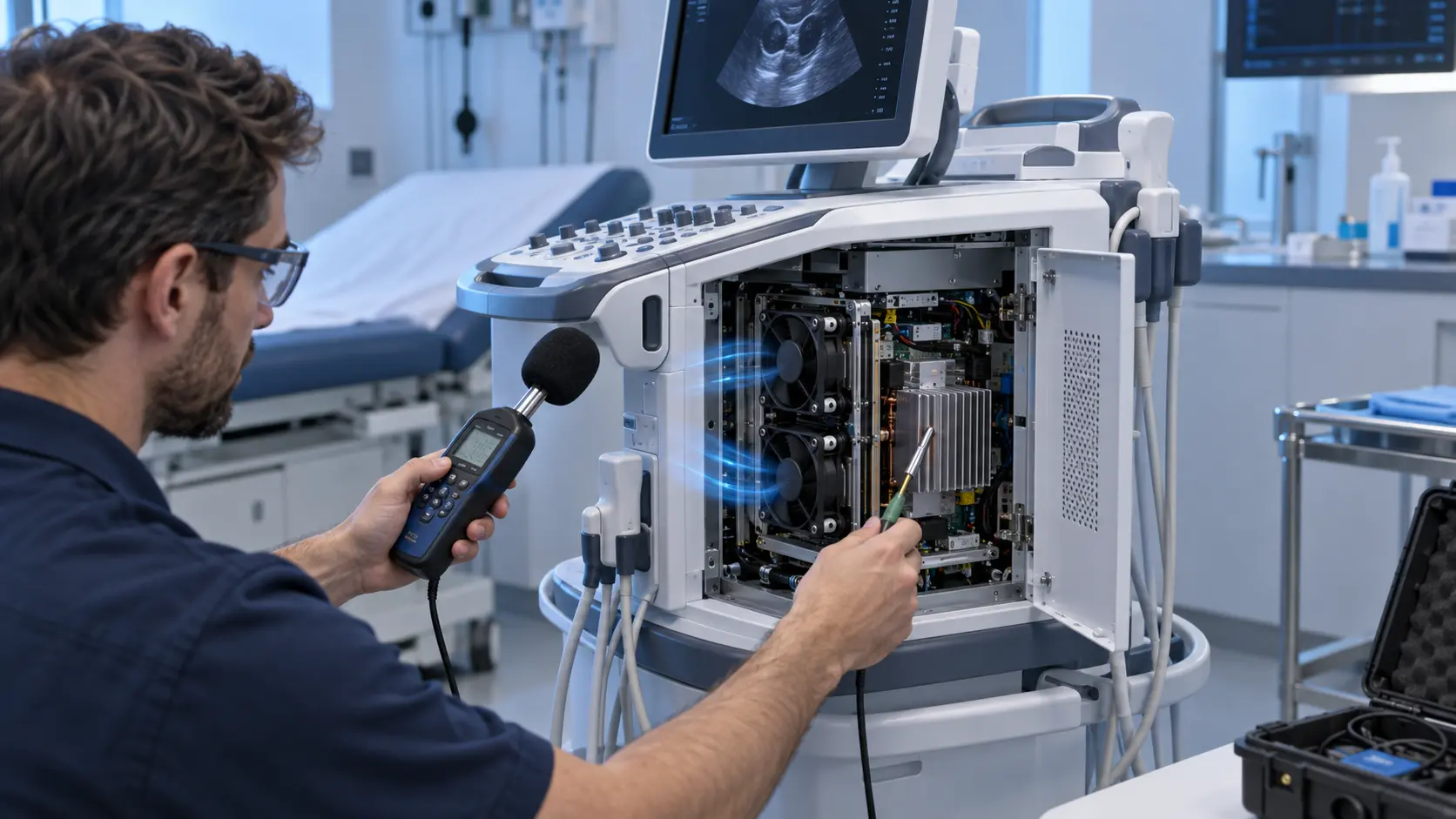
The first prototype used an open heat sink and a fan on a temporary bracket. Thermal performance was acceptable, but the product was intended for a quiet room where tonal noise, panel vibration and service access mattered as much as average temperature. Once the cover, filter, cable harness and acoustic panels were installed, the sound character changed and the useful airflow through the electronics was less obvious.
The project therefore combined thermal, acoustic, mechanical and production questions. The team needed a fan that could be selected at the installed operating point, mounted without transmitting vibration into the enclosure, controlled consistently and installed the same way on pilot units. A catalogue noise number or matching outline dimensions could not answer all four questions.
Customer identity and measured acceptance values remain confidential. This is an anonymised engineering case pattern, not a medical certification claim or a universal performance guarantee. The medical system owner remains responsible for the complete product qualification and safety program.
Define the Analyzer Heat States Before Choosing the Fan
The limiting condition may be a long measurement cycle, a short warm-up event or a service restart rather than an average operating temperature.
The design review listed the electronics that release heat, their duty states and the intended inlet-temperature basis. The analyzer could have standby, warm-up, measurement, data-transfer and shutdown states. The team identified where the thermal decision was made: an electronic component, a heat sink, a power supply area or the air leaving the enclosure.
Sensors were placed at the fan inlet, limiting electronics, heat sink and outlet. Fan voltage, current, command and actual RPM or FG/RD feedback were recorded with the thermal channels. This showed whether a temperature rise followed heat load, a warm inlet, a control transition or a restriction in the installed air path.
The first record did not pretend to be a final specification. It separated measured values from assumptions and made clear which condition still required a representative enclosure. That prevented a quiet bench test from becoming an unsupported production promise.
| Input | Why it matters | Evidence |
|---|---|---|
| Heat state | Identifies the limiting thermal condition | Time-aligned load and temperature record |
| Inlet condition | Sets cooling margin and acoustic context | Sensor position and room basis |
| Installed resistance | Moves the fan operating point | Filter, grille and heat-sink pressure record |
| Interface | Changes speed and fault feedback | Voltage, PWM, FG/RD and connector record |
| Noise position | Makes the result repeatable | Defined microphone and enclosure state |
Select Airflow at the Installed Pressure
A compact medical enclosure can lose useful airflow through filters, narrow openings, acoustic treatment and cable bypass.
The team mapped the path from inlet grille to filter, fan, heat source and outlet. It checked whether acoustic material blocked the inlet, whether the cable bundle narrowed the path and whether hot exhaust returned to the inlet. Pressure and airflow points were selected before comparing fan samples so that the test boundary stayed consistent.
A free-air airflow value was treated as a reference, not an installed result. The candidate was compared on the fan and system curves at the enclosure condition. A direct axial path and a turning or restrictive path could require different fan-side approaches. The final choice remained conditional on envelope, voltage, control, noise, vibration and measured airflow at the heat source.
The team also recorded the reference condition for airflow and the exact filter state. Pressure across a filter, pressure across the fan and pressure across the whole enclosure are different measurements. Naming the boundary prevented later procurement or service comparisons from mixing incompatible data.
The review sheet also stated whether the airflow target was a minimum at the electronics, a nominal value at the fan outlet or a total enclosure exchange rate. Those descriptions are not interchangeable. A sample that looks strong at the outlet may deliver less useful air after a fine filter and a narrow return path. Recording the measurement plane made the fan comparison meaningful and gave the equipment team a practical acceptance point for the next build.
Altitude and room temperature were kept visible in the test record instead of being hidden in a general environmental note. Air density changes the relationship between volume flow, pressure and heat removal, while a warm room reduces available thermal margin. The team did not convert these observations into a universal derating claim; it used them to define which analyzer states and environmental boundaries the sample review actually represented.
Prototype Sample One: Separate Airflow Noise From Tonal Noise
The first sample was used to find whether the complaint came from broadband airflow, a motor tone, blade interaction or a vibrating panel.
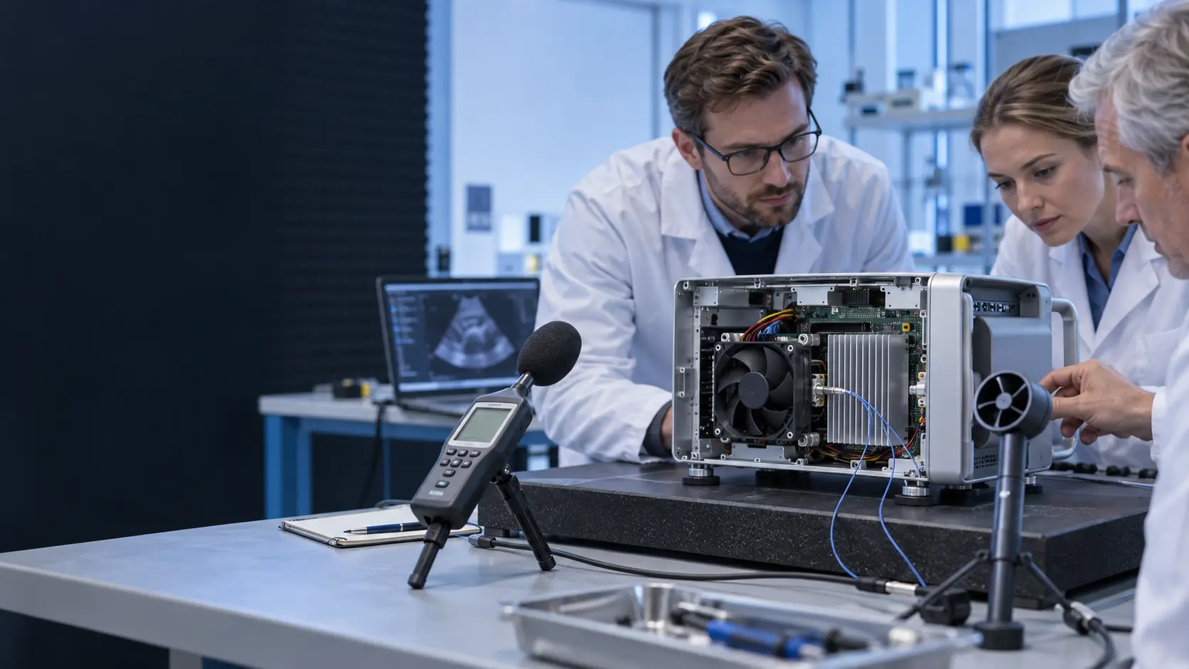
The sample was installed with the intended bracket, cover, grille and cable route. The team measured sound at a defined position and operating state while also recording airflow, pressure, temperature and RPM. A lower sound level was not accepted if it resulted from less useful air through the heat source.
The acoustic review compared fan speed, PWM transitions and enclosure panels. A grille or cavity can amplify a tone that is not obvious in free air. A bracket can transmit vibration into a cover. A cable can bridge an isolator. The team changed one variable at a time so that the next sample had a clear purpose.
The result was a shortlist of fan-side and enclosure-side actions: change the fan operating band, adjust the mounting interface, revise the cable exit, alter the inlet treatment or review the air path. The customer system team retained ownership of the complete acoustic acceptance method.
Each action was tied to an observation rather than a preference. If a tone appeared only after the cover was installed, the cover and cavity were reviewed before changing the fan. If vibration followed a bracket preload change, the interface was investigated before declaring the motor or bearing responsible. This kept the prototype discussion evidence-led and reduced the risk of solving an enclosure problem by selecting an unnecessarily aggressive fan.
The team also checked whether the quietest condition had sacrificed cooling margin. Acoustic work can produce a misleading improvement when the controller reduces speed below the useful operating point or when a partially blocked inlet changes the sound without fixing the heat path. The approved candidate therefore had to satisfy the defined thermal state, pressure boundary and restart behavior at the same time as the acoustic target.
Prototype Sample Two: Tune PWM, Feedback and Restart
Quiet operation is useful only when the fan starts reliably and still delivers the required cooling during the analyzer duty.
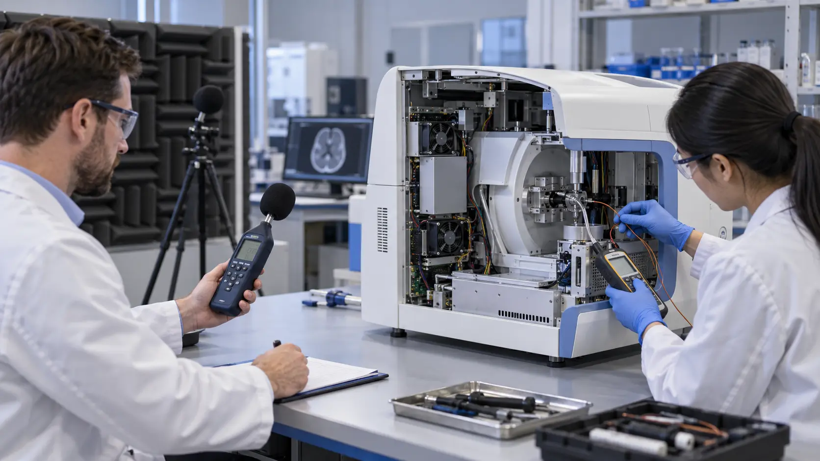
The controller schedule used a stable low-speed region, a normal operating band and a response for the highest thermal state. PWM percentage was not treated as a universal RPM value. Actual speed, airflow, pressure, current and temperature were correlated at the supplied voltage and enclosure condition.
FG or RD feedback was checked at startup and steady operation. The analyzer controller defined what counted as a valid signal and what it would do after a missing or delayed signal. A fan-side feedback trace did not replace system-level fault handling, electrical safety, EMC or medical-equipment qualification.
Cold start, warm restart, brief power interruption and repeated measurement cycles were included in the sample review. The team recorded whether the fan returned to a valid operating state without creating a new acoustic event or a thermal overshoot.
The restart record included the command sent by the analyzer, the measured supply at the fan connector and the timing of the feedback signal. This distinction matters when a controller reports a fan fault: a delayed command, a voltage drop in the harness and a genuine fan start issue can look similar in a high-level log. The sample review gave the system team enough detail to decide which layer needed correction.
Speed control was also checked across the transitions that occur during a real measurement cycle, not only at a convenient fixed PWM value. The team watched for audible steps, hunting, delayed feedback and temperatures that continued rising after the command had increased. A stable control schedule was treated as part of the cooling assembly, because a nominally suitable fan can behave differently when the installed controller changes its duty pattern.
| Check | Risk if missed | Pilot evidence |
|---|---|---|
| Low-speed start | Fan stalls or feedback arrives late | Supply, command and start trace |
| PWM transition | Tone or vibration appears during control change | Speed, sound and temperature trace |
| FG/RD feedback | Controller misreads a healthy or failed fan | Signal and system response record |
| Mounting | Panel becomes an acoustic radiator | Clearance, preload and vibration check |
| Power interruption | Analyzer restarts without cooling margin | Repeat restart and recovery record |
Build the Pilot Around Clean Assembly and Service Access
The pilot unit must preserve the tested air path when an operator installs, services or replaces the fan.
The pilot used the intended connector, harness length, fasteners, gasket, filter, cover and service sequence. The work instruction stated airflow direction and mounting orientation. It also showed the cable route and clearance so that an operator could not unknowingly close an inlet or create a bypass.
Inspection focused on connector seating, frame clearance, bracket condition, filter position, gasket compression and cable retention. These details were selected because they could move pressure, airflow, noise or vibration. Thermal and acoustic checks were repeated on representative pilot units rather than relying on the first prototype.
Service replacement was part of the design review. A replacement fan should not require a different cable route, distort the frame or disturb an acoustic isolator. If a new supplier or voltage variant changes any of those details, the request returns to engineering for a new sample decision.
The work instruction used photographs or simple orientation marks to show the intended airflow direction and connector exit. It identified surfaces that must remain clear and stated which gasket or isolator had to be reused. These small controls helped preserve the tested pressure drop and prevented a service action from turning into an unrecorded mechanical change. The aim was repeatable assembly, not a claim that every replacement is automatically equivalent.
Pilot feedback was reviewed with manufacturing and service teams before the specification was frozen. Questions about screw access, harness slack, filter seating and cleaning access were treated as design inputs. If an operator could reasonably install the fan in two different orientations, the drawing or work instruction needed clarification before release.
Freeze the Fan Specification Without Overclaiming Qualification
A production specification should document the tested fan-side boundary and leave system qualification with the medical-equipment owner.
The release record captured fan envelope, voltage tolerance, current, installed airflow and static pressure, control interface, connector, mounting, noise target, temperature and environment. It recorded sensor and microphone positions, filter condition, analyzer state and the enclosure configuration used for the result.
Change triggers were listed before volume production: new grille, filter, acoustic panel, cover, heat source, controller schedule, connector, cable route, bracket, ambient range or service orientation. These changes might require a new fan sample even if the frame size remained unchanged.
The fan manufacturer can provide fan-side data and sample evidence. The medical-equipment developer and system integrators remain responsible for the complete product design, electrical safety, EMC, clinical or laboratory workflow, risk management and final qualification.
The final record separated three kinds of evidence: catalogue information, sample measurements and system acceptance results. Catalogue information helps create a candidate list. Sample measurements show behavior at the supplied voltage and test setup. System acceptance asks whether the complete analyzer meets its thermal, acoustic, electrical and workflow requirements. Keeping those layers separate made the approval language more accurate and easier to update when the enclosure changed.
The change-control list was intentionally practical. A new filter grade, grille opening, heat source, controller, cable harness, bracket or service panel can move the operating point or alter the acoustic path. The team agreed that such changes should trigger an engineering review before a production substitution, even when the fan outline and nominal voltage appear unchanged.
How MEGA Tech Supports Custom Medical-Equipment Fans
MEGA Tech helps equipment teams move from a thermal and acoustic requirement to a fan sample measured in the real enclosure.
MEGA Tech develops and manufactures custom cooling fans, covering fan selection, air-path review, sample validation and volume production. We can review DC axial fan and centrifugal blower options against installed airflow and static pressure, with attention to noise, vibration, voltage, control, connector, mounting and environmental conditions.
For a first review, send heat load by state, inlet temperature, airflow and static-pressure target, fan envelope, voltage tolerance, PWM/FG/RD or alarm interface, connector, mounting, noise position and target, environment, quantity and life assumption. A representative enclosure, airflow drawing or current fan sample makes the first review more useful.
MEGA Tech is the custom cooling-fan manufacturer. Complete medical equipment, coils, liquid loops, controllers, electrical safety, EMC, clinical qualification and system risk management remain with the equipment developer and system integrators. Start with the fan selection tool, review the DC axial fan range, or request a sample on WhatsApp.
For a small equipment team, the useful starting point is not a generic promise of a quieter fan. It is a compact engineering brief that identifies the installed pressure, the required useful airflow, the envelope, the voltage and the control behavior. MEGA Tech can then discuss a candidate family, review the air path and prepare a sample direction for testing on the customer's analyzer. The result remains subject to the customer's measurement method and complete product approval.
A sample request can also state what must remain unchanged from the current prototype: connector position, mounting holes, airflow direction, service access, noise boundary or controller interface. Calling out those constraints early helps distinguish a true customization need from a simple catalogue substitution. It also gives the equipment team a clearer basis for comparing samples during prototype and pilot reviews.
Engineer FAQ
These questions usually decide whether a medical-analyzer fan sample is ready for pilot production.
Q: Is a low free-air noise number enough? A: No. Check installed airflow, pressure, enclosure panels, filter condition, mounting and the defined microphone position.
Q: Can the fan run slowly all the time? A: Only after startup, airflow, pressure, thermal margin, feedback and acoustic behavior are validated at the supplied voltage.
Q: Does fan-side data equal medical-equipment qualification? A: No. The equipment developer owns complete product safety, EMC, risk management and final qualification.
Q: What should I send for a custom sample? A: Send heat load, airflow, static pressure, inlet temperature, envelope, voltage, control, connector, mount, noise target, environment and quantity.
Q: Can a pilot change trigger another sample? A: Yes. A new filter, grille, cover, acoustic treatment, controller, cable route or mount can change the installed result.
Questions for a Medical-Equipment Fan Design Review
Use this checklist with thermal, acoustic, mechanical, electrical, manufacturing, service and quality teams.
- Which analyzer state defines the limiting heat load?
- What airflow and static pressure are required after the filter, grille, acoustic treatment and outlet are installed?
- Where are the fan inlet, electronics and outlet temperatures measured?
- What voltage tolerance and control interface exist at startup and steady operation?
- What PWM, FG/RD or alarm behavior defines a valid fan state?
- Can the bracket, cable, grille, filter or cover create bypass, contact or vibration transfer?
- What microphone position and analyzer state represent the finished equipment?
- Which assembly and service details must be repeated on every pilot unit?
- Which change triggers a new sample: fan, filter, grille, cover, controller, cable or mount?
- What exact information should accompany a sample request: size, voltage, airflow, pressure, quantity and environment?