The Ultrasound System Was Thermally Stable but Too Noticeable in the Room
An anonymized European medical-equipment developer needed a quieter cooling-fan sample for a portable ultrasound platform used in a clinical examination room.
The existing fan removed enough heat during a short bench test, but its tonal noise and panel vibration became noticeable during a long scan. Lowering the fan command reduced the sound, yet the power module and processing board approached their temperature limit when the system operated continuously.
MEGA Tech reviewed the customer's device sample, heat sources, fan envelope, acoustic target, airflow path, vibration mounting, voltage and control interface. The task was not simply to find the quietest fan. It was to develop a sample that balanced installed airflow, low-speed noise, vibration transmission, electrical behavior and long-duty reliability.
The customer identity and released acceptance values remain confidential. The case describes the engineering workflow and uses illustrative calculations where customer measurements cannot be disclosed.
The Engineering Hook: Quiet Cooling Is a System Requirement
A medical fan can be quiet on a datasheet and still become audible after the grille, duct and chassis are installed.
Medical equipment design teams often need to control more than temperature. The fan can contribute aerodynamic noise, motor or bearing noise, blade-pass tones, panel vibration and electrical disturbance. Ultrasound electronics also have sensitive signal and power paths, so thermal and EMI decisions can interact.
Eaton's medical thermal-management guidance highlights noise, vibration, dust, shock and liquid ingress as system considerations. Analog Devices' ultrasound power-design discussion likewise treats noise, EMI and thermal dissipation as linked design concerns. These references support a practical rule: fan selection should be made at the device operating point and then verified in the complete chassis.
The developer therefore set two goals: maintain the limiting electronics below the approved temperature boundary and avoid unnecessary high-speed operation during quiet examination periods. The final fan command was part of the product behavior, not an afterthought.
The Problem in Operation: Fan Noise Was Being Amplified by the Chassis
The sound source was not only the impeller. The inlet grille, narrow duct and thin panel created additional turbulence and structure-borne noise.
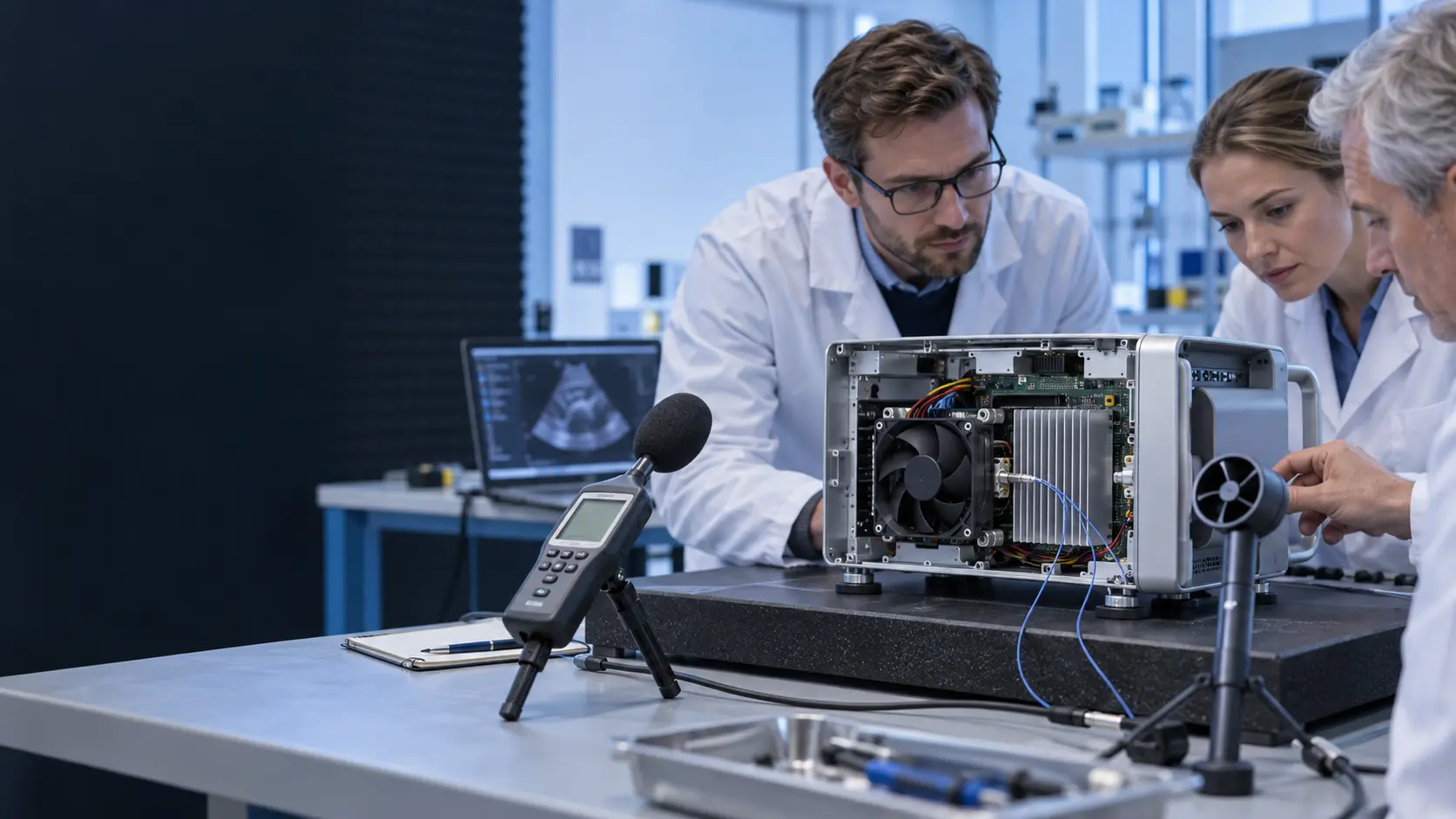
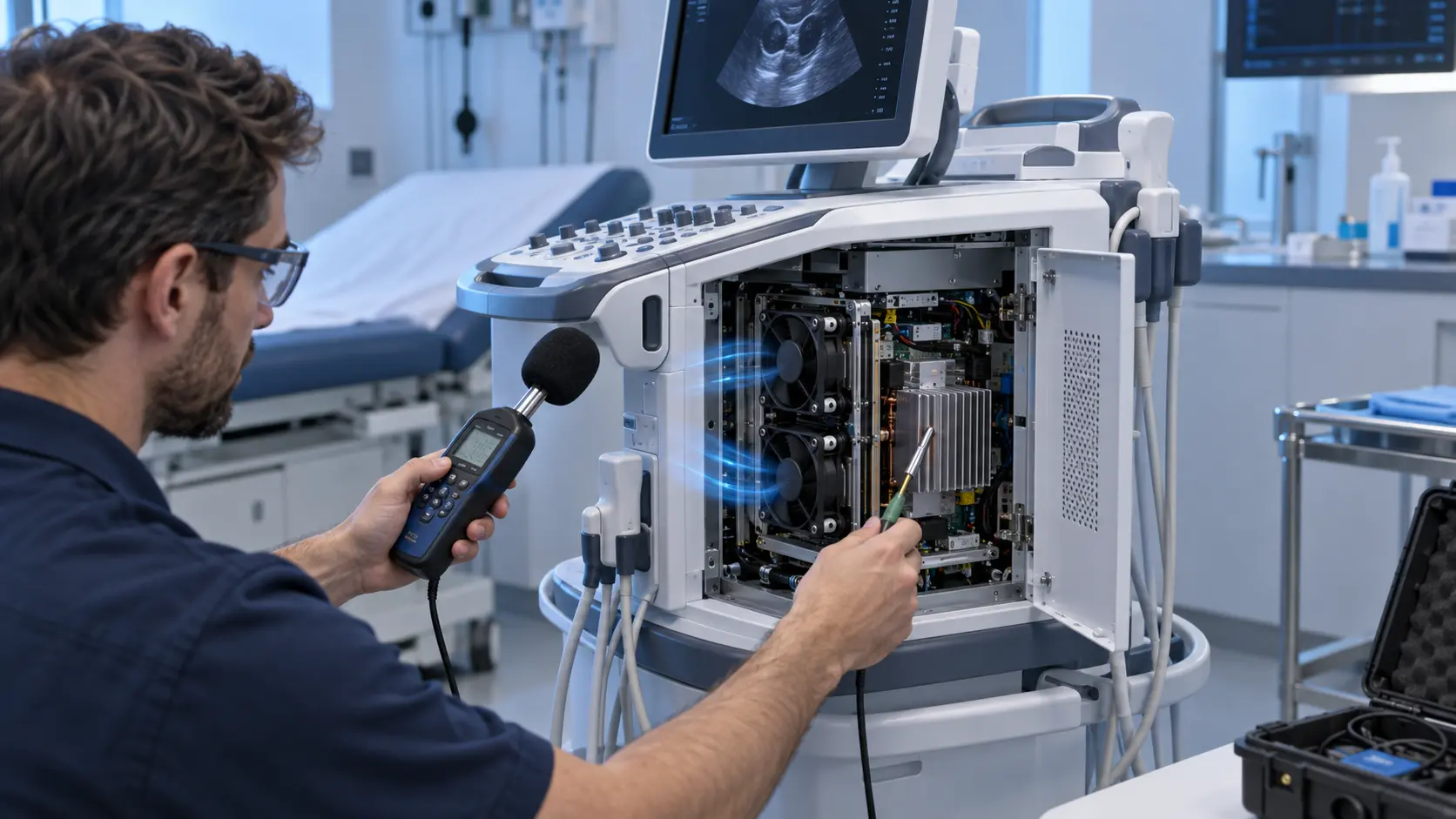
The first review measured the device at idle and high processing load. A-weighted sound pressure alone did not explain the complaint, so the team separated broadband airflow noise, tonal blade-pass content, motor or bearing noise and vibration at the chassis panel. The same fan speed sounded different after the air path was assembled.
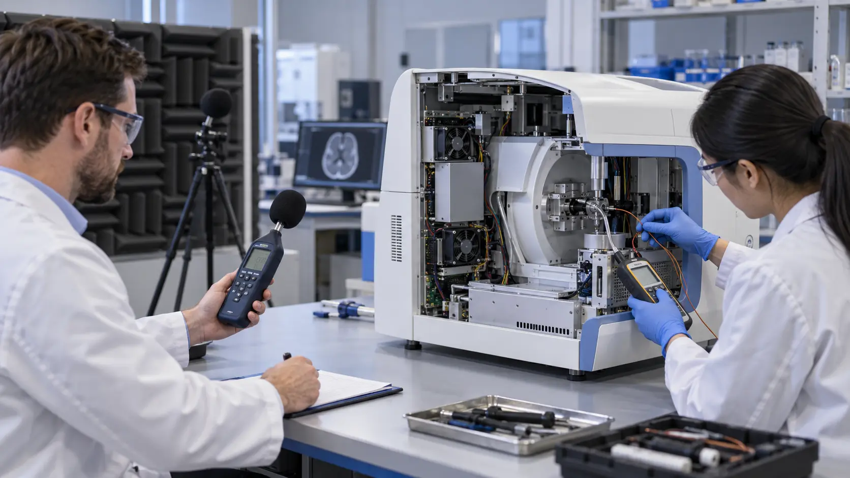
The acoustic map was taken at the operator position and beside the device. Temperature probes were placed at the power supply, processor area, transducer electronics and fan inlet. This prevented a quiet result from being accepted if it came from moving too little air through the limiting zone.
The team also checked whether PWM switching or fan commutation introduced a signal disturbance near sensitive measurement periods. The final compliance program remained the medical-device developer's responsibility; MEGA Tech focused on fan-side behavior and sample integration.
Interactive: Watch Quiet Mode and Thermal Mode Use Different Fan States
The animated schematic shows why one fixed fan speed is rarely ideal for both a quiet examination and a high-processing thermal load.
The figure is qualitative, not CFD or an acoustic test. It shows two control states: a lower-noise examination mode and a higher-airflow processing mode. The actual device should use approved temperature sensors, command limits and risk controls rather than copying the illustrative settings.
The validation sequence used idle, quiet scan, long scan, maximum processing and restart states. Each state recorded fan voltage, current, PWM, RPM or FG, component temperatures, sound pressure, vibration and any relevant system signal. The team also checked the transition between states so a sudden full-speed step did not become a new user complaint.

Sample 01: Start With the Customer Chassis and the Limiting Heat Source
The sample was developed from the actual portable system because the available space and air path were more restrictive than the fan catalogue suggested.
The developer supplied the fan opening, duct section, grille, heat-source list, allowable temperatures, voltage tolerance, connector, acoustic measurement position and vibration mounting. MEGA Tech reviewed compact axial and centrifugal options, including thickness, pressure capability, bearing choice, FG/RD feedback and PWM behavior.
As an illustrative estimate, suppose the device must reject 120 W while allowing a 12 K average air rise. Qv = P/(rho x cp x deltaT) gives approximately 0.0083 m3/s, or about 17.6 CFM, before accounting for the installed pressure drop and local hot spots. If only 14 CFM reaches the limiting electronics, the same simplified heat balance predicts an average rise of about 15 K. These values are planning estimates, not clinical or product acceptance limits.
The sample review also checked fan inlet clearance, grille open area, cable movement, acoustic panel resonance, service access and the possibility that the fan would pull dust toward an optical or sensitive measurement area. The fan was not treated as an isolated component.
Sample 02: Tune the Fan for the Operating Point, Not Maximum RPM
The quiet-mode target was achieved by controlling unnecessary speed while keeping enough pressure margin for the real duct and grille.
The candidate sample was tested at the installed pressure and at the actual supply voltage. The control curve retained a minimum protective command, a low-noise examination band and a high-processing response. Hysteresis prevented rapid speed changes near the temperature threshold.
The team compared the original and candidate fan at equal thermal duty rather than equal RPM. It recorded sound pressure, tonal peaks, vibration and current at each point. If a lower noise value came from a lower airflow, it was not accepted as a thermal improvement.
A simple electrical check was included. A 24 V fan drawing 0.28 A uses about 6.7 W; at 0.45 A it uses about 10.8 W. These are illustrative values only. The selected fan's actual current and the medical equipment's power budget must control the final specification.
Sample 03: Validate Vibration, EMI and Long-Duty Restart
The medical-device sample needed to remain quiet and stable after repeated operation, not only during the first minutes of a demonstration.
The fan mount was checked for vibration transfer into the chassis and nearby electronics. The team compared rigid and compliant mounting directions and checked whether the panel or duct amplified a narrow tonal component. The chosen mounting was evaluated with the cover, grille and cable routing installed.
The electrical review checked PWM frequency, FG waveform, locked-rotor or RD behavior and supply transients during start. The equipment developer then performed its required EMC and safety assessments. MEGA Tech did not claim that a fan alone provides IEC 60601 compliance; the fan is one component in the product's risk and qualification program.
Long-duty operation included repeated warm restarts, quiet-mode transitions and a controlled fan-fault response. The sample report recorded the conditions so the buyer could compare future lots or replacement candidates against the same evidence.
Validation Result: A Custom Sample Reduced Interference Without Hiding Thermal Risk
The final sample gave the developer a documented tradeoff between thermal margin, acoustic behavior, vibration and fan power.
The transferable result was not a universal dBA claim. It was a repeatable system-level validation method. The fan was compared at the installed operating point, the limiting component temperature was measured directly and the acoustic result was separated into airflow, tonal and structure-borne contributions.
The production release package documented the fan P-Q curve, voltage range, PWM/FG/RD behavior, sound test position, vibration mounting, current, temperature rating, bearing or life assumption, material information and sample test conditions. The medical-device developer remained responsible for final safety, EMC, risk management, usability and regulatory documentation.
For procurement, this makes a custom or brand-alternative fan easier to evaluate. The right replacement is not the quietest component in free air; it is the sample that preserves the installed thermal duty and user environment.
How MEGA Tech Supports Medical-Equipment Fan Customization
MEGA Tech develops fan samples around the medical device's real heat load, air path, acoustic target and mechanical envelope.
We can review compact axial or centrifugal options, low-noise operating points, PWM and FG/RD signals, connector and lead-wire details, bearing and life targets, vibration mounting, material and documentation requirements, voltage tolerance and small first-build quantities. We can also evaluate alternatives to Sanyo Denki, SUNON, Delta, NMB, ebm-papst and other installed brands when the operating point is defined.
Please provide the device heat load, limiting component temperature, fan opening, pressure path, voltage, control interface, acoustic target, vibration sensitivity, service environment, quantity and required documentation. If data is incomplete, send the current fan part number, device photos and any measured temperature or sound points.
Our scope is fan and air-path engineering, sample customization and comparative validation. The medical-device manufacturer remains responsible for final IEC 60601, EMC, risk-management, biocompatibility and market approval decisions.
Engineer Questions About This Ultrasound Case
Use these questions before approving a fan for quiet medical or laboratory equipment.
Q: Can I choose the quietest fan in the catalogue? A: Only after confirming that it delivers the required airflow and pressure in the installed device. Lower noise caused by lower flow is not a valid thermal solution.
Q: Does IEC 60601 approval come from the fan alone? A: No. The device manufacturer must qualify the complete product. The fan supplier should provide the data and documentation required for the product risk and compliance process.
Q: Why measure vibration separately from sound? A: A fan can have acceptable airborne noise but transfer vibration into a panel, sensor, optical path or enclosure structure.
Q: What should I send for a medical fan review? A: Send heat load, limiting temperatures, fan size, voltage, P-Q or pressure target, PWM/FG/RD needs, noise position, vibration sensitivity, connector and quantity.
Q: Can MEGA Tech provide a custom specification and sample? A: Yes. We can review the installed duty, adjust the sample requirements and compare the sample in the customer's device before production release.
Need a Quiet Fan Curve or Custom Specification?
Send the device heat load, limiting temperature, installed pressure path, fan size, voltage, control interface, acoustic target and vibration constraints. MEGA Tech will review the operating point before recommending a sample.
Start with the product information page, or contact a MEGA Tech engineer directly. Include the current fan model, device photos, acoustic measurement position and any thermal or vibration data available. This helps separate a fan problem from a grille, duct, mount, control or chassis-resonance problem before the production BOM is locked.