The failure that did not need a new fan
A maintenance engineer in a small plant gets the call at night: a cabinet fan has stopped, the drive is running hot, and production is at risk. The instinct — and often the supplier's first quote — is a whole new fan unit. But in many EC fan failures, only one part has actually failed: a bearing, a controller board, a sensor, or a power stage. Swapping the whole unit throws away a good impeller, a good housing, and a good motor, and it costs a shutdown window you may not need.
This guide is a checklist for the other path: diagnose the failed part, match the replacement to the measured duty point, check the control interface, confirm spare-part supply, and prove the fix on a sample before it goes back into service. It is written for small and mid-size engineering teams that cannot afford a second shutdown for the same fan.
The logic is simple. A fan is a system of replaceable modules inside one housing: impeller, motor, controller, and sensors. When one module fails, the question is never "which fan do we buy" — it is "which module failed, and can that module be bought, fitted, and proven on its own". If the answer to all three is yes, a part-level repair is usually faster and cheaper than a whole-unit swap. If any answer is no, a whole unit is the honest choice, and this checklist shows you how to reach that decision without guessing.
Two warnings up front. First, a replacement is only a replacement if it delivers the required airflow at the installed static pressure — the same frame size is not the same duty, and free-air catalogue figures prove nothing about the installed point. Second, no checklist replaces a measurement: every step below ends in a number you record, because the next failure will be diagnosed from the numbers you write down this time.
What actually fails inside an EC fan
An EC fan is not one part. It is an impeller driven by a brushless DC motor with an integrated electronic controller, plus sensors for speed, temperature, and sometimes vibration. The controller converts the supply, drives the motor phases, and answers the speed command — PWM, 0–10 V, or a bus signal. Each of those blocks can fail on its own, and each leaves different evidence.
Bearings wear gradually: noise rises with speed, vibration climbs, and the bearing seat runs hotter than its baseline. Controllers fail suddenly: the fan stops dead, a fault code appears, or the unit trips its protection. Sensors drift: the fan runs, but at the wrong speed, or it hunts around the setpoint. Power stages fail under heat or surge: the fan stops, sometimes with visible damage. The impeller itself rarely fails unless it is struck, corroded, or run unbalanced for a long time.
Why do so many teams still swap the whole unit? Because EC construction looks integrated: the controller sits inside the motor housing, and the maker may only list a complete unit in the catalogue. But "integrated" does not always mean "inseparable". Many makers sell the motor module, the controller board, or the impeller as separate parts — you only find out by asking, which is why spare-part supply has its own section below.
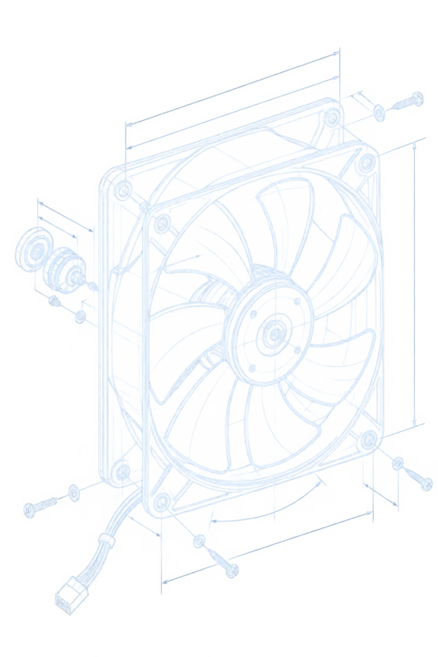
The figure below shows the two paths side by side. On the left, the whole unit comes out and a new unit goes in. On the right, the housing stays, one failed module comes out, and the repaired unit goes back with its airflow restored. The air path is the same in both cases — the difference is what you throw away.

Which part failed? Diagnose before you order
Order nothing until the failed part is named. A part number without a diagnosis is how the wrong module arrives, the shutdown stretches, and the team concludes — wrongly — that part-level repair does not work. Work through the symptoms in the table, run the test in the third column, and write the reading down.
Two measurements anchor every diagnosis: the duty point (airflow and static pressure at the installed condition) and the baseline (the same readings when the fan was healthy). Without a baseline, "hot" and "noisy" are opinions. With one, they are evidence. If no baseline exists, record today's readings anyway — they become the baseline for the next failure.
| Symptom | Likely failed part | Test that names it | Part-level repair realistic? |
|---|---|---|---|
| Grinding or whining noise rising with speed | Bearing | Vibration and temperature at the bearing seat, compared with baseline | Yes, if a bearing cartridge or motor module is sold separately |
| Fan dead, supply present, no fault code | Controller or power stage | Supply voltage at the connector, fault LED or code, insulation resistance | Yes, if the controller module is a separate part |
| Fan runs but at the wrong speed, or hunts | Speed sensor or control signal | PWM duty against measured RPM; 0–10 V input against the RPM curve | Yes for the sensor; check the signal source first |
| Intermittent stops at high temperature | Thermal protection, or a blocked air path | Inlet temperature, filter and coil pressure drop, duty against rating | Often yes — clear the path before ordering parts |
| Impeller cracked, fouled, or unbalanced | Impeller | Visual inspection, vibration spectrum, balance check | Depends — some makers sell the impeller alone, others do not |
| Motor winding shorted or open | Motor | Winding resistance, insulation resistance to frame | Usually a motor-module swap, not a rewind, at small frame sizes |
Match the duty point, not the frame size
The replacement — module or whole unit — must deliver the required airflow at the installed static pressure. That pair of numbers is the duty point, and it is the only honest basis for selection. Catalogue free-air airflow says what the fan does with nothing attached; your cabinet, filter, coil, grille, and duct say what it must do installed. A replacement chosen on frame size or free-air figures alone can bolt in perfectly and still starve the load.
Measure the duty before ordering. Record total airflow by duct traverse or calibrated grille readings with dampers in their normal running state, and total static pressure with a manometer across the unit and then across each section in turn. Repeat both runs: if the two runs disagree by more than ±5%, find out why before you trust either one. The section-by-section pressure budget tells you where the resistance actually sits — and whether a dirty filter, not the fan, is the real problem.
Check the operating point on the P-Q curve, not on the nameplate. Then correct for density if the site is hot or high: a fan is a constant-volume machine, so it moves the same volume at any air density, but the mass flow — and therefore the cooling — falls as density falls. At altitude or high ambient temperature, the volumetric flow has to rise to carry the same heat, and the motor, the bearings, and the electrical clearances become the real limits.
Replacement fans also have to meet current ecodesign requirements. The ErP 2026 changeover tightens what can be sold as a replacement, and the maker's declaration for the exact replacement part belongs in the fan file, not in a brochure. Elektror's ErP 2026 changeover flyer explains what changes and what to check on a replacement. EC makers have responded with ErP 2026-ready ranges — SUNON's Green EC fans for AI infrastructure are one published example — but a maker's ErP claim is only as good as the declaration for the part you actually buy.
Repair, replace, or upgrade: compare on the same numbers
Once the failed part is named and the duty point is measured, the three options can be compared honestly — but only on the same basis. The table below is a framework, not a price list: fill in your own numbers for parts, labour, and downtime, because a generic price would be fiction. What matters is that all three options carry the same rows, so the cheapest part cannot hide an expensive second shutdown.
The energy row deserves care. A repaired fan restores the original efficiency; a whole-unit replacement restores it too. Only an upgrade — a higher-efficiency unit or added speed control — changes the energy bill, and the saving must be calculated at the measured duty, not at free air. The fan laws give the shape: at 80% speed, fan power falls to about 51% of full-speed power, which is why speed control, not just a new fan, is where the large savings live. Third-party project figures report around 30–50% part-load saving from EC speed control (DOE range, attributed) — your room's figure comes from the meter at the duty, not from any vendor's brochure.
Payback is then simple arithmetic: the cost difference between options divided by the measured energy saving per year at the duty. If the repair needs a second shutdown within a year, add that shutdown to the repair's cost. If the upgrade needs new controls or cabling, add that too. The option with the lowest honest total — not the lowest part price — wins.
| Cost item | Repair (part-level) | Whole-unit replacement | Upgrade (higher-efficiency unit) |
|---|---|---|---|
| Parts | One module | Full unit | Full unit plus controls work |
| Labour | Module swap and recommissioning | Full swap and recommissioning | Full swap plus controls integration |
| Downtime window | Shortest, if the module is in stock | One full swap window | Longest, if controls or cabling change |
| Energy after the fix | Restored to original | Restored to original | Lower, if the new unit is more efficient at the measured duty |
| Spares position after | One spare module can cover the fleet | A whole spare unit per type | A new spares family to stock |
| Main risk | Wrong module if the diagnosis was weak | Interface mismatch with existing controls | Controls-integration problems |
Controls and interfaces: the second failure waiting to happen
A replacement fan that bolts in perfectly can still fail on its first run if its control interface does not match the system. EC fans take their speed command in different ways — PWM duty, 0–10 V analogue, or a bus signal — and they report back differently too: tachometer pulses, FG or RD alarm outputs, or nothing at all. A PWM fan wired to a 0–10 V controller, or a fan whose alarm output the controller cannot read, will run at the wrong speed, hunt, or report healthy while the load overheats.
Check the whole control chain before ordering, not just the fan: the controller output type and range, the cable and connector pinout, the fan's input type and range, the supply voltage and its tolerance, and the feedback signal the controller expects. Record each one in the fan file. Then, on the sample, prove the chain end to end: command 25%, 50%, 75%, and 100%, and record the measured RPM at each step. A straight, repeatable command-to-speed line is a pass; a step that saturates, stalls, or hunts is a stop.
Watch the supply as well. A replacement module with a narrower voltage tolerance than the original can trip on the same mains dips the old unit rode through. Ask the maker for the input voltage range, the protection behaviour on brownout, and the restart behaviour after a trip — and test the brownout case on the sample if the site is known for dips.
Spare parts: ask before you buy
The difference between a repairable fan and a disposable one is usually decided at purchase, not at failure. Before you commit to any fan — replacement or new — ask the supplier five questions, and write the answers into the fan file: is the impeller sold separately; is the motor module sold separately; is the controller board sold separately; what is the lead time and minimum order for each; and is there a documented supersession path if a module is revised?
The answers change the spares strategy completely. If modules are sold separately, one spare module can cover a fleet of identical fans, and the next failure becomes a same-day swap. If only whole units are sold, the spare is a whole unit per type, and the fleet's spares bill grows with every variant. For a small team, that distinction is often worth more than a small efficiency difference.
The industry is moving toward modularity: ABB and NOVENCO's modular fan package for data-centre cooling is one published example of fans designed as swappable modules rather than monoliths. Modularity is not a guarantee — a "modular" package still needs the module you need to be sold separately — but it is the right question to ask, and the answer belongs in writing before the purchase order, not after the failure.
Prove it on a sample first
Never release a replacement — module or whole unit — into service without a sample test. The sample is where the diagnosis, the duty match, the interface check, and the spares answers are all proven together, on the real hardware, before the shutdown window. A sample that fails on the bench costs a parcel; a replacement that fails in service costs a shutdown.
Agree the acceptance limits with the supplier before ordering, and write them down. A workable starting set, to be confirmed against the application: airflow within ±5% of the duty requirement at the measured static pressure; input power within +10% of the quoted value at the duty; noise within +3 dB(A) of the quoted value at the duty; and temperature rise within the agreed limit after a full load cycle. Then run the sample in two stages: first on the bench at the duty point, then installed in the real cabinet at real load, with the same four measurements repeated.
The installed test is the one that matters. Bench results prove the fan; installed results prove the system — the filter, the grille, the cable run, and the control chain included. If the installed numbers miss the agreed limits, stop: either the diagnosis was wrong, the duty was mismeasured, or the interface does not match. Each of those has a different fix, and the sample test is what tells you which one.
Keep a fan file: the record that makes the next failure cheap
Every fan in the plant should have a file, and the file should be updated at every failure, repair, and replacement. The file is what turns the next failure from a project back into a part order: the engineer on call opens it, sees the duty, the diagnosis, the part numbers, and the supplier's spares answers, and orders the right module without a site visit.
A usable fan file holds: the measured duty point (airflow and static pressure, with dates and the two-run repeatability); the section-by-section pressure budget; the control chain (command type, feedback type, connector, voltage tolerance); the part numbers of each module and whether each is sold separately, with lead times; the supplier's ErP declaration for the exact part; the sample test results and the agreed acceptance limits; and the failure history, one line per event, with the diagnosis and the fix.
For a small team, the fan file is also the spares policy. When three fans share a module, one spare module covers all three — but only if someone wrote down that they share it. Without the file, every failure starts from zero, and the plant keeps buying whole units for want of a part number.
- Duty point and pressure budget, measured, dated, and repeatable within ±5%
- Control chain: command type, feedback type, connector, and voltage tolerance
- Module part numbers, separate-sale status, lead times, and supersession path
- ErP declaration for the exact replacement part, not a family brochure
- Sample test results against agreed limits, bench and installed
- One line per failure: date, diagnosis, fix, and what the file learned
Where MEGA Tech fits — and where it does not
MEGA Tech is a custom cooling-fan manufacturer. What we do, in the terms our customers use: custom cooling-fan development and manufacturing, fan selection, airflow-path review, sample validation, and batch production. What we do not do is just as important: we do not supply coils, liquid loops, controllers, cabinet safety design, or emergency ventilation, and we do not sell whole fan-wall cabinets or RDHx units as our own supply.
One boundary matters for this guide. MEGA Tech's current published dataset covers DC axial fan variants. EC fans are discussed here as an industry concept, with figures attributed to third parties and original makers — never as MEGA specifications, and never with invented MEGA EC model numbers, L10, or MTBF values. Where a replacement need is a DC axial fan, we select by operating condition, not by part number, and we validate samples on the customer's unit before batch production.
What we need from you to select and validate a replacement: the airflow and static pressure at the installed airflow, the temperature and altitude basis, the voltage tolerance, the control interface, the connector, the envelope, the noise target, and the life assumption. Send those with the fan file, and the selection starts from the duty point — not from a catalogue page. That is the same discipline this guide teaches, applied to our own work.
Engineer FAQ
Q: My EC fan stopped. How do I tell whether it is the bearing, the controller, or the motor? A: Work the symptoms in order: noise rising with speed points to the bearing — check vibration and temperature at the seat against baseline. A dead fan with supply present points to the controller or power stage — check the fault code and insulation resistance. Wrong or hunting speed points to the sensor or the control signal — check PWM duty or 0–10 V against measured RPM. A winding fault is confirmed by resistance and insulation tests, and usually means a motor-module swap at small frame sizes.
Q: Can I replace just the impeller on any EC fan? A: Only if the maker sells the impeller separately and documents balance and compatibility. Some makers do, some do not — ask before you buy, and get the answer in writing. An impeller fitted without balance documentation is a vibration failure waiting for a date.
Q: Is a same-size replacement automatically equivalent? A: No. Equivalence is airflow at the installed static pressure, with a matching control interface and an ErP declaration for the exact part. Same outline dimensions say nothing about the duty point, and free-air catalogue figures say nothing about the installed system.
Q: Do I need to re-validate after a part-level repair? A: Yes. Repeat the duty measurements — airflow, input power, noise, and temperature — and compare them with the pre-failure baseline against the agreed limits. A repair that is not measured is not proven, and the fan file should carry the new baseline.
Q: What does ErP 2026 change for a replacement fan? A: Replacement fans must meet the current ecodesign requirements, and the declaration for the exact part belongs in the fan file. Elektror's ErP 2026 changeover flyer explains what changes and what to check before ordering a replacement.
Q: When is a whole-unit upgrade smarter than a like-for-like repair? A: When the duty has changed, the unit is obsolete with no separate spares, or a higher-efficiency unit pays back on measured energy at the duty. Run all three options through the same cost table — the upgrade wins only on honest totals, not on brochure savings.
Questions for a Design Review
Bring these answers, with measured values attached, before a repair or replacement is released. To ask MEGA Tech for a selection or a sample, send the fan size, voltage, airflow and static-pressure target, quantity, and constraints — plus the fan file if one exists — to inquiry@cnmegatech.com or on WhatsApp, and the selection starts from the duty point.
- Which module failed, and what measurement names it — not just the symptom?
- What is the measured duty point, and do two runs agree within ±5%?
- Does the replacement match the control chain — command, feedback, connector, voltage tolerance?
- Are the failed module and its spares sold separately, with lead times in writing?
- What are the agreed sample acceptance limits, and did the installed test meet them?
- Is the fan file updated, so the next failure starts from a part number, not from zero?