The cabinet that cooks itself
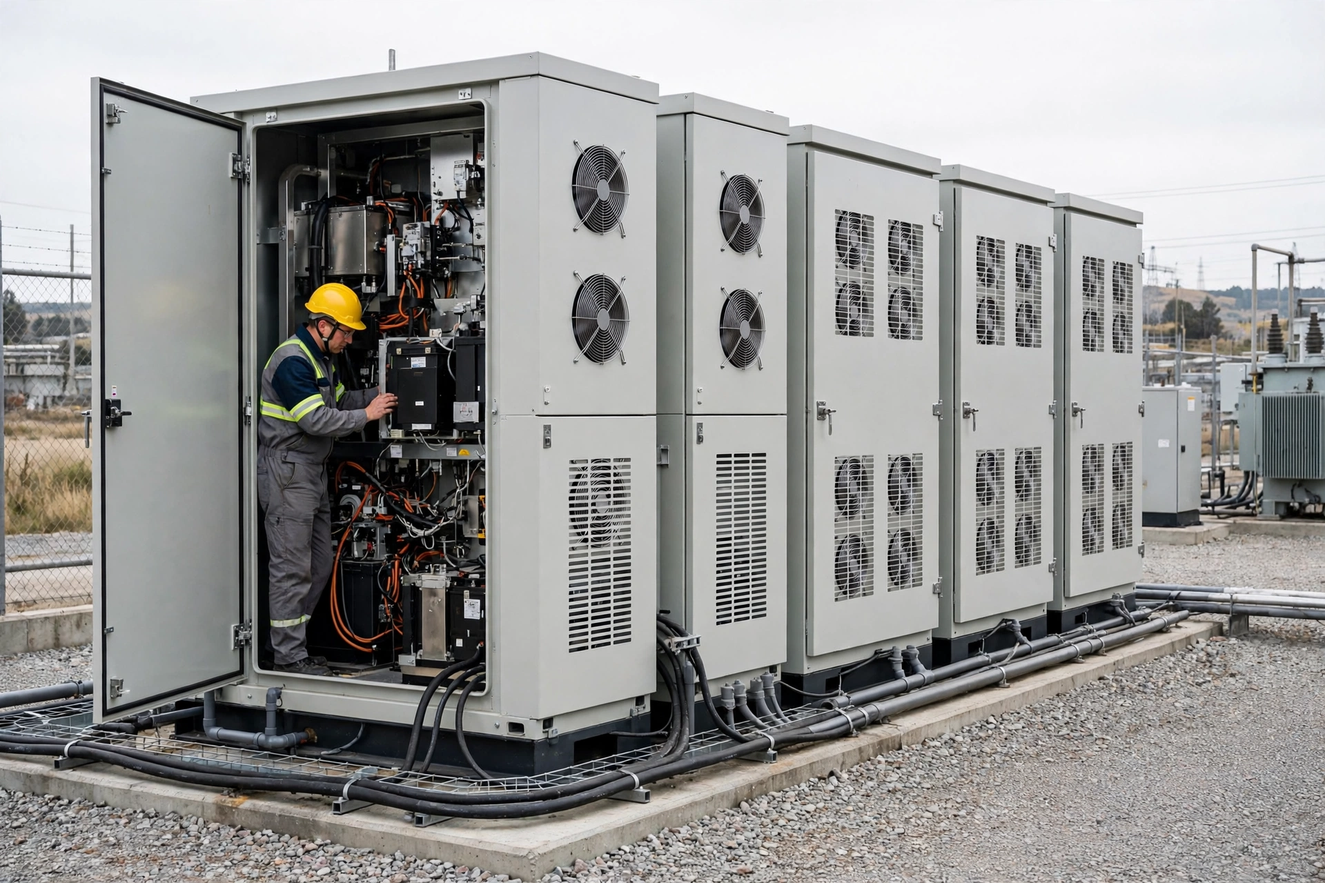
A small commercial battery cabinet does not fail loudly. It cooks quietly: one rack runs hotter than the rest, the fan runs flat out, the filter clogs, and the first sign of trouble is a derated afternoon or a warranty argument.
The heat comes from three places: the cells under charge and discharge, the power conversion system (PCS) turning DC into AC and back, and the battery management system (BMS) with its contactors. In an outdoor cabinet the only exit for that heat is the air path — there is no chilled water loop to hide behind.
That is why air cooling is the default for small commercial and industrial (C&I) storage: it is simpler, cheaper to buy, and easier to maintain than liquid cooling. Liquid only earns its complexity when the system gets large, the charge rate gets high, or the site gets hot.
What goes wrong in practice is almost always a selection error, not bad luck: the top rack runs hottest because nobody measured it, bypass air skips the racks through unsealed gaps, the filter loads up and the fan has no margin left, or one fan fails and nobody notices until the cabinet derates. Every one of those is decided at selection time.
Air or liquid: decide on numbers, not labels
The fork is simple. Air wins when the system is small, the charge rate is low, the climate is mild, and the budget is tight. Liquid wins when the system is large, the power density is high, or the site is hot. An air-cooling vs liquid-cooling comparison for BESS puts the reference numbers side by side: liquid removes roughly twice the heat of air in the reference unit, but costs about 50% more up front and about 70% more to maintain each year, while air uses only fans and draws 2–5% auxiliary power against 5–8% for pumps and controls.
The decision test is whether the air numbers close. If the heat load, the site ambient, and the cell uniformity target all close with air, air is the answer — and the cheaper, simpler one. If they do not close, no fan choice fixes it: change the cooling architecture instead of forcing air onto a liquid problem. For existing sites, the same logic favours air-side retrofits first: containment, EC fan retrofits with dynamic controls, and filter optimization are among the retrofits that pay for themselves in legacy facilities without replacing chillers or air handlers.
ErP 2026 is pushing the same direction on the fan side: makers are launching ErP 2026-compliant EC fans for chillers, dry coolers, and air-handling units, so an air-cooled cabinet designed today can use a current, compliant fan rather than a legacy AC unit.
| Factor | Air cooling | Liquid cooling |
|---|---|---|
| Temperature uniformity | Moderate — airflow patterns set the spread | Excellent — cold plates hold cells close |
| Heat removal capacity (reference unit) | About 70 kW | About 150 kW |
| Auxiliary power, typical | 2–5% of system power | 5–8% of system power |
| Initial cost index (reference) | 100 | 150 |
| Annual maintenance index (reference) | 70 | 120 |
| Best fit | Small, low-rate, mild-climate systems | Large, high-power, hot-climate systems |
Four numbers that size the fan
First, the heat load at the design duty. Get it from the integrator as a number at full-rate charge and discharge — cells plus PCS plus BMS. If only electrical ratings are available, convert with the efficiency the maker states. Never guess the heat load: every later number inherits the error.
Second, the airflow from the heat load and the temperature rise you allow. The relation is Q = P / (ρ · cp · ΔT), with air density ρ = 1.2 kg/m³ and specific heat cp = 1005 J/(kg·K) at ordinary conditions. For 5 kW of heat and a 10 K rise: Q = 5000 / (1.2 × 1005 × 10) = 0.415 m³/s, about 1490 m³/h. That is the airflow the fan must deliver installed, not in free air.
Third, the static pressure budget: intake grille, filter, battery racks, PCS bay, exhaust grille, and duct, added section by section. Size the fan at loaded-filter pressure, not clean-filter pressure, and hold 15–20% margin above the loaded total. A fan sized on clean-filter pressure runs out of margin exactly when the site gets dusty.
Fourth, the noise limit and the dust load, set before the fan is chosen. Fix the noise limit at the site boundary or the nearest window first, then work back to the fan. Fix the filter class and the change interval from the site dust — roadside, construction, and desert sites do not share an interval.
Finally, check the duty point on the P-Q curve at the design temperature, not on the nameplate. A fan is a constant-volume machine: it moves the same volume at any air density, but the mass flow — and therefore the cooling — falls as density falls. At a hot or high site, the volumetric flow has to rise to carry the same heat.
The air path inside the cabinet
The path is low intake, filter, battery racks from bottom to top, PCS bay, high exhaust. Each element adds pressure drop and heat, in that order — which is why the top rack sees the warmest air and why the exhaust must not sit next to the intake on the same face.
Three classic defects show up on every failed cabinet. Bypass: air skips the racks through unsealed gaps and cable cutouts, so the fan moves air without cooling cells — seal the gaps and prove it with a smoke or ribbon check. Stratification: the top rack runs hottest because heat rises and the air has already picked up heat — measure the top and the bottom rack, not just the average. Recirculation: exhaust air re-enters the intake when both grilles share a face or sit in a wind shadow — separate the faces or duct the exhaust clear.
Then the one-fan-out case. If the design has two fans, prove on the sample that the remaining fan holds the duty point when one stops. If it has one fan, say so in the spec and alarm it — an unalarmed single fan is a silent derate waiting to happen.

Temperature rise and cell uniformity: the two limits
Two limits govern the design, and both need numbers before the fan is ordered. The first is the air temperature rise: an 8–12 K rise from intake to exhaust is a workable design window for a small cabinet. Verify it at full-rate charge and discharge at the hottest site ambient, not at a mild test-bench ambient.
The second is the cell-to-cell spread. A spread limit of 5 K is a common acceptance figure integrators write into specs — agree yours in writing before the sample is built. It is a contract number, not a law of physics, and the sample test must measure the coldest and the hottest cell, not the average.
Hot ambient shrinks what air can carry. At 40 °C, air carries about 6% less heat per cubic metre than at 20 °C, because the density is lower. Size on the mass flow at the site temperature, or add the margin explicitly — a fan sized at 20 °C conditions and installed at a 40 °C site is undersized on arrival.
Measure all of it on the sample: intake and exhaust air temperatures, coldest and hottest cell temperatures, at full-rate charge and at full-rate discharge. If the spread or the rise fails at full rate, the fan is not the only suspect — check bypass and recirculation before ordering a bigger fan.
Repeat the key measurements at commissioning and again in the hottest week of the year. A cabinet that passes in spring can fail in August, and a commissioning report that only shows spring numbers will not warn anyone. The seasonal recheck costs one site visit and settles whether the design margin was real or just mild weather.
Noise and dust: the two constraints that shrink the fan
Noise climbs fast with speed, so a small speed cut buys a large noise cut — and a fan forced to run flat out for a clogged filter is loud for a reason you can fix. Where the budget allows, a diffuser or flow grid at the same duty point is worth checking: Delta's ErP 2026-compliant EC fans at Chillventa 2026 report diffusers improving efficiency by about 8–10% and reducing noise by 2–3 dBA at the same operating point, with selected models holding total harmonic current distortion below 5%.
Night mode deserves its own check. A speed cap that satisfies the night noise limit must still hold the duty point — if the capped fan cannot hold the temperature rise, the night cap is not a noise solution, it is a derate schedule. Write the capped duty into the spec and test it.
Dust is the slow version of the same problem. Size the pressure budget at loaded-filter values, and set the filter change interval by pressure drop, not by calendar alone. A cabinet beside a road or a building site loads a filter many times faster than one in a clean yard, and the interval in the manual will not know that.
Controls: speed, staging, and failure alarms
Control the fan by temperature, not by a fixed speed and not by on/off cycling. A PWM or 0–10 V speed command from the cabinet controller, staged against measured temperatures, keeps the cabinet inside its limits across the whole load range and keeps the noise down at part load. On/off-only control thermal-cycles the cells and wears the fan for no benefit.
Where the design claims N+1, prove it. Stage the fans by temperature so the duty is shared, then stop one fan on the sample and confirm the remaining fan holds the duty point, the temperature rise, and the cell spread. An N+1 claim that was never tested with one fan stopped is a label, not a redundancy.
Alarm what you cannot see. Tachometer or FG speed feedback tells the controller the fan is actually turning; an RD locked-rotor alarm catches a seized fan before the cabinet overheats; a filter-clog signal — a differential-pressure switch or a speed-rise detection — catches the slow failure; a high-temperature alarm with a fan-boost action buys time when the ambient spikes.
Log speed in RPM, duty, and alarms together. The log is what settles the argument when a cabinet derates: it shows whether the fan ran, at what speed, against what temperature, and which alarm fired first.
Tie the fan alarms into the cabinet controller and the site monitoring in the same step. An alarm that only lights a local LED is not a monitoring strategy: the site operator needs the alarm, the fan speed, and the cabinet temperature on the same screen, with the same timestamps, so the sequence of a failure can be read after the fact.
Worked example: a 215 kWh C&I cabinet
Take a 215 kWh lithium iron phosphate cabinet with a 100 kW PCS, as an example with stated assumptions. Assume a design heat load of 6 kW at full-rate operation, a site maximum of 40 °C, and a 10 K air temperature rise budget.
Airflow from the heat load: Q = 6000 / (1.2 × 1005 × 10) = 0.498 m³/s, about 1790 m³/h (about 1050 CFM). That is the installed airflow the fan must deliver — before any margin.
The pressure budget below adds every section at clean and at loaded-filter values. The fan duty is the loaded total plus margin: 230 Pa × 1.15 = 265 Pa. So the fan duty point is about 1790 m³/h at 265 Pa.
Fan power at that duty, at an assumed 55% fan total efficiency, is about 0.24 kW — under 0.3% of the 100 kW PCS rating, comfortably inside the 2–5% auxiliary band for air cooling. If the fan power came out near or above that band, the air path — not the fan catalogue — would be the first suspect.
The remaining checks close the example: noise at 1 m against the site limit, one-fan-out duty if the design has two fans, and a loaded-filter retest that repeats the airflow and temperature measurements. Any one of those failing sends the design back, not the fan order forward.
| Path element | Clean ΔP (Pa) | Loaded ΔP (Pa) |
|---|---|---|
| Intake grille | 15 | 20 |
| Filter | 40 | 90 |
| Battery rack | 60 | 60 |
| PCS bay | 30 | 30 |
| Exhaust grille and duct | 25 | 30 |
| Total | 170 | 230 |
Prove it on a sample first
Order a sample and run it against written limits, not against impressions. The sample tests are: duty airflow and static pressure at the design temperature; air temperature rise at full-rate charge and discharge; coldest and hottest cell temperatures; noise at 1 m against the site limit; the same airflow and temperature measurements repeated with a loaded filter; and the one-fan-out test with the alarm check — pull one fan connector and confirm the alarm fires and the remaining fan holds the duty.
Write every limit before the test runs. A test without a pre-written limit is a demonstration, not a validation: it can only pass. When a test fails, fix the air path first — seals, filter area, grille separation — and only then consider a bigger fan. A bigger fan on a bypassed cabinet just moves more air past the cells.
Keep the sample report in the fan file: duty point, temperature rise, cell spread, noise, filter condition, control settings, and alarm log. The next cabinet of the same type starts from that report instead of from zero.
Where MEGA Tech fits — and where it does not
MEGA Tech is a custom cooling-fan manufacturer. What we do, in the terms our customers use: custom cooling-fan development and manufacturing, fan selection, air-path review, sample validation, and batch production. Our published range is DC axial fans, selected by operating condition — airflow and static pressure at the installed point — not by part number, with samples validated on the customer's unit before batch orders.
What we do not do matters just as much. We do not supply liquid loops, coils, cabinet safety design, emergency ventilation, or whole cabinets. If your numbers say liquid cooling, we say so too: a fan supplier that forces air onto a liquid problem is selling you a failure, and a cabinet that needs a liquid loop will not be saved by a bigger fan.
Our manufacturing holds ISO 9001, CE, and RoHS. Every article on this site carries the same boundary: third-party figures are attributed to their makers, and MEGA Tech figures only ever describe MEGA Tech products that are actually published.
To ask MEGA Tech for a selection or a sample, send the fan size, voltage, airflow and static-pressure target, quantity, and constraints — plus the operating conditions the fan must survive. The selection starts from the duty point, and the sample proves it before any batch is discussed.
Engineer FAQ
Q: Can air cooling handle a 215 kWh cabinet in a hot climate? A: It depends on the heat load, the site maximum ambient, and the temperature rise budget — run the numbers at the site temperature, not at test-bench conditions. If the airflow, the pressure budget, and the cell spread all close with margin, air works. If they do not close, change the cooling architecture instead of forcing a bigger fan.
Q: How do I know the fan will hold up with a loaded filter? A: Size the fan at loaded-filter pressure, repeat the airflow and temperature measurements with a loaded filter on the sample, and set the change interval by pressure drop. A filter changed on a calendar instead of a pressure reading will always be changed too late or too early.
Q: One fan fails — does the cabinet overheat? A: Only if the one-fan-out duty was never checked. Stop one fan on the sample and confirm the remaining fan holds the duty point, the temperature rise, and the cell spread. If it does not, the design is not redundant whatever the datasheet claims.
Q: Is a bigger fan always quieter? A: Not always. A bigger fan at lower speed is usually quieter at the same duty, but only if the installed point is clean — inlet distortion, a tight grille, or a blocked filter can make a bigger fan louder than a smaller one running free. Check noise at the installed point, not on the catalogue page.
Q: What do you need from me to select a fan? A: Airflow and static pressure at that airflow, the temperature basis, voltage tolerance, control interface, connector, envelope, noise target, and life assumption. With those eight inputs the selection starts from the duty point; without them it starts from a guess.
Questions for a Design Review
Bring these answers, with measured values attached, before a fan selection is released. To ask MEGA Tech for a selection or a sample, send the fan size, voltage, airflow and static-pressure target, quantity, and constraints — plus the operating conditions — to inquiry@cnmegatech.com or on WhatsApp, and the selection starts from the duty point.
- What is the design heat load at full rate, and who measured it — not just the nameplate?
- What airflow and static pressure does the loaded-filter budget demand, and where is the margin?
- What are the air temperature rise and the cell-to-cell spread limits, agreed in writing?
- Does the remaining fan hold the duty point when one fan stops, and did the alarm fire?
- What is the noise limit at the site boundary, and does the capped night speed still hold the duty?
- What are the agreed sample acceptance limits, and did the installed test meet all of them?