A European Home-Energy Integrator Had a Quiet-Hours Problem
The residential solar-storage system passed a daytime thermal check, but the owner noticed a repeating fan ramp late in the evening when the house was quiet.
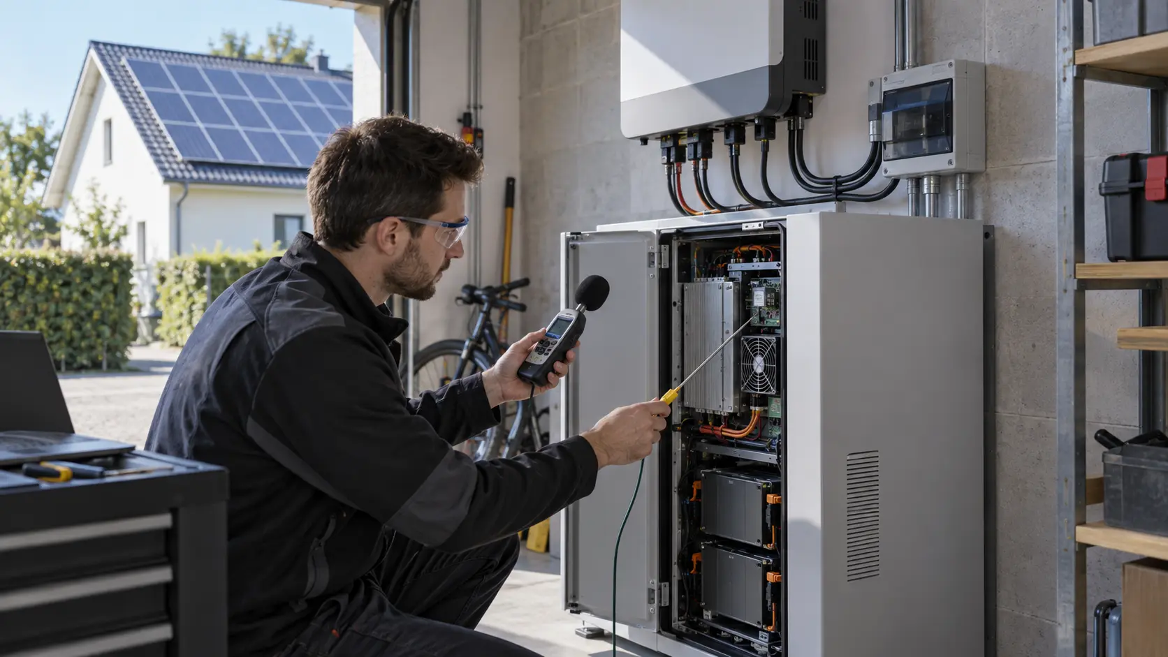
The anonymized customer was integrating a wall-mounted battery with a hybrid inverter for European homes. The battery chemistry, protection logic and complete product approval remained the customer's responsibility. The cooling question concerned the air-cooled inverter and auxiliary electronics inside a compact outdoor-rated enclosure, not every residential battery on the market.
At midday, solar production and battery charging pushed the inverter power stage hard enough to create a local hotspot near the upper electronics bay. At night, the thermal load fell, but a simple temperature switch still drove the fan between off and a relatively high command. The result was a product that was thermally acceptable in the lab but acoustically irritating near a garage, utility room or bedroom wall.
The customer asked MEGA Tech for a small sample program rather than a catalogue substitution. The fan had to fit the existing cut-out, move useful air through the heat source, start reliably at low voltage, provide feedback to the controller and keep the low-load sound signature unobtrusive.
Not Every Residential ESS Needs a Fan
A credible cooling decision starts by separating the battery thermal architecture from the inverter enclosure problem.
European home-energy products use different approaches: some rely on passive conduction and enclosure clearances, some use liquid or refrigerant-based thermal management, and some air-cooled inverter sections use fans only when power electronics need forced convection. A fan should not be added simply because a battery has a large kWh rating.
Public installation documentation also shows why the installed environment matters. Tesla's Powerwall 3 documentation specifies a -20°C to 50°C operating range, notes possible power derating above 40°C and requires clearance around the unit to preserve airflow. Those are system-level requirements, not a license to copy a fan from another product. The exact cooling architecture, airflow openings and control logic remain product-specific.
For this case, the design boundary was explicit: the customer owned the battery safety assessment and complete system certification; MEGA Tech worked on the replaceable or customized fan path serving the inverter and electronics bay. That boundary keeps the article useful without suggesting that one fan solves cell balancing, thermal runaway protection or the complete ESS approval path.
Start With Heat Load, Not Battery Capacity
A 10 kWh label does not tell an engineer how much heat the fan must remove at a particular moment.
The customer split the duty into solar peak, battery charge, battery discharge, backup operation and idle communication. The important inputs were inverter efficiency at each power level, heat-sink temperature, inlet air temperature, enclosure leakage, allowable component temperature and the time spent at each state.
As a screening example, assume the air-cooled electronics release 180 W and the designer permits a 12 K average air rise. Using an air-side heat-capacity estimate of 1.2 kJ/(m³·K), the ideal flow is Q = 180/(1,200 x 12) = 0.0125 m³/s, or about 26.5 CFM. If the same loss must be handled at an 8 K rise, the estimate becomes 0.0188 m³/s, or about 39.8 CFM. These are planning estimates, not customer test results; heat spreading, recirculation, altitude and component-to-air resistance still have to be measured.
The useful selection target was therefore an installed operating point with pressure margin. A fan rated at 40 CFM in free air may deliver much less behind a grille, narrow duct, filter or heat sink. The team recorded differential pressure and local temperature at the actual path before deciding whether more RPM, a different impeller, a blower or a mechanical redesign was justified.
| Input | Why it matters | Evidence to collect |
|---|---|---|
| Power-stage loss | Sets the heat that must leave the inverter bay | Efficiency map or measured electrical loss by duty |
| Outdoor ambient | Changes thermal headroom and fan life | Worst-case site temperature and sun exposure |
| Air-path resistance | Moves the fan operating point | Grille, filter, heat sink and duct pressure drop |
| Occupied-room proximity | Turns tonal noise into a product issue | Sound pressure and spectrum at realistic distance |
| Control behavior | Determines night cycling and standby energy | PWM command, minimum start, FG and alarm behavior |
The First Sample Exposed a Recirculation and Control Problem
The original fan was not necessarily too small; the enclosure was asking it to solve two different problems with one crude command.
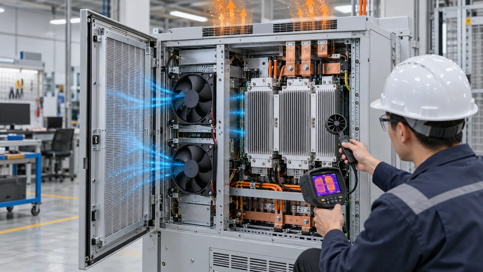
With the first sample installed, the fan spun and the average enclosure temperature looked acceptable. A smoke or particle visualization showed that part of the discharge returned toward the inlet because the hot exhaust pocket had no defined exit path. The upper inverter heat sink received less fresh air than the fan's free-air rating implied.
The second issue was the control threshold. When the system was near its thermal threshold, the controller jumped from a quiet state to a high speed. That jump created a tonal event that was more noticeable than a steady broadband sound at the same average thermal duty. At night, the fan could cycle because the sensor was seeing a local hot layer rather than the actual power-stage temperature.
MEGA Tech proposed three changes for the next sample: guide the discharge across the heat sink, separate inlet and exhaust clearance, and replace the two-state command with a measured PWM curve. The intent was not to hide a thermal problem by slowing the fan; it was to keep the component temperature within the agreed limit while avoiding unnecessary speed changes.

Sample 02: Select the Fan for the Installed Pressure and Night Noise
The candidate comparison included axial and compact blower options, because the enclosure path contained a turn and a restrictive outlet.
A short, open path can favor an axial fan, while a narrow duct or heat-sink channel may benefit from a centrifugal blower. The decision was made from a pressure-flow test with the real grille and duct, not from the maximum CFM line in a catalogue. The customer also checked whether the fan could maintain its operating point as the filter or inlet surface became partially loaded.
The acoustic target was not reduced to one headline dB value. The team listened for blade-pass or commutation tones, measured sound pressure at a realistic wall or room position and compared the spectrum during ramp-up, steady operation and stop-start cycling. A lower overall level can still sound worse if a narrow tonal peak appears near the living space.
The selection also covered the low-command region. A practical fan sample needs a defined minimum start command, stable low speed, FG feedback that remains interpretable at that speed and a predictable response when the controller drops voltage during standby. The customer could then choose a quiet night curve without gambling on intermittent stall or delayed restart.
Sample 03: Validate High Ambient, Solar Peak and Standby Together
The final test matrix combined the conditions that are often tested separately in a residential product.
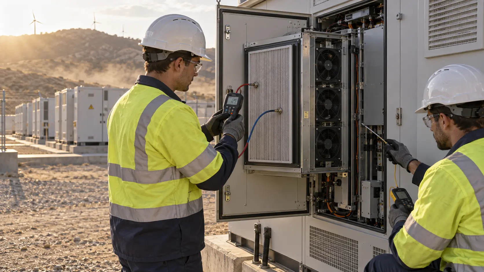
The customer repeated four states: high solar input with charging, evening discharge, low-load standby and a high-ambient enclosure condition. Thermocouples were placed on the inverter heat sink, the hottest power-stage region, inlet air and exhaust air. The test also logged PWM, RPM, current, differential pressure and fault feedback.
A useful sanity check was the fan's own energy. If a 3 W fan runs for eight hours during a summer day, the fan consumes about 24 Wh before controller losses. That is small compared with household energy, but repeated night cycling can create an audible nuisance and a measurable standby cost. The figure is an engineering estimate, not a claim about this customer's final product.
The customer then repeated the test with a partially restricted inlet to represent dust or maintenance delay. The acceptance decision was based on component temperature and control stability at the loaded operating point. A clean-air pass alone was not accepted because an outdoor residential cabinet sees insects, dust, pollen, moisture and installation variability.
Result: A Quieter Residential ESS Sample With More Honest Thermal Evidence
The customer received a tuned sample and a test plan that could be repeated by the product team before production release.
The revised sample kept the heat source in the intended airflow path, reduced unnecessary high-speed transitions and made the controller's low-speed behavior visible through feedback. The project did not claim that one fan architecture is correct for every European home battery; it established a repeatable method for air-cooled inverter cabinets that must operate near people.
The transferable lesson is that residential storage changes the priority order. A commercial cabinet may tolerate a fan that is clearly audible if it protects a power stage. A home product must also consider night-time acoustics, wall transmission, visual integration, maintenance access and the difference between a quiet but unstable low-speed point and a genuinely controlled one.
For a production decision, the customer still needs to complete its own electrical, fire, battery, EMC, ingress and system-level safety approvals. MEGA Tech's contribution is the custom fan, interface and installed cooling evidence that makes those reviews less dependent on catalogue assumptions.
How MEGA Tech Supports Residential Solar-Storage Cooling
We help inverter and energy-storage teams move from a cabinet constraint to a testable fan sample.
MEGA Tech can review custom DC axial fans and compact centrifugal blowers for hybrid inverters, AC-coupled storage, DC-coupled cabinets, charger electronics and auxiliary power modules. Depending on the path, the review can cover frame and thickness, pressure-flow behavior, PWM, FG/RD, connector and cable exit, bearing option, temperature range, ingress strategy, noise target and small-batch samples.
For a first review, send the enclosure section or physical sample, heat load by operating state, ambient range, inlet and exhaust locations, pressure estimate, fan envelope, voltage tolerance, control interface, sound target, service condition and expected quantity. We can help compare a catalogue-size replacement with a modified sample and then validate it in the customer's installed path.
We do not present an anonymized case as a certification or a guarantee for a complete residential energy product. The value is the engineering workflow: define the source, measure the path, tune the fan and control response, then repeat the test at the real operating point.
Engineer Questions About This Residential ESS Case
These questions help thermal, mechanical and procurement teams avoid a misleading fan swap.
Q: Do all home batteries need a cooling fan? A: No. The battery and inverter architecture must be identified first; some systems are passive or liquid-cooled, while an air-cooled inverter bay may still need forced convection.
Q: Why not select the highest-CFM fan? A: Free-air flow does not include grille, heat sink, duct, filter or enclosure resistance. The installed P-Q operating point is the useful number.
Q: Why is night noise part of thermal design? A: A home system may be installed close to occupied rooms. A tonal peak or repeated ramp can be unacceptable even when the average dB value looks reasonable.
Q: What should be measured besides temperature? A: PWM, RPM or FG, current, differential pressure, inlet and exhaust temperature, hotspot temperature, acoustic spectrum and the condition of the filter or grille.
Q: Can MEGA Tech match a European inverter fan? A: We can review the original fan and installed conditions, then propose a custom or replacement sample. Performance must be verified on the customer's cabinet rather than inferred from frame size alone.
Residential ESS Fan Design-Review Checklist
Use this checklist before freezing the fan, grille and controller in a European home-energy product.
- Is the fan cooling the battery, the inverter power stage, or only auxiliary electronics?
- What are the worst solar, charge, discharge, backup and night-standby states?
- Where is the real heat source, and can hot exhaust recirculate to the inlet?
- What pressure does the grille, heat sink, filter and duct create at the target flow?
- What is the minimum stable PWM command and the guaranteed restart condition?
- Is FG or RD available, and what does the system do after a fan fault?
- Has the acoustic spectrum been measured at the actual wall or room position?
- Has partial inlet loading, high ambient, dust and service access been included?
- Which fan, duct, controller or enclosure changes require a new installed sample test?