After you pick air cooling, the rack fans decide whether the cells stay balanced
Across the air-versus-liquid debate, one gap the datasheets never close is what actually happens inside the rack once you commit to air. The battery's worst enemy is not raw heat — it is uneven heat. Airflow that races through the gap between the cell casing and the module frame and slips around the pack instead of through it leaves the far cells nearly uncooled, and that hotspot is where a system-year of degradation quietly starts.
A grid-scale energy-storage project may be designed for a long service life, so the cooling system has to preserve temperature uniformity over the actual duty cycle, filter condition and maintenance plan. Air-cooled and liquid-cooled designs can show very different temperature spreads, but there is no universal ± value: cell format, spacing, heat generation, coolant path and control strategy decide the result. The gap matters because uneven temperature can accelerate local aging, increase imbalance and force the battery-management system to limit the rack to the weakest condition.
The safety margin narrows the same way. Thermal runaway is a cell and system safety event, not a temperature number that a fan supplier can define by itself. The design team must evaluate the hottest measured location, propagation behaviour, detection, isolation and emergency response within the applicable BESS safety process. Uniformity is therefore both a capacity concern and one input to the safety case.
A published container study gives a useful scale reference without creating a universal target: its optimized air-cooling layout reported an average battery temperature of 38.37°C, a temperature gradient of 4.77°C and a pressure loss of 12.08 Pa. Those values belong to that study's geometry, heat load and boundary conditions; they are a reminder to report temperature spread and pressure together, not a pass/fail limit for every rack.
UL 9540A should also be kept in the correct lane. It evaluates thermal-runaway propagation, heat and gas release, fire and deflagration behaviour at defined test levels; it does not certify a fan's airflow, bearing life or the thermal uniformity of an arbitrary rack. Cooling validation and BESS safety testing must be coordinated, not substituted for one another.
This article is about the difference between a fan that spins and a fan that actually delivers balanced airflow through a dense rack: the airflow-bypass problem, the static-pressure floor every cell path needs, the layout levers that peer-reviewed CFD work has quantified, and the redundancy and sensing that stop a small fan failure from becoming a thermal incident.
The real problem is airflow bypass, not airflow volume
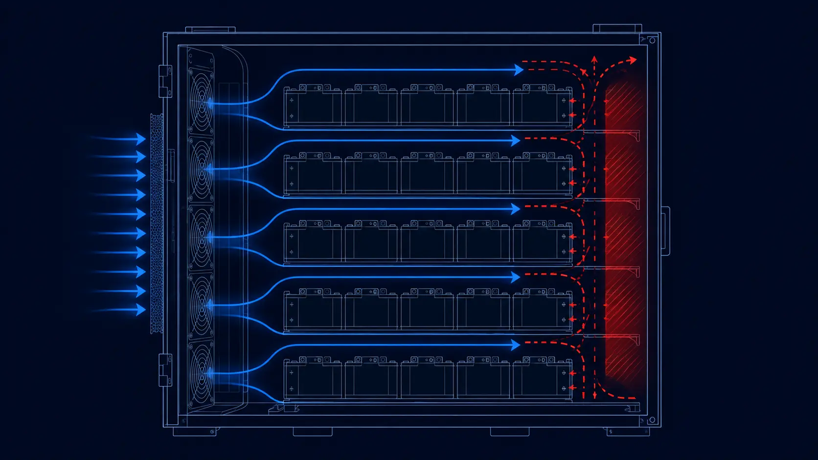
Add more flow and you do not automatically get more uniform temperatures. Air follows the path of least resistance, and in a densely packed battery rack the easiest path is the slot between the cell casing and the module frame and around the pack edges. That channel shorts the intended through-pack path, so the cells down-wind of it settle in a dead zone even while the fan runs at full speed and the tachometer reports healthy.
Thermal and CFD studies of storage cabinets repeatedly examine the same failure modes: unequal airflow distribution between battery gaps, bypass around the intended path and recirculation of already-warmed air. The size of the temperature penalty is design-specific, but the mechanism is stable. Both defects steal cooling from exactly the cells that need it most.
And the rack can drift into bypass over time even if it was built well. Intake filters load with dust, gaskets relax and replacement modules can have slightly different frames; each change alters the intended and bypass resistance. This is why the bypass problem is a lifetime-sizing and maintenance problem, not a commissioning snapshot.
The useful lesson from published layout studies is not one universal temperature improvement. It is that changing inlet/outlet layout, plenums, baffles and cell spacing can materially improve uniformity at the same heat load, but every improvement must be rechecked for pressure drop, fan power, manufacturability and service access.
The takeaway is not 'use a bigger fan'. It is: make the fan overcome the gap-bypass path so air has no comfortable shortcut. That is a static-pressure job, and it changes which fan you can actually use.
Flow uniformity, not flow volume, is the variable that decides how balanced a rack runs. A published BESS study that reorganised the cooling layout along the same lines used in data-centre aisles reported the maximum cell-to-cell temperature difference falling from 31.2 C to 3.5 C and the average battery temperature from 30.5 C to 24.7 C at an unchanged heat load, with the coefficient of performance improving roughly fourfold. The authors attribute the gain to airflow uniformity and to a longer air residence time inside the pack rather than to more air. That is precisely the mechanism a bypass path destroys: air that short-circuits over the modules never spends time on a cell surface, so it removes heat from nothing at all.

The layout levers CFD work has already quantified
Before anyone buys a different fan, the rack's own geometry offers the first levers. Compare serial and parallel ventilation, fresh-air access to each row, inlet and outlet placement, plenum shape, baffles and cell spacing in a thermal or CFD model. Published studies report material improvements from these changes, but their exact temperature and pressure results belong to the tested geometry, not to every BESS rack.
Duct shape is the second lever. Tapered inlet and outlet plenums, opposite-wall exhausts and secondary vents can improve distribution and reduce recirculation, while baffle plates and deflectors guide air into starved channels. The trade-off is pressure drop, fan power, noise and serviceability; every layout change must be evaluated against the fan's system curve.
Cell spacing works from the other direction. Narrower gaps can raise channel velocity, but they also increase pressure drop and may complicate assembly, thermal expansion and service. The correct spacing is a system trade: velocity and pressure are bought with impedance, and the whole design has to be balanced rather than optimized cell-by-cell.
The pattern across all of it: layout first, fan second. But every lever that closes a bypass or adds a deflector also stiffens the system's resistance curve — so the fan selection must be made against the improved rack, not the naive one.
Published container work puts numbers on those levers. In a 2.5 MWh air-cooled station, optimising the louver-fin supply to a 90-degree supply angle with an 18 mm cell spacing cut the average battery temperature rise by 18% and the temperature difference by 23% - before any change to the fan. That is the size of the prize available from geometry alone, and it is why the layout review belongs ahead of the fan shortlist.
The static-pressure floor: why a standard axial fan stalls against a rack
This is the number that separates fans that work in battery cabinets from fans that only spin. A dense rack loading — intake filter, module enclosures, tightly spaced cells, busbars and exhaust grille — can create substantial system impedance. The actual pressure drop must be measured or calculated for the rack. A standard axial fan optimized for free-air duty may lose most of its useful airflow when faced with that resistance, so the fan must be selected from the intersection of its static-pressure curve and the rack system curve.
'More airflow' is therefore meaningless on its own; what matters is airflow at the rack's actual resistance. A high-static-pressure axial fan is built with blade geometry and a stronger motor precisely so its pressure–airflow curve stays high enough to keep useful airflow when the pack resists it. That is what lets the cells down-wind of the first row get cooled instead of starved.
Sealing is the quiet partner of pressure. Duct-joint leakage and module-bay gaps re-create the bypass path you just engineered away — supplier guidance for air-cooled BESS treats gasketed joints and leak inspection as airflow-design work, not just weatherproofing, because every leak is a shortcut that re-routes pressurized air around the cells.
So the choice is not free-air CFM versus pressure — it is whether, at the loaded rack's measured resistance, the fan still holds enough airflow across every cell row.
The counter-example matters just as much. In the same study, raising the supply volume flow rate tenfold on the unoptimised layout increased the temperature difference by 28%. More air through an unbalanced path does not flatten the field; it amplifies whichever channels were already favoured. So the number worth specifying is the pressure required to make every cell row part of the preferred path, not the total CFM printed on the nameplate.
| Model | Size / 24V | Free-air CFM | Static pressure | Noise |
|---|---|---|---|---|
| MG12038HV24X | 120×120×38 mm | ~210 CFM | ~29 mmH2O | ~65 dBA |
| MG8038HV24X | 80×80×38 mm | ~129 CFM | ~127 mmH2O | ~79 dBA |
| MG6038VH24X | 60×60×38 mm | ~66 CFM | ~178 mmH2O | ~68 dBA |
Fewer but larger fans, run slower, is the reliability play
Inside a rack the engineer's instinct is usually more small fans. A smaller fan may need higher speed to push pressure, which can increase acoustic output and bearing duty; and every fan is another monitored component and service point. The trade-off must be evaluated against the rack's cooling map and required redundancy.
One candidate approach is to use fewer, larger, high-static fans positioned to create a more uniform pressure field across the pack, then PWM-control them so they run at the lowest validated speed that meets cell-temperature limits. This is not automatically more reliable: fan spacing, single-fault temperature rise, service access and spare strategy still need to be tested. The parasitic-power result depends on fan count, speed, pressure drop and control policy, so measure it at representative load points instead of assuming a universal watt range.
Parasitic power deserves its own line item because it compounds. Auxiliary consumption in a storage plant runs around the clock, every day of the year; shaving even a few tens of watts per rack at part load is a measurable share of the round-trip-efficiency story that project financiers audit. The fan curve you choose at design time is a lifetime energy-purchase decision, not a component spec.
Noise follows the same geometry. Racks sited near substations, commercial rooftops or residential boundaries inherit local noise limits, and a fleet of small fans at high RPM can create more acoustic risk than fewer fans at a validated moderate speed. Duct treatment and speed scheduling help, but the installed rack must be measured at the duty points that matter.
Because each is a mover, treating fans as a field-replaceable, maintainable unit — with service access and no blocked-filter surprise — matters as much as the fan spec itself. A filter you cannot reach to change erases the very thermal margin the fan was sized to create.
Redundancy, sensing and layout — the parts that stop a fan fault becoming an incident
The fan is a small component carrying an outsized responsibility: in an air-cooled rack it helps maintain the intended thermal operating window, but it is not a substitute for BESS thermal-runaway detection, isolation, fire protection or emergency-ventilation design. A cooling design that works on paper has to survive a real fan failure, which is a system question as much as a component one.
The checklist engineers converge on for battery-rack fan systems looks like this: N+1 redundancy — if the worst-case thermal load needs three fans, fit four, so a single failure never leaves the rack under-cooled. A model-appropriate FG/tacho or alarm output so the controller sees a stalled or dead fan, plus a temperature diagnostic, rather than trusting RPM alone — because a fan can spin normally while airflow is choked. And layout validated with CFD before metal is cut, so dead zones are fixed in the model, not found at commissioning.
The response to a confirmed fan fault deserves design attention too, because the safe answer is not always 'keep running'. The rack and BMS team should define whether to derate, isolate or pause on confirmed cooling loss, based on the battery chemistry, thermal model, operating state and applicable safety requirements. That control logic belongs in the system safety case, not as an afterthought to the fan specification.
Add temperature-sensed fan throttling on top: multi-point cell thermistors feeding a PID-based PWM ramp that matches airflow to real demand — full authority at peak, near-idle at night, which is exactly how parasitic power and bearing wear stay low across years of service. The sensor set matters as much as the fans: a rack that measures airflow or inlet-to-outlet temperature rise can see bypass returning as filters load, while one that only reads RPM cannot.
- Design for N+1: four fans where worst-case calls for three, so one loss never leaves the rack under-cooled.
- Fit an FG/tacho or alarm output and a temperature diagnostic — never trust RPM to prove airflow.
- Confirm filter and fan service access; a filter you can’t clean erases your thermal margin.
- Run PID/PWM throttling from multi-point cell thermistors to cut parasitic power and bearing wear at part load.
- Validate airflow with CFD before fabrication — fix dead zones in the model, not at commissioning.
Select the fan at the loaded-rack working point, and specify what you need
Across the whole cabinet the discipline is the same as in any restricted path: the fan delivers its free-air CFM only with nothing in the way. Once the intake filter, the module rows and the exhaust grille are installed, the airflow the cells actually feel is the fan's output at the loaded impedance — and that is the only number worth sizing on.
The catalogue range covers this deliberately, from a compact high-static blower for a tight local heat source through a mid-size high-static axial for the module to a larger-volume axial for whole-rack flow. Specify explicitly your loaded-filter pressure drop, your target airflow at that point, the required fan life under the project duty cycle, and which outputs (PWM, FG, alarm) the controller expects — because a fan specified to the rack's real curve is more likely to preserve the designed thermal margin over service life.
Develop the fan and rack airflow as one system
An air-cooled battery rack needs more than a high-pressure catalogue fan. It needs a fan matched to the actual enclosure, filter, module spacing and service conditions.
MEGA Tech can work with BESS teams from the first airflow requirement. We review the rack layout, cell or module arrangement, heat load, target temperature spread, filter and gasket resistance, ambient range, voltage, noise, control method and expected duty cycle, then define the fan working point that the rack actually needs.
If the standard fan platform is close but the product needs a different combination of airflow, pressure, size, speed or control, we can develop a customized sample around the rack: frame and thickness, bearing selection, PWM, FG/RD feedback, connector, cable length, mounting details and environmental protection. The sample is tested with the real or representative filter, duct and module path so bypass and dead zones are measured rather than guessed.
This sample-first process gives new storage-equipment companies room to refine the rack before volume production. Once the airflow field, temperature uniformity, noise and reliability are confirmed, the approved fan specification can move into consistent, cost-conscious production and long-term service planning.
- Measure the loaded-rack working point and identify bypass paths.
- Customize pressure, size, bearing, control and wiring details around the rack.
- Test temperature uniformity, airflow, pressure, noise and failure response.
- Transfer the approved sample into reliable production for the full product program.
Engineer FAQ: BESS Rack Airflow Bypass and Static Pressure
Air-cooled battery racks need a measured thermal and airflow safety case; a fan nameplate cannot prove cell uniformity or incident prevention.
Q: Why can a BESS rack have enough total airflow but still develop hot cells? A: Air can bypass cell rows through gaps, leaks or low-resistance channels. Measure the spatial airflow and temperature field across representative modules instead of using total CFM or one room sensor as proof.
Q: Is there a universal battery temperature spread that every rack must meet? A: No. The acceptable spread depends on cell chemistry, module design, heat load, operating state, controls and the applicable product and installation requirements. Set it with the battery and system safety teams.
Q: How should the BESS fan be selected? A: Build or measure the rack system curve, including filters, module gaps, baffles, seals and exhaust restrictions. Select the fan at the required airflow and loaded resistance, then check density, noise, power, control range and service conditions.
Q: Can N+1 fans replace thermal-runaway protection? A: No. Redundancy can preserve cooling after a defined fan fault, but it does not replace cell monitoring, detection, isolation, fire protection or the applicable BESS safety analysis and testing.
Q: What should a customized fan sample prove? A: Test the populated rack or representative module path with the real filter, seals, baffles and controls. Record airflow distribution, cell or module temperatures, fan voltage, speed, current, noise, fault response, clean and loaded conditions, and the planned service access.
Q: Why can adding airflow make the temperature spread worse? A: Because flow divides by resistance, not by intent. Raising total flow through a rack that has an open bypass and unequal module gaps amplifies the imbalance that already exists - the favoured channels simply take a larger share of the increase. Published container work reports the temperature difference widening by 28% when supply flow was raised tenfold on an unoptimised layout. Balance the geometry first, then raise flow.
- Tie every numerical answer to voltage, speed, temperature, mounting and test condition.
- Separate catalogue maximums, engineering estimates and measured application results.
- Use the FAQ to define the next measurement or sample-validation step.
Checklist — what an air-cooled battery rack needs from its fans
Working through a rack fan system that keeps cells balanced for a decade:
- Beat the bypass: choose high-static-pressure fans whose P–Q curve holds the required airflow at the measured loaded-rack pressure.
- Fix the layout first: compare parallel and serial flow, inlet and outlet placement, tapered plenums, secondary vents and sealed joints — then size the fan against the improved rack.
- Treat flow uniformity - not total CFM - as the acceptance criterion, and expect the spread to widen if flow is raised before the layout is balanced.
- Size at the loaded working point, not free-air — state the target CFM at your loaded-filter pressure drop.
- Prefer fewer, larger fans run at moderate speed with PWM; add N+1 so no single failure leaves the rack under-cooled.
- Watch airflow with FG/advisory signals and temperature, not RPM alone; confirm service access for filters and fans.
- Validate the airflow field with CFD before build, then specify bearing life and outputs for the project duty cycle and service plan.