A European BESS Integrator Found the Problem After Commissioning
The cabinet passed its clean-filter test, then lost thermal margin when summer heat and dust loading arrived together.
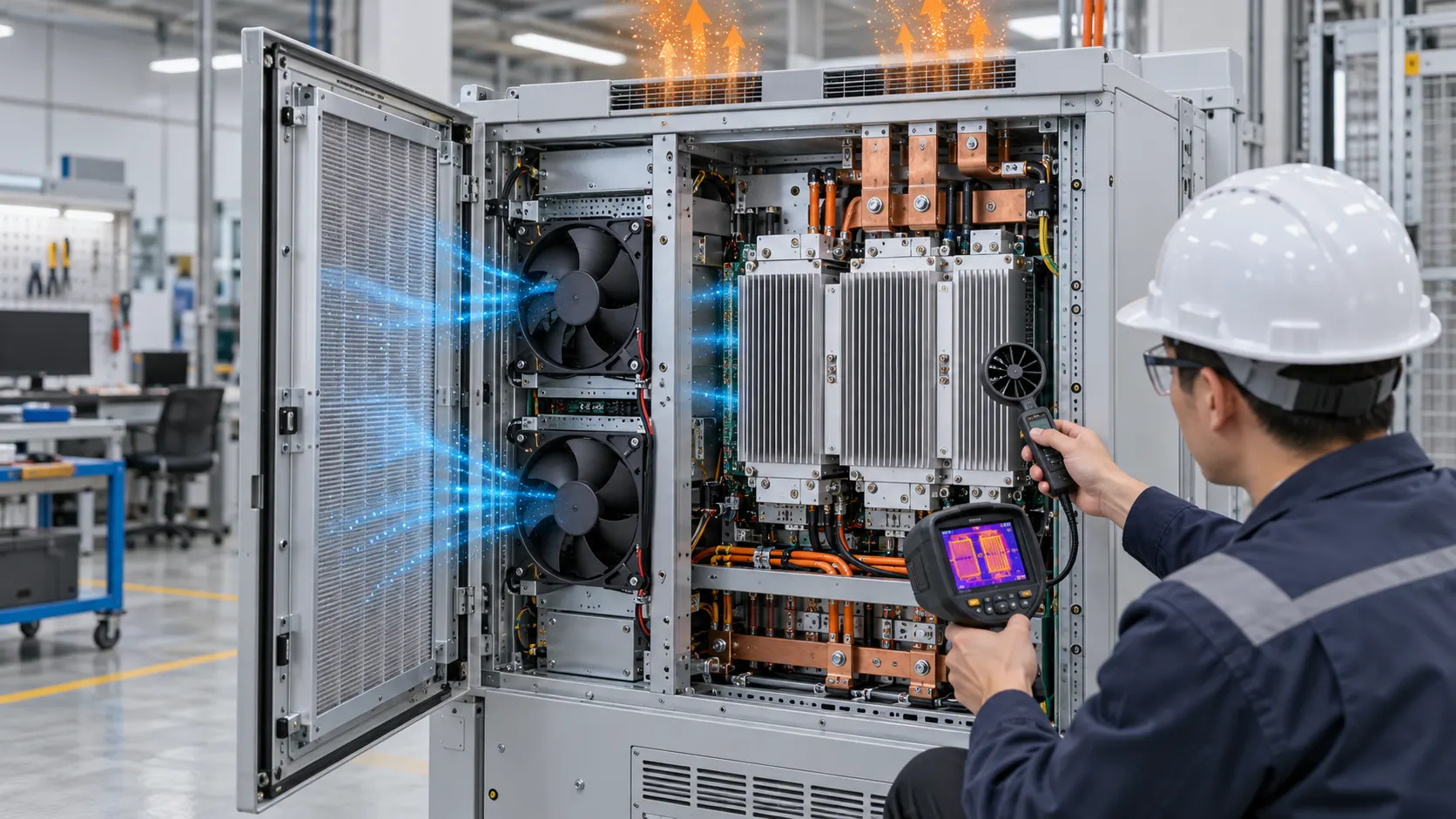
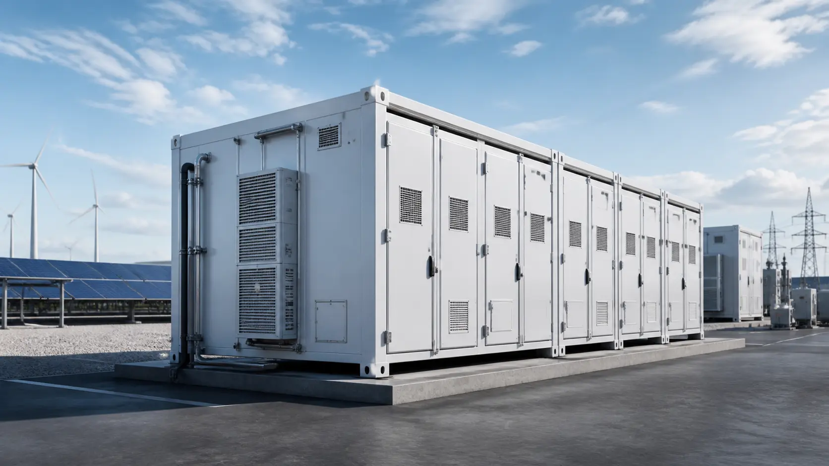
An anonymized European energy-storage integrator was preparing an outdoor air-cooled cabinet for a dry, dusty industrial site. The enclosure used filtered intake air and compact DC fans to move air through the power electronics and battery-module compartments. The first commissioning check passed with a new filter, but the field symptom appeared later: the controller commanded more speed, the fan FG signal still looked normal, and the temperature spread across the cabinet became larger during a high-load period.
The customer initially described it as a fan-life problem. The evidence suggested a different question: had the installed air path moved beyond the fan's useful pressure margin? MEGA Tech reviewed the cabinet drawing, filter curve, grille, module arrangement, voltage range and controller interface. Customer identity and released project values remain confidential; this case explains the engineering method and the type of sample validation used.
Why the Clean-Cabinet Test Was Not Enough
A new filter defines the starting point; it does not prove end-of-service airflow.
The fan does not see a catalogue condition. It sees the sum of filter, intake grille, louvre, heat sink, module channels, wiring obstructions and exhaust losses. As the filter loads, the system curve rises. The operating point moves toward lower airflow unless the fan has enough pressure head and the controller has enough speed margin. A normal FG signal only says that the rotor is turning at the expected speed; it does not prove that the same amount of air is passing through the battery modules.
This distinction is consistent with practical filter-maintenance guidance: resistance should be monitored or linked to a defined replacement decision, not treated as an invisible calendar event. DOE maintenance material describes dirty filters as increasing static pressure and reducing airflow, while current BESS engineering guidance likewise recommends recording the installed pressure condition rather than approving a fan from a clean bench result alone. These references guide the method, not a universal BESS alarm limit.
The customer therefore supplied three test states: clean filter, a representative loaded condition approved by the filter supplier, and a high-ambient state at the cabinet's declared operating limit. The team measured inlet temperature, fan command, RPM, current, differential pressure and hotspot temperatures at each state.
| Observation | Possible interpretation | Evidence to collect |
|---|---|---|
| RPM remains near command while temperature rises | Airflow may be falling at higher system resistance | Filter ΔP, total static pressure and airflow |
| PWM rises and current increases | Controller is using headroom to hold duty | PWM, voltage, current and temperature trend |
| Pressure is low but dust is downstream | Filter frame or gasket may bypass | Visual inspection, smoke check and particle path |
| Only one zone runs hot | Distribution or blockage may be uneven | Zone temperatures and branch pressure/airflow |
| Fan is at limit in hot weather | Ambient density and heat load have consumed margin | Ambient temperature, load and fan operating point |
The Working-Point Review Used a Simple Pressure Budget
The team did not start by asking for the largest CFM number. It built the installed resistance budget first.
For a first screening model, the air path was represented as ΔP_system = ΔP_filter + ΔP_grille + ΔP_module + ΔP_outlet. Each term was tied to the stated airflow and test condition. The model remained a planning tool until the complete cabinet was measured. This matters because a filter value at one face velocity cannot be transferred to a different filter area or airflow without checking its curve.
A useful planning example shows the direction of the error. Suppose the clean-filter condition contributes 60 Pa at 0.30 m³/s and the representative loaded condition contributes 150 Pa at the same reference flow. The added 90 Pa is not a small correction if the fan's available pressure margin at 0.30 m³/s is only 110 Pa. The fan may need more speed, or the actual operating point will move left and deliver less air. These numbers are an illustrative calculation, not the customer's released data.
The team also checked the density basis. At a fixed volumetric flow, hotter air carries less mass and removes less heat per unit volume. A fan selection that is acceptable at a mild laboratory inlet temperature can lose thermal margin on a hot site day even before the filter reaches its service limit. The thermal acceptance test therefore used the declared high-ambient condition rather than a comfortable room-temperature shortcut.
Sample 01: Reproduce the Customer's Filter and Cabinet
The first sample review was about test fidelity, not immediately changing the fan.
MEGA Tech asked for the actual filter frame, grille, mounting panel, fan cut-out, module obstruction and cable route. The sample was installed in the same orientation as the cabinet. Pressure taps were placed upstream and downstream of the filter, and a second measurement point was used to understand the pressure seen by the fan. The team recorded the same command and supply voltage used by the cabinet controller.
This step often finds a hidden bypass. A filter that is not sealed can show an unexpectedly low measured pressure drop while dust passes around the media. Conversely, a distorted gasket can add local resistance that is absent from the supplier's flat test fixture. The visible filter color is not a valid service criterion by itself; pressure and thermal response are more defensible.
The result was a baseline matrix with clean-filter pressure, RPM, current, airflow reference and zone temperatures. That matrix became the comparison point for every later change. A fan was not accepted because it sounded or spun well in open air; it had to reproduce the installed duty with the correct mechanical interfaces.

Sample 02: Add Pressure and Temperature Evidence to the Fan Signals
The customer needed a service decision that could be seen by the controller and by the maintenance team.
The revised fan sample used the cabinet's required voltage and a defined PWM command range, with FG feedback and the agreed fault output where the controller supported it. Those signals were logged beside filter differential pressure and zone temperatures. The purpose was not to make the fan compensate forever; it was to identify when the system was approaching the edge of its validated duty.
A practical control sequence can have three layers: normal closed-loop temperature control, a limited temporary speed reserve, and a service or derating decision when pressure or temperature evidence crosses the project threshold. The threshold must come from the filter, cabinet thermal limit and acceptance test. It should not be copied from another enclosure.
As an estimate, a 100 Pa increase in resistance at 0.30 m³/s represents 30 W of ideal air power before fan and motor losses are considered, using P_air = Q × ΔP. At an assumed combined efficiency of 45%, the electrical input needed to overcome that added resistance would be roughly 67 W if the system insisted on holding the same flow. This is an engineering estimate to show why a dirty filter can affect both heat removal and auxiliary power; actual power must be measured on the selected fan.
| Signal | Clean baseline | Loaded/high-ambient decision |
|---|---|---|
| Fan command and RPM | Record stable operating point | Confirm reserve and saturation behavior |
| Fan voltage and current | Record startup and steady state | Check power rise and low-voltage margin |
| Filter differential pressure | Record at named flow/condition | Define project-specific maintenance trigger |
| Zone temperatures | Record hottest point and spread | Confirm thermal limit and derating response |
| FG/RD or fault status | Confirm timing and interpretation | Test missing feedback and recovery |
Sample 03: Validate the Loaded Filter at High Ambient
The meaningful acceptance point is the combination most likely to expose a weak margin.
The high-ambient run combined the representative heat load, the declared hot inlet temperature and the loaded filter state. The cabinet was allowed to reach a repeatable condition before comparing the hottest zone, temperature spread, fan speed, current and pressure. The team also observed whether one branch or one side of the enclosure received easier air while another zone became starved.
This is where a generic recommendation such as 'increase fan RPM' can fail. If the fan is already close to its maximum pressure capability, more command may add noise and power without restoring the missing airflow. If the bypass path is easier than the battery channels, a higher RPM can even strengthen the wrong flow path. The physical installation and the fan curve must be reviewed together.
The customer approved the sample only after the loaded/high-ambient state met its own thermal and control requirements. Exact customer thresholds and final values were not released. The transferable decision was that the fan, filter service point and controller alarm were approved as one package, rather than as three unrelated specifications.
Result: A Maintenance Decision Replaced a Guess
The integrator moved from a clean-filter pass/fail test to a condition-based review that procurement and service could repeat.
The completed validation package documented the clean reference, the representative loaded state, the pressure measurement points, the fan command and feedback behavior, the high-ambient condition, the hottest zone and the response when the fan approached its limit. It also defined what happens next: service the filter, inspect the seal and grille, derate the cabinet or escalate the fault according to the cabinet's approved control plan.
The engineering value was not a promise that one fan eliminates every BESS thermal risk. It was a clearer boundary. MEGA Tech supplied and tuned the fan sample around the air path; the integrator retained responsibility for the battery thermal model, BMS limits, cabinet safety functions and site maintenance procedure. That separation made the quotation more credible because the fan requirement was expressed as an installed duty, not a free-air marketing number.
For a new project, a simple review sheet can prevent a late redesign: heat load by operating mode, inlet temperature range, filter initial and final resistance, grille and module losses, airflow or pressure target, fan voltage, PWM frequency, FG/RD logic, connector, envelope, noise limit, life assumption and maintenance trigger. These are the inputs MEGA Tech needs to build a useful first sample.
How MEGA Tech Supports Custom BESS Cooling Fans
MEGA Tech helps convert a cabinet constraint into a sample that can be tested on the customer's assembly.
We provide custom DC axial fans and compact centrifugal blowers selected by the actual airflow and static-pressure duty, not by a part number or free-air CFM alone. Depending on the path, the design review can cover blade and motor behavior, high-static-pressure performance, PWM response, FG/RD feedback, connector and cable routing, mounting, temperature range and the sample's installed acoustic behavior.
For a first review, send the cabinet section or 3D model, filter curve and frame, grille and louvre details, module or heat-sink obstruction, heat load by mode, inlet temperature and altitude, voltage tolerance, PWM frequency and pinout, connector, fan envelope, noise target, expected life and the intended maintenance state. If the cabinet uses redundancy, include the failed-fan and reverse-flow conditions.
MEGA Tech can start with a small build, adjust the fan-side design around the customer's sample and return a configuration for installed validation. We do not supply the battery cells, liquid loop, BMS, cabinet safety system, fire protection or emergency ventilation design. Those system functions must be reviewed by the responsible battery and enclosure teams.
Engineer Questions About This Case
Use these questions before freezing a BESS fan, filter or maintenance specification.
Q: Can PWM compensate for every dirty filter? A: No. It can use available headroom, but it increases power and acoustic load and eventually reaches a pressure or speed limit. Validate the loaded state.
Q: Does normal FG feedback prove airflow? A: No. FG confirms rotor-speed feedback. Pair it with pressure, airflow reference and hotspot temperatures on the installed cabinet.
Q: Should the filter alarm be based only on a calendar interval? A: A calendar can support service planning, but the trigger should be tied to the approved filter, pressure condition and thermal acceptance evidence.
Q: Why can the measured filter pressure look low while the cabinet is dusty? A: A damaged or poorly sealed frame can bypass the media. Inspect the gasket and dust path instead of interpreting a low ΔP as healthy airflow.
Q: What is the fastest useful fan-selection input? A: Give the airflow target at its static pressure, heat load, inlet temperature, fan envelope, supply and control interface. A free-air CFM number alone is not enough.
Q: Is this a published customer performance guarantee? A: No. The customer is anonymized and released values are confidential. The workflow and planning equations are transferable; the final cabinet must be tested with its own data.
Questions for a BESS Fan Design Review
A compact checklist for engineering, procurement and commissioning teams.
- What is the required airflow at the stated total static pressure, not at free air?
- What are the clean, representative loaded and final filter resistance points?
- Where are the pressure taps, and is the filter frame sealed against bypass?
- What heat load and inlet temperature define the acceptance test?
- What happens when the fan reaches its maximum command or loses FG/RD feedback?
- Does the loaded condition create uneven module airflow or a local hot zone?
- Are voltage tolerance, PWM frequency, startup, fault recovery and connector pinout frozen?
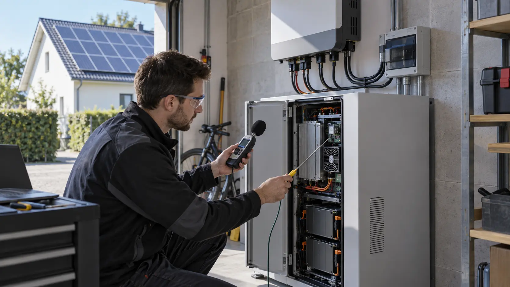
- Is noise measured at the same installed duty as the thermal test?
- Which values belong to the fan supplier, and which require complete cabinet approval?