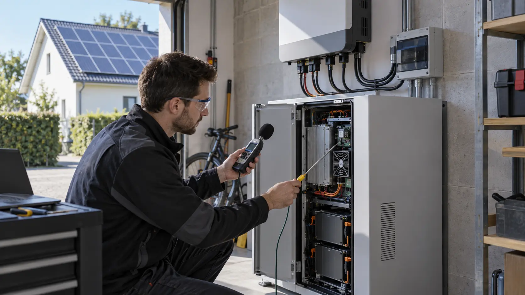
The Cabinet Problem: Inverter Heat Has to Leave Through a Restricted Path
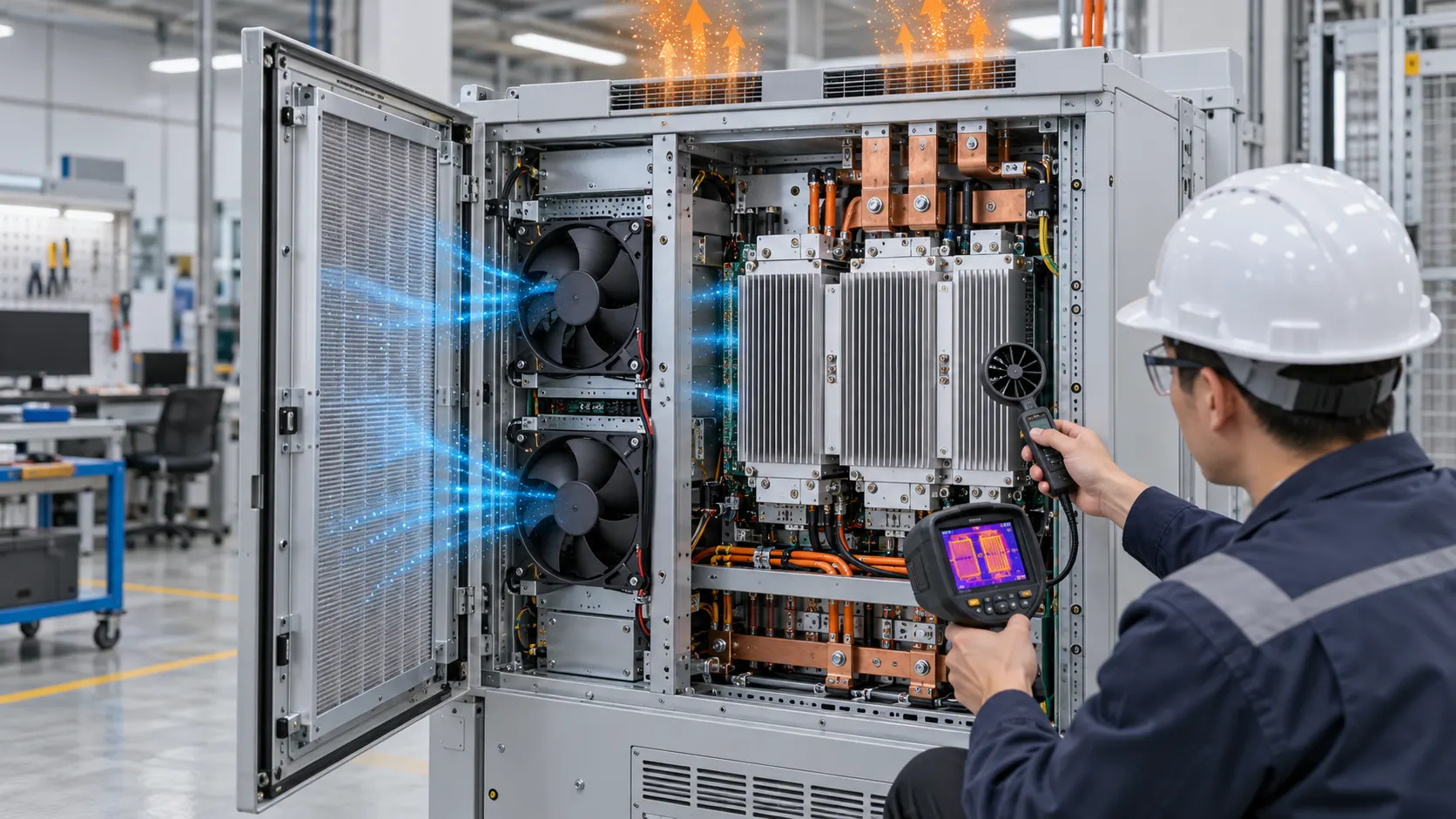
A solar inverter or PCS cabinet can look simple from the outside: an intake, a fan bank, a heatsink and an exhaust. The thermal review is harder because every grille, filter, busbar cover, power module and cable gap changes the air path.
This case pattern describes an anonymised power-electronics project in which the team was considering a replacement fan for a solar inverter and storage PCS cabinet. The original fan fit the envelope, but a clean-filter bench result did not explain the high temperature observed after installation. The cabinet had a removable intake filter, a dense power stage, several heatsinks and a short exhaust path. A replacement could not be approved by frame size, rated voltage or free-air airflow alone.
The first review separated the heat sources. Semiconductor switching losses, magnetics, busbars, control electronics and auxiliary power supplies do not heat the same air volume. The hottest heatsink may be downstream of a restriction, while a fan near the door may move a large volume without washing the critical fins. The team mapped inlet temperature, heatsink temperature, outlet temperature, fan current and pressure at the restriction before comparing candidates.
The project record is an engineering pattern, not a universal performance claim. The final fan, control setting and thermal limits must be selected on the customer's cabinet, at the customer's ambient, altitude, filter state and duty cycle.
Why Clean-Filter Airflow Is Not the Release Condition
A new filter is only one state in the service life of an inverter cabinet. The fan must still deliver the required airflow when the filter, grille and heatsink path are at their agreed design resistance.
A fan's free-air number is measured at approximately zero static pressure. A cabinet never offers zero pressure. The intake guard, filter media, fan guard, heatsink fins, cable bundles, bends and exhaust grille all consume pressure. When dust loads the filter, the system resistance rises and the operating point moves along the fan curve toward lower airflow. The motor may still spin at the commanded speed while the power module receives less cooling air.
The review therefore defined at least three states: clean filter, service-limit filter and a blocked-intake protection check. The service-limit state was the release basis; clean-filter data was retained as a commissioning reference. The team also recorded whether the cabinet was positive-pressure or negative-pressure. A negative-pressure enclosure can pull unfiltered air through cable entries and panel gaps, while positive pressure can increase leakage if the outlet is undersized.
Do not convert an illustrative pressure budget into a product guarantee. For a real approval, measure differential pressure across the filter, the fan assembly and the complete cabinet path. Record the instrument location and whether pressure is gauge, static or total pressure so that supplier data and installed data can be compared honestly.
The Engineering Hook: Fan Curve, Filter Pressure and Hotspot Temperature
The useful question is not how much air the fan moves in free air. It is where the fan curve intersects the cabinet system curve, and whether the resulting airflow protects the hottest component.
A practical test starts with a heat balance. As an illustrative screening example, a cabinet rejecting 1,800 W with an allowed average air rise of 15 K would need approximately Q = 1,800 / (1,200 x 15) = 0.10 m3/s, or about 212 CFM. The 1,200 J/(m3 K) heat-capacity estimate is a screening assumption, not a measured cabinet result. Local heatsink limits, recirculation and non-uniform distribution can require more airflow than the average calculation suggests.
The second screen is the pressure path. Suppose the clean path measures 90 Pa at the provisional flow and the service-limit filter raises that path to 150 Pa. The fan candidate must be checked at 150 Pa, not at its zero-pressure airflow. The numbers here illustrate the method only; the customer's measured filter curve, grille area and cabinet geometry replace them in the release file.
Temperature mapping then closes the loop. Place sensors at the inverter power module, the hottest heatsink base, the cabinet inlet and the exhaust. Compare temperature at the same input power, ambient, fan command and filter state. If airflow increases but the hotspot does not improve, look for bypass, recirculation or a local fin restriction before simply increasing RPM.
Sample Review: 24 V / 48 V Fan Candidates
The site catalogue gives useful starting points, but a catalogue series is a candidate for sample review rather than an approval for a complete PCS cabinet.
For a medium cabinet with a 120 mm opening and a restrictive filter path, the 120 x 120 x 38 mm DC axial family is a logical first candidate. The published catalogue contains 12 V, 24 V and 48 V variants in the B Type family, and a D Type family with higher-pressure variants. The selection should be narrowed by the required airflow at the measured pressure, connector, control method, current limit, noise target and mounting depth.
For a larger opening or a lower number of fan positions, the 172 x 150 x 51 mm DC axial family is another candidate. Its 12 V, 24 V and 48 V variants can be compared when the electrical architecture is fixed. The 48 V option may simplify distribution over a larger cabinet, but voltage alone does not prove compatibility with the inverter's fan driver, protection threshold or fault input.
Use the 120 x 120 x 38 mm DC axial fan candidate and the 172 x 150 x 51 mm DC axial fan candidate as starting points. The fan selection tool can narrow catalogue records, but the customer still needs a sample installed in the real air path. Product pages provide catalogue records; they do not replace a cabinet validation report.
Validation Sequence: Clean, Loaded and High-Ambient States
A replacement fan is credible when the same test sequence covers commissioning, service life and the most difficult ambient condition.
Step one is electrical compatibility. Confirm rated voltage, operating-voltage tolerance, startup current, steady current, PWM frequency and logic level, FG or RD pull-up arrangement, connector pinout and fault interpretation. A fan with the same frame and voltage can still fail if the controller expects a different tachometer pulse count or treats a low-speed signal as a fault.
Step two is mechanical integration. Photograph the installed fan orientation, guard, gasket, cable exit, filter frame and nearby obstructions. Check that the fan does not draw air around the filter or leak around the shroud. Confirm screw depth, vibration isolation and service access. For a replacement, compare the impeller clearance and outlet area, not only the outside dimensions.
Step three is thermal and airflow measurement. Run the clean filter at the defined power profile, then repeat at the service-limit filter and high ambient. Record airflow with a suitable traverse or calibrated flow device, pressure at the agreed taps, fan speed, current, inlet temperature, hotspot temperature, exhaust temperature and sound level. Keep the power profile long enough to reach a repeatable thermal state; a short pass can hide heat soak.
Step four is abnormal-state response. Simulate fan stop, tach loss, PWM loss, blocked intake and sensor disagreement. The inverter maker owns the derating, alarm and shutdown logic. MEGA Tech can provide fan-side response and samples, but cannot approve the complete inverter safety case.
Control and Fault Feedback: PWM, FG/RD and Safe Derating
The fan interface is part of the thermal design. A mechanically correct fan can still be an electrical mismatch if control and feedback are not reviewed together.
PWM control should be checked at the actual duty range used by the inverter. Measure startup at the minimum commanded duty, low-speed stability, response to a step change and behavior after a brownout. Do not assume that a fan reaches a useful operating point merely because the controller reports a high duty command. The installed pressure can make the minimum stable speed higher than a free-air bench suggests.
FG or RD feedback needs an agreed interpretation. Confirm pulses per revolution, pull-up voltage, high and low levels, missing-pulse timeout and the behavior during startup. A fault output may be open collector, a tachometer may be frequency output and the controller may need different filtering for each. Record the fan's actual waveform at the connector, not just the controller's software state.
For a PCS cabinet, a safe derating strategy may be more valuable than a maximum-RPM setting. The controller can combine inlet temperature, heatsink temperature, fan feedback and power level. If the filter pressure rises, the system should raise an alarm or request service before the hotspot crosses its limit. The exact thresholds belong to the inverter design and must be verified by its owner.
Interactive: Watch the Operating Point Move
The animated schematic below is a qualitative model of why a filter-loaded cabinet needs a different release check.
In the first panel, the clean filter has lower resistance and more of the fan's available pressure can be used to move air across the heatsink. In the second, the same commanded fan can encounter a higher system resistance. The particles still show rotation, but useful flow through the thermal path is reduced. This is why a speed or current reading is not a substitute for an installed airflow or pressure measurement.
The third panel shows the engineering action: plot the fan curve and the measured system curve, then check the intersection for each service state. The green and red markers are not measured values. They show the type of comparison that belongs in the validation report. The report should also state density basis, fan voltage, control setting, filter condition and instrument uncertainty.

Validation Result: A Measured Replacement Basis
The useful result of a fan replacement project is a traceable acceptance basis, not a promise that every cabinet with the same opening will behave the same way.
The anonymised review closed with a comparison sheet for the original fan and each candidate. It listed installed airflow at clean and service-limit pressure, fan current, voltage, startup behavior, FG or RD waveform, noise, inlet and hotspot temperatures, filter differential pressure and the response to a simulated fan fault. The candidate that passed was the one that met the customer's thermal and control requirements in the installed path.
The report kept catalogue and project data separate. Catalogue values were cited with the relevant model and test condition. Project results were tagged with instrument, location, ambient, input power and filter state. Illustrative calculations were labelled as screening estimates. This separation prevents a plausible number from being copied into a product claim or a future tender without its boundary conditions.
The same method also made maintenance easier. The integrator could define when to clean or replace the filter, what alarm should appear, how much derating remained and what evidence was required after a fan replacement. Procurement received a real specification: frame and thickness, voltage tolerance, installed airflow and pressure, control, feedback, connector, environment, noise and sample approval.
How MEGA Tech Supports Solar Inverter and PCS Fan Customization
MEGA Tech develops and manufactures custom cooling fans and supports fan-side selection, air-path review, sample validation and volume production around the customer's real equipment.
We can review DC axial fans and compact centrifugal blowers by operating condition rather than part number. The review can include fan frame and thickness, airflow and static pressure at that airflow, filter and grille losses, shroud geometry, flow direction, 12 V / 24 V / 48 V electrical options, PWM, FG or RD feedback, connector, cable exit, vibration mounting, noise target and environmental assumptions. A catalogue candidate is then converted into a sample plan for the customer's cabinet.
Please provide the cabinet drawings or a physical sample, heat load by operating mode, required airflow and static pressure at that airflow, ambient temperature, altitude, voltage tolerance, fan quantity, control interface, connector, noise target, filter condition, life assumption and fault behavior. If the current design is a replacement, send the existing fan model, installation photos, measured temperatures, pressure taps and controller waveform. These inputs allow the sample to be judged at the real duty instead of a free-air headline.
MEGA Tech's boundary is equally important. We are a custom cooling-fan manufacturer. The complete inverter or PCS cabinet, coils, liquid loops, pumps, controllers, BMS, fire protection, emergency ventilation, electrical safety and final system certification remain with the system integrator or equipment manufacturer. We do not supply complete inverter cabinets or liquid-cooling systems. Our role is the fan, fan customization, air-path review, sample validation and production support.
Engineer FAQ
These questions are useful before a solar inverter or PCS fan replacement enters design freeze.
Q: Can I select a replacement by matching 120 mm or 172 mm frame size? A: No. Match the installed airflow and pressure, electrical interface, control, feedback, noise, environment and service state. The same outline can contain very different curves.
Q: Should the fan be selected from clean-filter airflow? A: Use clean-filter data for commissioning, but release against the agreed service-limit filter and high-ambient condition.
Q: Is 48 V automatically better for a large cabinet? A: No. It may fit the distribution architecture, but check controller compatibility, voltage tolerance, startup, current protection and fault input.
Q: Does a higher RPM guarantee lower hotspot temperature? A: No. Bypass, recirculation, a blocked filter or a restrictive heatsink can prevent useful flow from reaching the component.
Q: What should the validation report contain? A: Include fan curve and system curve conditions, airflow, pressure, voltage, current, control, feedback, filter state, ambient, heat load, hotspot temperature, noise and abnormal-state response.
Q: Can MEGA Tech provide a sample recommendation? A: Yes. Send the fan size, voltage, quantity, target airflow and pressure, control interface, noise, environment, drawings and current measurements. We can then review candidate samples.
Questions for a Design Review
Use these questions to keep the fan replacement decision connected to the real PCS cabinet.
What is the hottest component and what temperature limit applies at the worst ambient and power profile? What airflow is required at that component, and how was it measured? Which pressure taps define the installed duty? What are the clean and service-limit filter pressure drops? Does the test include the actual guard, gasket, shroud, cable route and exhaust grille?
Which voltage, PWM, FG or RD interface does the controller actually support? What happens when the fan stalls, loses feedback, starts slowly or sees a brownout? How will the cabinet derate, alarm or shut down? Is the noise target measured at the same operating point as the thermal result?
Before asking for a sample, send the current fan model, fan envelope, cabinet and filter drawings, airflow and pressure target, voltage and control details, quantity, ambient and altitude, noise target, life assumption and measured thermal data. For a review, use the MEGA Tech products catalogue, the fan selection tool and the WhatsApp engineering contact. Include your request for the P-Q curve or a custom specification at inquiry@cnmegatech.com.