Tender requirements beyond airflow
The tender was not asking for a fan with a larger CFM number. It needed a controllable, monitored cooling subsystem that could be integrated into the cabinet control strategy.
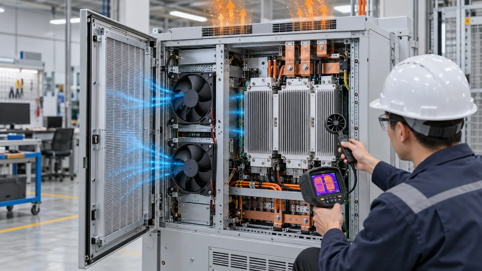
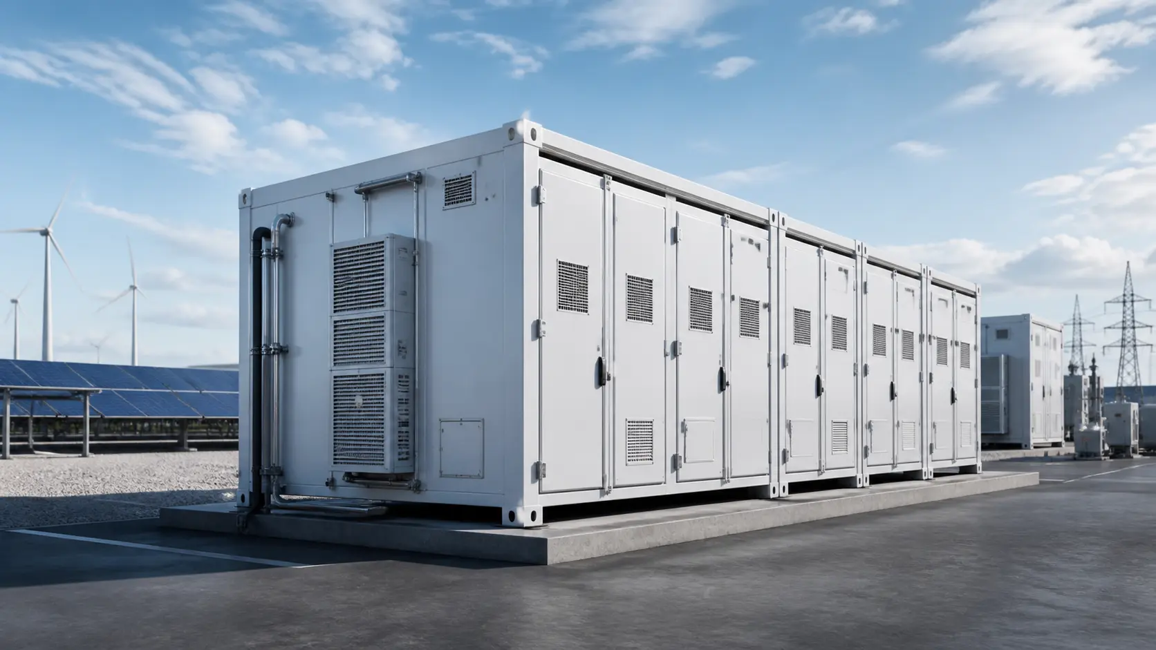
A client preparing a high-spec energy storage cabinet tender needed more than a standard fan. The cooling solution required staged temperature response, a defined fan operating point through the cabinet resistance and a clear fan-stall indication strategy.
The temperature points below were project requirements for the tender, not universal BESS limits. The final thresholds must be set by the battery, cabinet, BMS and applicable installation requirements, with sensor location and measurement uncertainty documented.
- Project requirement below 35 C: standby mode.
- Project requirement at 35 C: 50% speed.
- Project requirement at 40 C: 70% speed.
- At the project maximum limit: 100% speed and stall alert capability.
- Confirm thresholds against the battery and cabinet thermal limits before release.
Control and fault-visibility approach
The useful design question is not only whether the fan can change speed, but whether the cabinet can see, interpret and respond to a cooling fault.
The published project describes a custom 175×69 mm centrifugal fan approach combining multi-stage speed control, stall detection, LED indication and a signal to the host system. The visual indicator was selected because audible alarms can be ineffective in noisy installations.
For the engineering handoff, the fault logic should define what the fan reports, what the cabinet controller does next and what remains powered. A missing tachometer signal, stalled rotor, over-current condition or invalid sensor value should not be treated as the same event without a deliberate response. The cabinet may raise an alarm, switch to a redundant fan, reduce charge/discharge power or enter a protected state depending on the system safety analysis.
- Stall detection in the fan control logic.
- LED indicator for local fault visibility.
- System signal for the cabinet control layer.
- Defined response to lost feedback, blocked airflow and fan power loss.
Integration support
The project included control logic, installation guidance and a power-supply optimisation concept for multiple fans. This support was intended to make the fan system easier to integrate into the cabinet rather than treat it as an isolated component.
The integration review should also include the pressure drop of filters, grilles and battery modules, fan spacing, airflow direction, service access, connector pinout, cable length and the power budget during simultaneous start-up. These details decide whether the staged control works in the installed cabinet or only on an open bench.
- Application: energy storage cabinet.
- Product: 175×69 mm centrifugal fan.
- Focus: control logic, monitoring and installation support.
Validation and safety boundary
A cabinet cooling fan protects the normal operating envelope; it is not a substitute for the BMS, gas detection, suppression or emergency ventilation strategy.
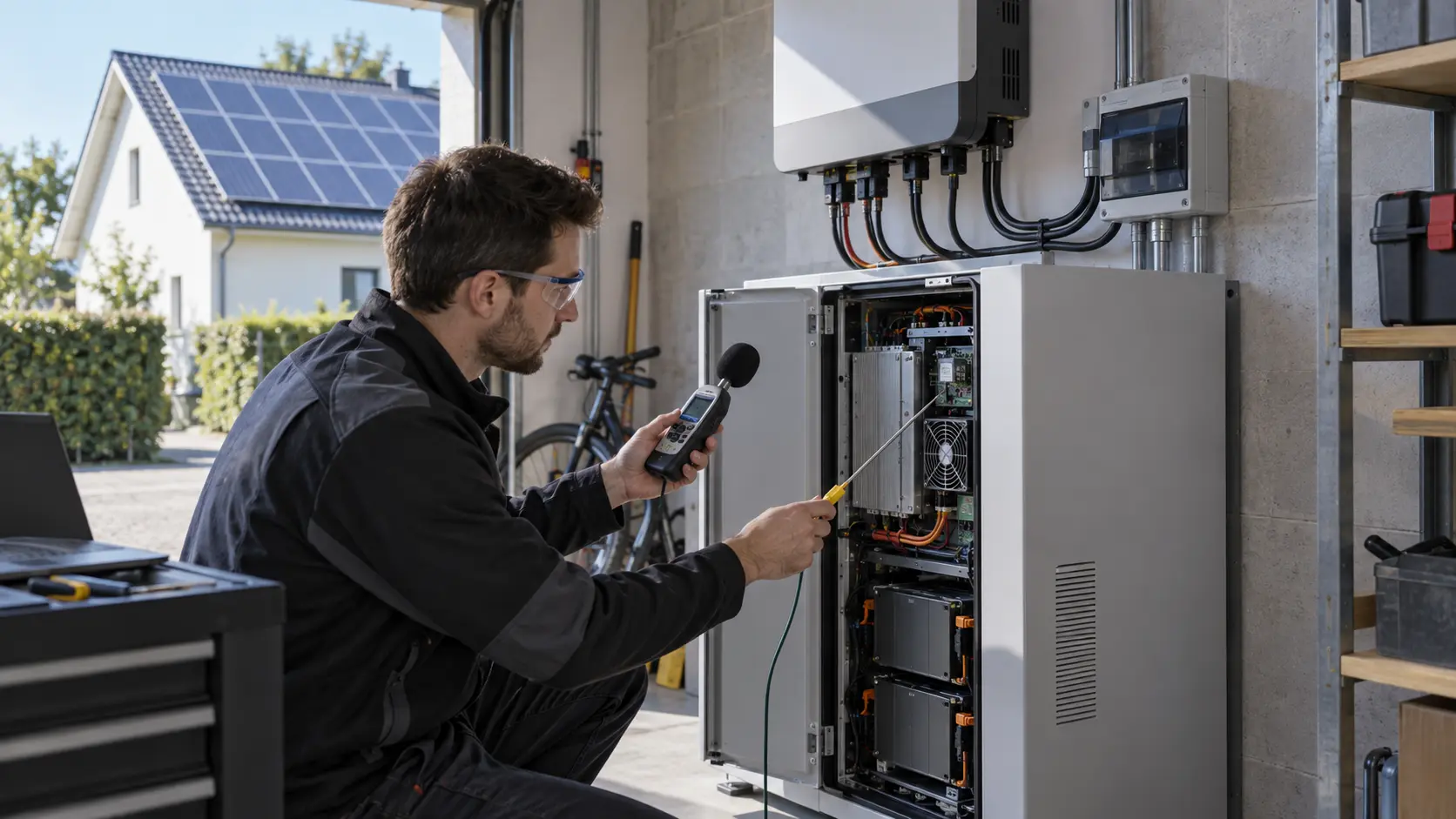
Before the tender configuration is released, test the fan and control logic with the representative filter, grille, battery-module resistance and power supply. Measure airflow, static pressure, current, speed feedback, temperature response and noise at each control stage. Repeat the checks after a fan fault, blocked or loaded filter, reduced supply voltage and a restart from cold conditions.
The safety functions must remain clearly separated. Battery thermal management, thermal-runaway detection, gas monitoring, fire protection and emergency ventilation are system-level responsibilities defined by the battery and installation design. Depending on the hazard analysis and applicable requirements, ventilation may need an independent power path and a controlled response after a confirmed abnormal event; simply forcing the cooling fan to 100% is not a universal safe action.
Once the customer approves the behavior, freeze the sample as a production specification: fan curve at the cabinet operating point, temperature thresholds, PWM or voltage limits, feedback timing, LED and host signals, connector drawing, installation orientation, inspection items and fault-response table. That package turns a tender concept into a repeatable fan and control solution. For a formal ESS safety or compliance decision, the cooling evidence must remain part of the complete battery, enclosure, controls and installation assessment rather than being treated as a standalone fan certificate.
- Validate each speed stage against the installed cabinet resistance.
- Test stall, lost feedback, blocked filter, low voltage and cold restart behavior.
- Keep normal cooling control separate from BMS, gas, fire and emergency-ventilation decisions.
- Freeze the approved fan curve, thresholds, interfaces and fault-response table for production.
Engineer Questions About This Case
For an energy-storage cabinet, a controllable and observable cooling subsystem matters as much as its airflow capacity.
Q: What did the tender require beyond airflow? A: It required a cooling subsystem that could change speed, provide useful status information and integrate with the cabinet control strategy. A larger free-air CFM number alone did not answer the requirement.
Q: What control signals should be reviewed? A: Confirm the exact command and feedback interface, including PWM behavior, FG or RD interpretation, voltage range, startup response, fault visibility and the controller reaction to a missing or abnormal signal.
Q: How should the cabinet validate a fan-control design? A: Test normal speed control, low-voltage operation, loss-of-signal behavior, restart, temperature response and representative airflow resistance with the cabinet controller connected.
Q: Is the cabinet fan part of the thermal-runaway safety system? A: It supports the normal operating envelope, but it is not a substitute for BMS protection, gas detection, suppression, isolation or emergency ventilation.
Q: What should be documented before production? A: Freeze the fan interface, control limits, feedback interpretation, alarm behavior, operating-point requirement and the acceptance test used for the cabinet assembly.
- Separate project-reported values from general engineering guidance.
- Record the test condition, mounting, voltage, speed and measurement method with every result.
- Use the case questions to define the next sample or validation step.
Discuss an energy-storage cooling requirement
For cabinet cooling projects, share the temperature thresholds, available supply, control signals, fault response and installation constraints. These inputs allow a fan and control approach to be reviewed as one system.