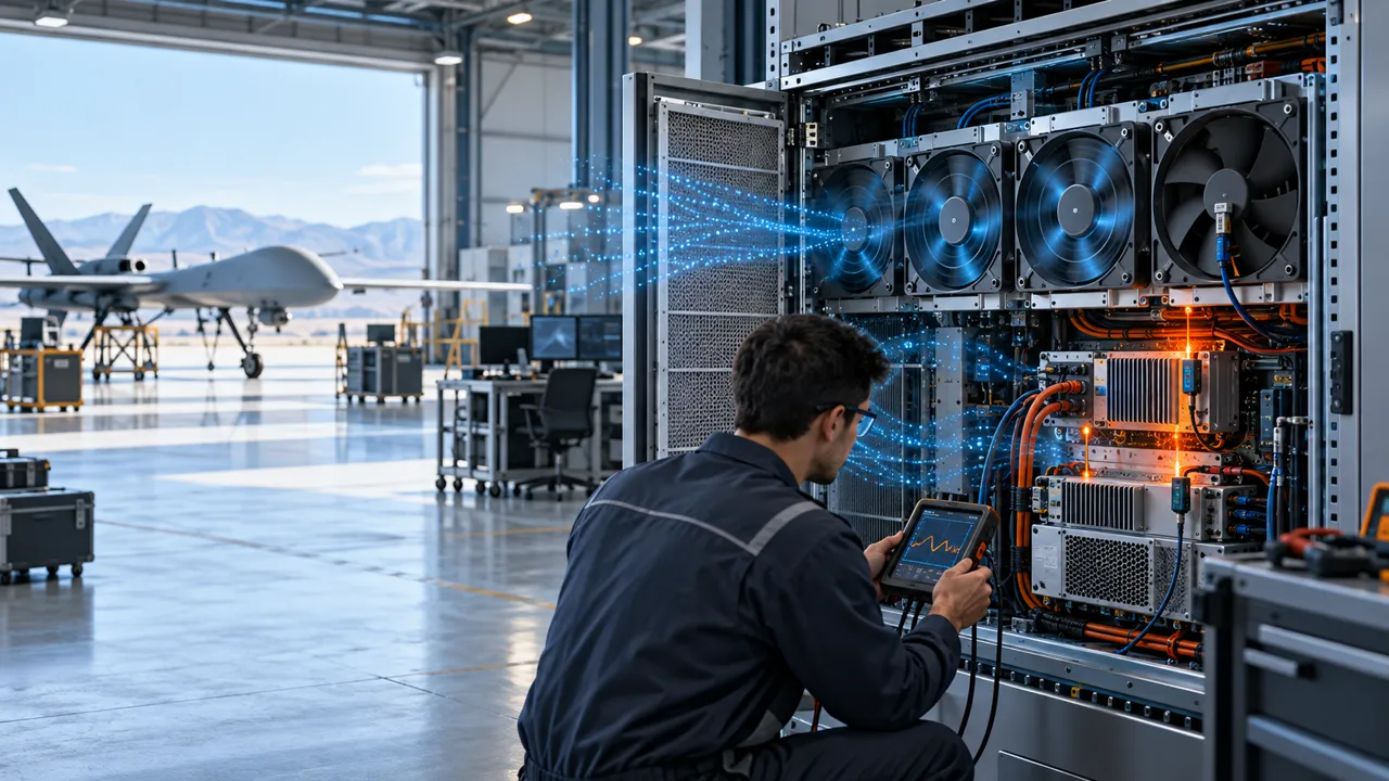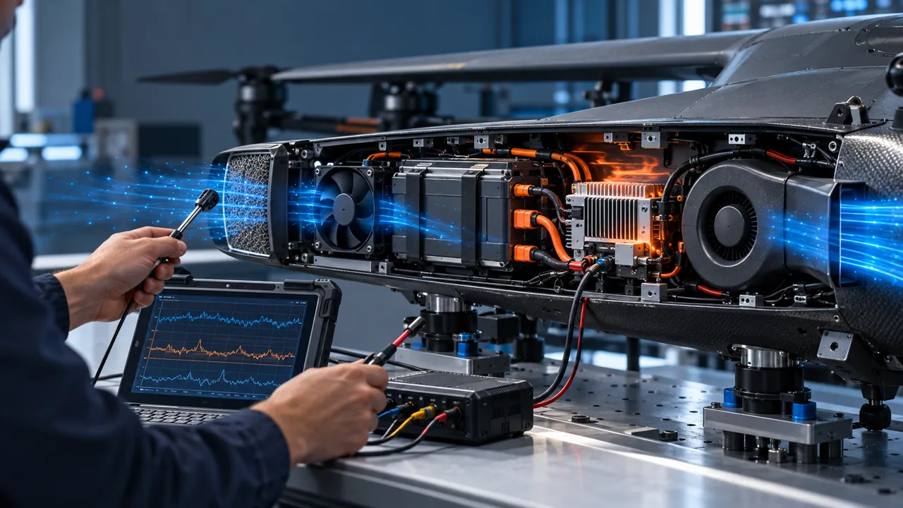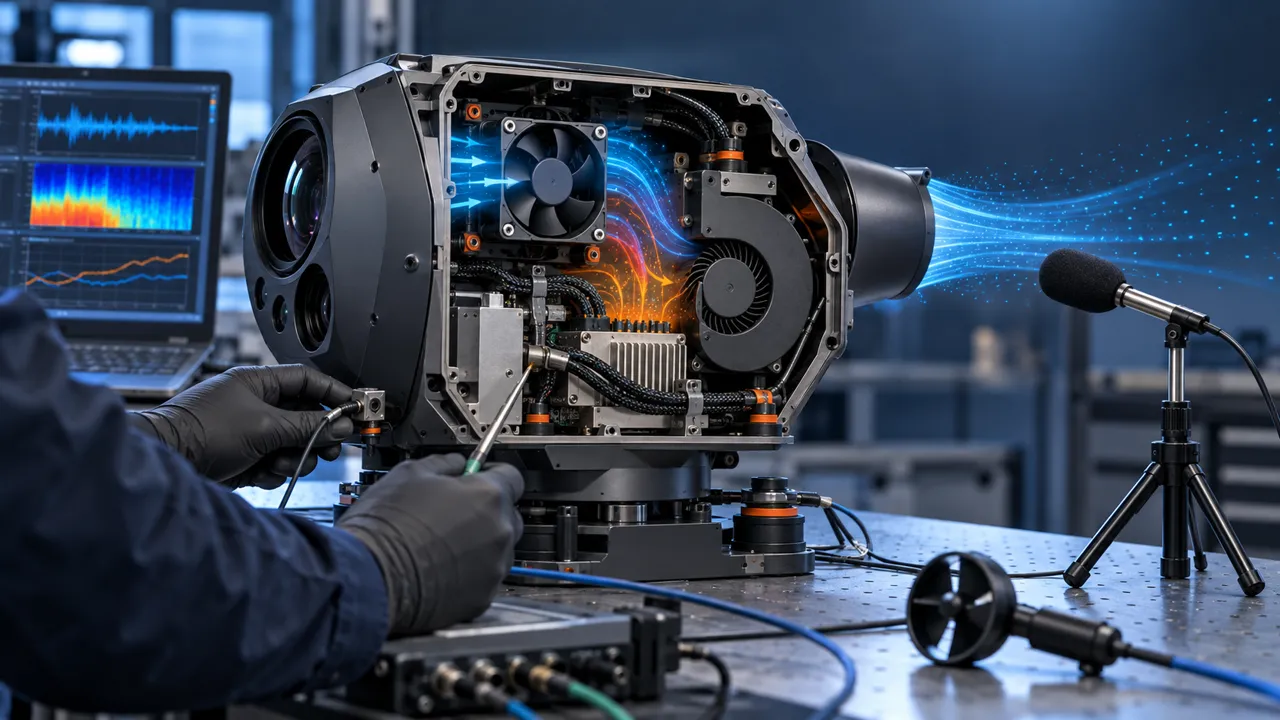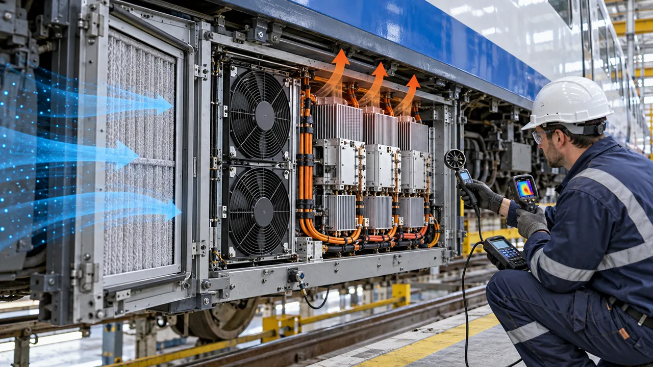
The Railway Converter Problem Was an Installed-System Problem
An anonymised rail-equipment development team needed to validate cooling for a traction-converter cabinet exposed to vibration, dust, moisture and changing pressure resistance.
A traction converter turns electrical energy into the controlled power needed by a vehicle drive system. Its semiconductor modules, capacitors, bus structures and control electronics generate heat inside a constrained enclosure. The cooling fan is only one part of the thermal path. Filters, grilles, duct turns, heatsinks, seals, cable routes and the vehicle mounting structure all influence the operating point that the fan actually sees.
The engineering question was not whether a catalogue fan had a high free-air CFM number. The question was whether a candidate fan could deliver the required airflow at the installed pressure, over the temperature and vibration envelope, while its feedback and fault response remained useful to the converter controller.
The project pattern described here is anonymised. It is a validation method, not a claim that any listed fan is approved for a railway vehicle, a traction converter or a safety-related function. Final system design, vehicle qualification, electrical safety and railway compliance remain with the responsible system integrator and vehicle programme.
Start by separating the thermal requirement from the fan requirement. The converter owner defines allowable semiconductor and capacitor temperatures, the operating load profile and the permitted temperature rise. The cooling engineer then translates those limits into an airflow and pressure target for the actual assembly. This avoids the common failure mode in which a fan is purchased first and the enclosure is expected to accommodate it later.
The same discipline applies to redundancy. If the system has more than one fan, state whether the requirement is normal parallel operation, a reduced-power degraded mode or a true N+1 condition. A failed fan can create bypass flow or recirculation through an open module. The survivor fan must be tested with the failed path in the exact state expected in service.
Why Rail Traction Cooling Cannot Be Chosen from Free-Air CFM
A vehicle-mounted converter sees a pressure network, not an open laboratory outlet.
The filter may be clean at commissioning and partially loaded after service. A grille can add resistance when its open area is smaller than the fan frame. A heatsink can require a particular flow direction. A duct or baffle can create a local separation zone. The fan curve intersects the complete system-resistance curve at one installed operating point, and that point changes when any of those elements changes.
Free-air airflow is still useful as a catalogue reference, but it is not the acceptance value. A candidate should be compared at the required airflow and the pressure drop of the real filter, grille, heatsink and enclosure. If the converter controller increases PWM when the cabinet gets warm, the test should also record whether the added speed produces useful airflow or mainly adds noise, power and vibration.
The first design review therefore records heat load, allowable component temperature, inlet temperature, altitude basis, fan envelope, quantity, redundancy assumption, filter state, pressure budget and control interface. Without those inputs, a recommendation is a family shortlist, not a final fan selection.
Build the Pressure Budget Before Comparing Fan Samples
The pressure budget should expose where margin is being consumed and which restriction can be changed.
List the pressure losses in the direction of flow: external inlet protection, filter, grille, fan guard, duct or plenum, heatsink, module clearance and exhaust path. Measure or estimate each item at the same airflow basis. Keep the clean and loaded filter cases separate. If the cabinet can be operated in either direction, test the intended direction and any reverse-flow condition created by neighbouring fans or vehicle airflow.
An illustrative calculation makes the logic clear. Suppose the target airflow is 0.18 m³/s and the clean path measures 70 Pa across the filter, 90 Pa through the heat exchanger and 60 Pa through the enclosure path. The fan must meet about 220 Pa at that airflow before a design margin is discussed. If a loaded filter adds 80 Pa, the required point becomes about 300 Pa. These are planning numbers only, not product performance data.
The candidate fan should have usable pressure head at the loaded point, not just a high shut-off pressure. A large frame can provide more flow but may not fit the cabinet or its mounting isolation. A smaller high-speed fan may fit but create a vibration or acoustic problem. The correct decision is the intersection of mechanical envelope, pressure, temperature, control and maintenance requirements.
Keep units consistent in the test record. Static pressure may be shown in Pa, mmH₂O or inH₂O, while airflow may be shown in m³/min or CFM. The conversion is useful for communication, but acceptance should use one declared unit system and one clearly defined measurement location. Do not combine a free-air CFM value from a catalogue with a pressure value measured at a different duct condition and call the pair an operating point.
When a candidate is close to the edge of its curve, small installation details matter. A rounded inlet, a sharp grille, a gap around the frame, or a short diffuser can move the measured result. Photograph the test assembly, record the fan orientation and keep the pressure taps in fixed locations. Repeatability is part of the evidence, especially when comparing samples from different suppliers.
Filter Loading, Dust and Moisture Change the Duty
Underbody and roof-mounted equipment cannot treat the clean commissioning state as the whole service life.
Dust from trackside environments can load a filter or deposit on a heatsink. Moisture can change the filter condition, create a corrosion concern or alter the service procedure. Salt exposure may be relevant for coastal routes or winter road-treatment environments. The exact environmental qualification belongs to the vehicle and equipment programme; the fan review needs the actual environment, cleaning method and enclosure protection assumptions rather than a generic label such as outdoor.
Define at least a clean state, a controlled loaded state and the proposed service-limit state. Record filter media, face area, sealing method, pressure drop and how loading is reproduced. A pressure sensor should not be used as the only evidence: bypass around a badly sealed filter can lower measured pressure while allowing contamination into the cabinet.
During the loaded test, record airflow, filter differential pressure, fan command, current, inlet temperature, heatsink temperature and fault feedback. If the controller raises speed, confirm that the measured airflow follows. A stable FG signal proves rotation feedback, not adequate cooling. Thermal margin and airflow at the real pressure remain the acceptance evidence.
Plan the maintenance trigger with the operator rather than choosing an arbitrary percentage. A pressure threshold may be practical when the filter is accessible and the sensor can be protected. A thermal or airflow threshold may be more meaningful when loading is uneven. Whichever trigger is selected, verify it against the response time of the controller and the time needed to stop, inspect and service the vehicle equipment.
Do not use moisture or salt exposure as a marketing adjective. Describe the actual route, enclosure, drainage, cleaning and storage conditions. The fan supplier needs to know whether condensation can occur during a cold-to-warm transition, whether the fan sees direct spray, and whether the filter can retain water. These details influence the mechanical and electrical review, but they do not replace the system integrator's environmental qualification.
High and Low Temperature: Check Startup and Recovery
A fan that runs after warm-up may still fail the cold-start, restart or transient requirement of a traction converter.
Temperature changes affect bearing behaviour, lubricant viscosity, winding resistance, electronics and air density. Air density also changes the mass flow associated with a volumetric airflow value. The test plan should define the cold-start temperature, hot operating temperature, soak time, supply-voltage tolerance, PWM command at startup and the time allowed for feedback to become valid.
Repeat startup after a cold soak, after a short power interruption and after a controller reset. Record startup current, time to rotation, time to valid FG or RD feedback, any repeated-start behaviour and the recovery of airflow. If the converter uses a minimum PWM threshold, validate that threshold with the real filter and pressure path, not on an unloaded bench.
For high temperature, run the converter or a representative thermal load at the specified inlet condition and observe whether the fan reaches a stable duty. Do not infer final thermal acceptance from a fan speed number. The relevant result is the relationship between load, installed airflow, component temperature and controller response at the expected density and supply condition.
A restart test should include realistic power sequencing. Some vehicle auxiliaries do not rise cleanly from zero, and the fan supply can see a short dip while contactors or converters change state. Record the supply at the fan terminals rather than only at the upstream power source. A connector drop or harness resistance can make an apparently suitable fan fail to start even when the nominal supply value looks correct.
Where the design uses speed control, define the behaviour below the normal operating command. A fan may have a minimum reliable speed, a start boost or a delay before valid feedback. The converter software should not assume that a zero PWM command means the rotor stops immediately, nor should it treat a brief feedback delay during restart as a permanent fan failure without a defined retry strategy.
Vibration, Shock and Mounting Are Part of Fan Validation
A reliable rotor can still create a system problem if the mounting, cable route or enclosure panel amplifies vibration.
The fan sample should be evaluated in the intended orientation and mounting stack. Check screw torque, isolator compression, panel flatness, bracket stiffness, guard clearance and the distance between the fan and any flexible duct. A fan mounted on a thin panel can excite a structural mode even when the fan itself is balanced. A cable touching the frame can turn a small vibration into an audible rattle or an intermittent insulation concern.
Measure vibration at the fan frame, cabinet panel and nearby sensitive component. Compare the spectrum before and after installation. Look for a change at rotational frequency and harmonics, blade-pass frequency, bearing-related components or a panel resonance. The exact limits must come from the vehicle or equipment programme; this article does not invent a railway acceptance limit.
Apply the planned vibration and shock sequence to the representative assembly, then repeat startup, speed command, FG/RD feedback, airflow and thermal checks. Inspect fasteners, connector retention, cable strain relief and the fan frame after the sequence. A visual check alone is not enough if the system has a measurable vibration history.
Mounting also affects the pressure result. A flexible seal that improves leakage control can change the load transferred to the panel, while a stiff bracket can reduce movement but transmit more vibration. Record the mounting solution as part of the fan sample, including any isolators, washers, thread retention and torque. A product result without the mounting stack is difficult to reproduce.
If a tonal noise or vibration peak appears, do not immediately reduce speed and call the problem solved. First check whether the peak comes from the fan, the panel, a grille, the cable route or a blade-pass interaction with an upstream obstruction. The final remedy may be a clearance change, a bracket change, a different control profile or a fan geometry revision.

PWM, FG and RD: Verify the Interface, Not Just the Wires
The converter controller needs a known electrical behaviour during normal speed control, startup, stall and a fan fault.
Document the supply range, PWM frequency and logic levels, FG pulse expectation, RD or alarm polarity, connector pinout and grounding arrangement. Do not assume two fans with the same frame size use the same control convention. Confirm whether the controller commands a minimum speed, whether the fan starts from zero command and how it behaves when PWM is removed.
Use an oscilloscope or suitable logger to capture PWM command, supply voltage, current, FG or tach output and RD or fault output together. Test startup, speed steps, rapid command changes, supply dips, controller reset and an intentionally stopped or disconnected fan where safe. Check that the controller does not interpret a missing pulse as a healthy low-speed state.
The aim is a fault decision that is useful to the converter system: fan not rotating, feedback missing, airflow below requirement, over-temperature or a wiring fault should not be silently collapsed into one ambiguous alarm. MEGA Tech can review the fan-side interface and sample behaviour; the system integrator owns the converter protection logic and safety response.
A Practical Sample Validation Sequence
A staged sample plan reduces the risk of changing several variables at once.
Stage one is document review: heat load, allowable temperatures, airflow and static pressure, fan envelope, voltage, control, filter, mounting, environment and service assumptions. Stage two is a bench check of the candidate fan with the agreed supply and control interface. Record the catalogue curve reference and identify the points that still require installed testing.
Stage three installs the fan in the representative filter, grille, heatsink and enclosure. Measure the clean-state operating point and confirm the pressure taps, airflow instrument, temperature sensors and electrical logging. Stage four repeats the test with the loaded filter and planned service-limit state. Stage five applies the environmental and vibration sequence defined by the responsible programme, then repeats the functional checks.
The release record should contain a clear pass or action for each condition: airflow at pressure, component temperature, startup, restart, current, noise, vibration, PWM response, FG/RD feedback, fault detection, connector retention and post-test inspection. If one item is not yet proven, keep the fan as an engineering sample rather than presenting it as a production-approved solution.
A useful report includes the test configuration as carefully as the result. Record instrument model and calibration status, sensor positions, ambient condition, supply wiring, fan serial or sample identifier, filter condition, workload step and time history. If the result is a range, show the range and the reason for it. A single rounded value can hide a transient or a measurement uncertainty that matters to the converter controller.
The final design review should also list open risks. Examples include an unverified service-limit filter, an untested cold restart, an unresolved connector definition, an unconfirmed vibration limit or a pressure tap that cannot be retained in production. Keeping these visible is more useful than declaring a fan approved because the first clean-bench test was successful.
Candidate Product Directions for the First Review
These catalogue families are starting points for a pressure-and-envelope review, not automatic railway recommendations.
A 120 × 120 × 38 mm DC axial fan candidate can be useful when the converter has a compact mounting envelope and a moderate-to-high pressure requirement. Review its actual voltage, speed, airflow, pressure, noise and control variants against the loaded filter and heatsink duty. Do not select from frame size alone.
A 172 × 150 × 51 mm DC axial fan candidate may be considered when a larger face area and a deeper fan envelope are available. Its larger outline can change grille velocity and pressure loss, so the complete inlet and outlet geometry must be tested. A 200 × 200 × 60 mm DC axial fan candidate can be considered for a larger enclosure or higher airflow concept, subject to the same installed-duty checks.
Use the MEGA Tech fan-selection tool to create a first shortlist, then send the required airflow and static pressure at that airflow, size, voltage, quantity, control, connector, noise, temperature, altitude, environment, vibration and life assumption for a sample discussion. The links below are product information routes; they are not certificates of railway suitability.
How MEGA Tech Supports a Traction-Converter Fan Review
MEGA Tech is a custom cooling-fan manufacturer focused on the fan and air-path portion of the engineering decision.
We develop and manufacture custom cooling fans and can review DC axial fans and compact centrifugal blowers against the customer's installed operating point. The work can include fan selection, air-path review, sample validation and the preparation of a specification for volume production. The fan is selected by airflow, static pressure, temperature, control, noise, vibration and envelope—not by a familiar part number or outline dimension alone.
For a useful review, provide the converter heat load, required airflow and static pressure at that airflow, inlet-temperature and altitude basis, voltage tolerance, PWM/FG/RD interface, connector, fan quantity, envelope, filter and grille information, noise target, vibration and shock assumptions, environmental exposure, service interval and life assumption. Photos or drawings of the mounting stack and cable route are especially valuable when vibration is a concern.
Our boundary is equally important: MEGA Tech does not supply complete traction converters, railway vehicles, coils, liquid loops, pumps, control cabinets, railway safety systems or final vehicle certification. Those remain with the responsible system integrator and approval organization. We supply the custom fan engineering and sample path that the integrator can validate in its own system.
Engineer Questions for a Railway Converter Design Review
Use these questions to expose hidden assumptions before freezing a fan or filter specification.
Q: Is a high free-air CFM enough? A: No. Compare the fan at the required airflow and the pressure of the clean and loaded installed air path.
Q: Should the fan be approved from a catalogue curve? A: The curve is a starting point. The representative filter, grille, heatsink, enclosure and control interface still require validation.
Q: Does FG feedback prove cooling? A: No. It proves the feedback signal is present. Correlate it with airflow, pressure, temperature and the controller's fault threshold.
Q: What should be checked after vibration and shock? A: Repeat startup, airflow, temperature, current, PWM, FG/RD and fault checks, then inspect fasteners, connector retention, cable strain relief and clearances.
Q: Do 120, 172 and 200 mm candidates mean the application is covered? A: They are candidate directions only. The final choice depends on the required duty, envelope, pressure margin, environment, control and sample results.
Q: Can MEGA Tech provide a sample recommendation? A: Yes, after reviewing the operating point and constraints. Send fan size, voltage, airflow/static-pressure target, quantity, control, noise and environment.
Need a Traction-Converter Fan Sample Review?
Send the installed airflow and pressure target, fan envelope, voltage, quantity, control interface, filter condition, noise target, vibration assumptions and operating environment.
Include the current fan or candidate part number if there is one, converter heat-load estimate, inlet and component temperature limits, clean and loaded filter data, grille and heatsink drawings, mounting and cable-route photos, PWM/FG/RD details, startup and restart requirements, and the validation sequence expected by the responsible integrator. MEGA Tech can then review whether a catalogue candidate or a custom cooling-fan sample is the right next step.