The Battery Bay Passed the Bench Test and Failed the Mission Profile
An anonymised UAV team needed a compact cooling fan for a battery and ESC compartment that changed from cruise to peak power in minutes.
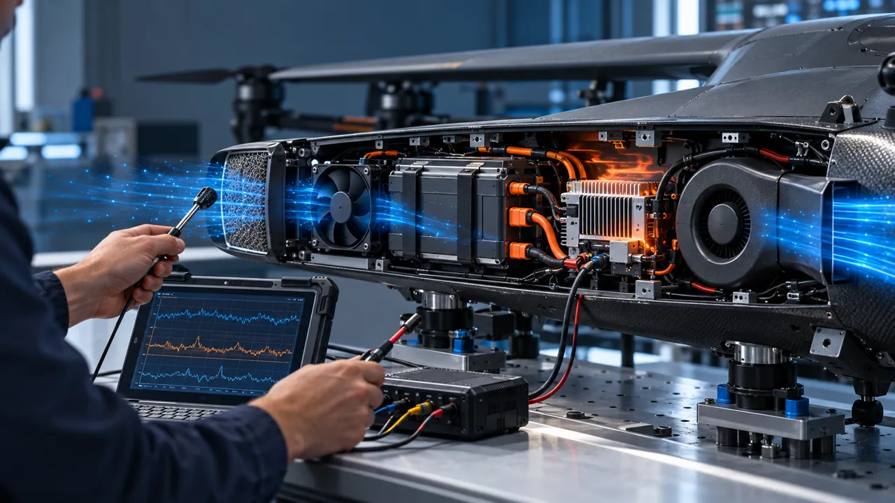
The aircraft used a confined bay containing battery modules, power conversion, ESC electronics and wiring. A short room-temperature test showed acceptable temperatures, but the same arrangement accumulated heat during repeated high-power operation. The inlet filter became warmer, the ESC hotspot rose faster than the average bay temperature, and the available battery energy made continuous high fan speed unattractive.
The problem was not solved by choosing the largest free-air CFM number. The team had to account for the installed pressure loss, air density at altitude, inlet temperature, battery discharge heat, ESC switching heat, startup behavior and the response after a fan fault. The fan also had to fit the aircraft mass and power envelope without creating a new structural or cable-clearance problem.
The customer and measured acceptance values remain confidential. This case records the engineering workflow used to turn a variable UAV duty into a repeatable fan sample and a test plan that the payload or aircraft team could own.
Separate Battery Heat, ESC Heat and Inlet Air Temperature
A single bay temperature hides the source of the thermal margin loss.
Battery cells and ESC components do not create the same heat pattern. The battery can release heat over a long discharge period, while the ESC can create a sharper local hotspot during high current or rapid throttle changes. If the fan draws air from a warm recirculation zone, the measured inlet temperature may already include heat from the battery or motor-side structure.
The review therefore placed sensors at the air inlet, battery surface, ESC heat sink, local outlet and ambient reference. The result was a time-aligned record of when each component became limiting. The fan command, current, speed feedback and pressure estimate were logged with the thermal channels so a temperature change could be related to an actual operating point.
This separation also protects the design from an incorrect fix. More airflow through the ESC cannot solve a battery heat problem if the battery is isolated from the flow. Likewise, lowering the average bay temperature does not prove that the ESC junction or heat sink has enough margin. The air path must cross the intended heat source and the sensors must be located where the decision is made.
| Measurement | What it reveals | Design action |
|---|---|---|
| Inlet air | Density and available cooling basis | Recalculate mass flow and heat capacity |
| Battery surface | Long-duration heat accumulation | Check discharge duty and flow coverage |
| ESC heat sink | Local peak during high current | Tune pressure and outlet direction |
| Outlet air | Actual heat carried away | Compare with expected air path |
| Ambient reference | Test boundary condition | Repeat the same duty at each condition |
Use Installed Pressure Instead of Free-Air CFM
The candidate fan was compared at the pressure created by the filter, grille, duct and outlet.
The battery bay had a short but restrictive path. The inlet mesh and filter added resistance, the fan sat close to a bend, and the outlet opening changed the pressure distribution across the ESC heat sink. A free-air catalogue value could not describe the resulting operating point. The team measured the pressure difference around the fan and checked the airflow at the heat source.
The selection review compared a compact axial fan with a small centrifugal blower. An axial fan can be efficient in a short, open path; a blower can be useful when the air must turn through a narrow duct. Neither type is automatically correct. The installed system curve, available envelope, mass, voltage and control interface decide which sample deserves a test.
The first sample was not accepted because it had the highest nominal airflow. It was accepted for the next test because it had enough pressure margin at the required flow, a compatible electrical interface and a package that could be mounted without blocking the battery or the wiring harness. The final decision still depended on the complete thermal duty.

Account for Altitude and Hot Inlet Air
The aircraft mission defined the air-density basis instead of assuming sea-level laboratory air.
At higher altitude, the same volumetric flow contains less mass of air. The heat carried per unit time therefore changes even if the fan speed and measured CFM appear unchanged. The system pressure and fan curve can also shift with density. The calculation must state the temperature and altitude basis before a thermal result is compared with a sea-level result.
Hot inlet air reduces the temperature difference available between the electronics and the cooling stream. A fan can still move the same volume while providing less useful heat capacity. The test matrix included the hottest expected inlet condition and the altitude condition that the aircraft team considered credible, rather than applying an unspecified “high altitude” factor.
The useful output was a margin map: fan command, installed airflow, component temperature and energy draw at each mission state. It did not turn one calculation into a universal UAV guarantee. Any change to battery chemistry, motor power, duct, altitude range or inlet location can move the required fan operating point.
Balance Cooling Power Against Mission Energy
Fan power was treated as a mission-level energy cost, not an isolated electrical specification.
A fan that runs at high speed for the entire flight can consume energy that the aircraft needs for propulsion, payload processing or reserve. The review recorded fan voltage, current and command alongside the mission phases. If cooling demand rises only during peak ESC power, a controlled speed schedule may preserve energy while keeping the hotspot inside its limit.
The speed schedule was not allowed to become a blind duty-cycle rule. The controller needed a temperature or power basis, a minimum reliable startup command and a response to a missing feedback signal. A low command that saves energy but stalls the fan is not a valid energy optimization.
The team compared continuous cooling, staged speed and event-driven response. The best choice depended on the battery and ESC thermal time constants, the aircraft controller and the mission-abort strategy. MEGA Tech can tune the fan-side command and feedback behavior, while the aircraft owner defines the system energy and safety decisions.
Validate Cold Start, Restart and Fan Fault States
A flight-ready cooling design must explain what happens before the fan reaches steady speed and after it stops.
Cold startup can occur after storage, a rapid turnaround or a power interruption. The test recorded supply voltage, current, time to valid feedback and airflow development. A fan that starts on a laboratory supply may fail when the aircraft harness has a voltage drop or when the controller limits startup current.
Repeated restart was tested because a battery or ESC protection event can cause the fan to stop and restart while the bay is already hot. The controller response was checked for false healthy feedback, delayed tach pulses and a command that remained below the reliable start threshold. The acceptance rule belonged to the payload or aircraft requirements, not to a generic fan label.
A fan fault also needs a defined system action. The aircraft may reduce power, limit payload operation, issue a warning or return to a safe state. The fan supplier can provide feedback characteristics and a sample for installed validation, but the aircraft manufacturer owns the flight-safety logic and mission decision.
| State | Record | Pass question |
|---|---|---|
| Cold start | Supply, current, time to feedback | Does the fan start at the real minimum voltage? |
| Cruise | Inlet, component temperatures, command | Is cooling stable without unnecessary energy? |
| Peak power | ESC hotspot, pressure, airflow, current | Does the installed point retain thermal margin? |
| Restart | Stop, restart, feedback and temperature | Does recovery happen without a hidden stall? |
| Fault | Feedback loss and controller action | Is the aircraft response explicit? |
Protect the Inlet, Outlet and Harness From Mission Conditions
The fan sample was checked with the restrictions and wiring that the aircraft would actually use.
Dust, spray, service access and vibration can change the inlet resistance during operation. A clean-bench result is not enough if the aircraft uses a filter or mesh that loads quickly. The team checked the inlet condition, filter clearance and service trigger, then repeated the pressure and temperature measurements with the intended restriction installed.
The outlet was checked for recirculation into the inlet and for hot air impinging on a nearby battery or cable. The harness was routed with enough clearance that movement, thermal expansion and assembly variation could not bring it into the fan path. A cable that contacts the frame can also create a vibration path and a new failure mode.
The resulting drawing identified no-contact zones, sensor locations, cable supports, filter access and the direction of the intended flow. Those details are often more important than changing from one nominal fan size to another. The sample had to fit the complete aircraft bay, not an isolated product cut-out.
Result: A Mission-Based Cooling Sample and Margin Map
The design review closed when the aircraft team could connect each thermal result to a mission state and an installed fan condition.
The release record captured the fan envelope, mass, voltage range, current, command, feedback, pressure reference, airflow measurement point, inlet condition, battery and ESC temperatures, altitude basis and restart behavior. It also recorded the filter and harness configuration so a later mechanical change could be recognized as a new validation trigger.
The transferable result was a method rather than an unqualified performance claim. The team knew when the bay was limited by inlet temperature, when the ESC was limited by local pressure, when the fan command was wasting energy and what action followed a fan fault. That knowledge supported a more useful trade-off between thermal margin, mass and mission endurance.
A different aircraft, battery, ESC, filter or altitude range would require its own sample check. The correct candidate is selected at the actual operating point and then validated in the customer assembly. Matching the outline size alone does not establish equivalent cooling or mission reliability.
How MEGA Tech Supports Custom UAV Cooling Fans
We help UAV teams turn a battery and ESC thermal duty into a fan sample that can be measured in the real aircraft bay.
MEGA Tech develops and manufactures custom cooling fans, including compact DC axial fans and centrifugal blower options for restrictive air paths. Our work can cover fan selection, air-path review, sample validation and volume production. We select from airflow and static pressure at the operating point, not from a part number or free-air CFM alone.
For a first review, send the battery and ESC heat load by mission state, inlet temperature and altitude basis, required airflow and pressure, fan envelope and mass limit, voltage tolerance, PWM/FG/RD or alarm interface, connector and harness route, filter or grille, mounting, noise and vibration limits, quantity and life assumption. A sample can then be evaluated on the customer assembly.
We do not supply complete UAVs, batteries, ESCs, airframes, flight controllers, coils, liquid loops, system controllers or flight-safety functions. Those remain with the aircraft and system integrators. Start with the fan selection tool, review a 40 x 40 x 10 mm candidate, or request a sample on WhatsApp.
Engineer FAQ
These questions usually decide whether a battery and ESC fan sample needs another design iteration.
Q: Is a lower fan current always better for flight endurance? A: No. If the lower command stalls or loses pressure margin, the hotter electronics can cost more energy or force a power limit. Compare fan energy with the complete thermal response.
Q: Can sea-level CFM be used at altitude? A: It can be a catalogue reference, but the thermal calculation must state air density and temperature. Installed pressure and heat capacity need the mission basis.
Q: Should the battery and ESC share one airflow path? A: Sometimes, but only after checking heat order, recirculation and local hotspots. One path can heat the downstream component or hide a restriction.
Q: What should FG or RD do after a fan stops? A: The aircraft or payload controller must define the response. It may warn, limit power or change mission state; the fan signal alone is not a flight-safety decision.
Q: What does MEGA Tech need for a first sample? A: Heat load by mission state, airflow and pressure, voltage, altitude, inlet temperature, envelope, control, noise, environment, quantity and the actual filter, harness and duct.
Questions for a Design Review
Use this checklist with thermal, electrical, mechanical, controls and flight-operation teams before freezing the battery-bay fan.
- What are the battery and ESC heat loads during cruise, peak power, repeated restart and hot turnaround?
- What airflow and static pressure are required at the real inlet temperature and altitude?
- Where does the air go after the fan, and which component is downstream of the battery heat?
- What filter, grille, duct bend and outlet restriction are included in the installed test?
- What fan voltage, current, command and feedback are available at the aircraft harness?
- What is the minimum reliable startup command at the lowest supply voltage and temperature?
- How much fan energy can the mission budget accept in each operating state?
- What does the controller do after missing FG/RD feedback or a stalled fan?
- Which change triggers a new sample: battery, ESC, duct, filter, altitude, controller or harness?