The Ground Station Was Cool Until the Filter Loaded
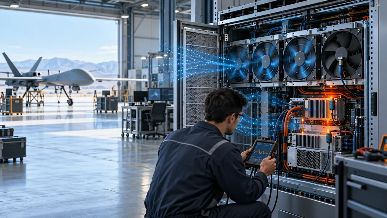
An anonymised UAV operations team needed reliable cooling for a ground station and hangar electronics rack exposed to dust, service interruptions and uneven fan loading.
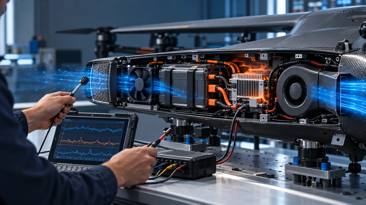
The equipment rack supported communications, charging supervision, mission data handling and power electronics. It passed a clean-filter test, but the inlet pressure increased after routine operation in the hangar. One fan then showed a speed-feedback fault while the rack was still carrying a high processing load. The surviving fans were running, yet the hottest power module no longer had the same airflow margin.
The design question was not simply whether the rack had enough total CFM. The team needed to know how much airflow reached the heat source after filter loading, whether one stopped fan caused reverse flow through an idle bay, and what alarm or maintenance action followed an FG or RD change. The answer had to be repeatable for a technician, not dependent on a single clean-bench demonstration.
The customer and measured acceptance values remain confidential. This case describes the engineering workflow for a fixed UAV ground station or hangar cabinet: measure the pressure path, validate the survivor state, and convert fan feedback into a maintenance decision.
Why a Fixed UAV Rack Needs More Than Total Airflow
Parallel fans can provide useful redundancy, but only if the enclosure and controls preserve the intended path after a fault.
A ground station cabinet can look steady while its internal pressure distribution changes. A loaded filter raises resistance, a blocked grille creates bypass, and a stopped fan can become a low-resistance path for reverse flow. The result is that the total fan-face airflow may remain plausible while one heat source receives too little air.
The review mapped the inlet, filter, fan array, heat sink, outlet and cable openings. It measured pressure at the filter and at the equipment zone, rather than using fan free-air data as the acceptance value. The team also checked whether a failed fan had a damper, shutter or other feature that prevented it from stealing flow from the running fans.
N+1 is therefore a system claim, not a label on a fan array. The design must state the failed condition, the remaining fan command, the loaded-filter basis, the inlet temperature and the temperature point that defines pass or fail.
| Question | Risk if ignored | Evidence |
|---|---|---|
| Filter condition | Clean test hides pressure rise | Differential pressure and airflow |
| One fan stopped | Idle bay leaks or reverses flow | Survivor flow and fault state |
| Feedback signal | Fault is noticed too late | FG/RD trace and alarm timing |
| Heat-source point | Average cabinet temperature hides hotspot | Local temperature and pressure |
| Service action | Alarm has no maintenance meaning | Trigger, owner and response time |
Map Filter Loading Before Choosing the Survivor Speed
The first engineering task was to record how the pressure path changed as the filter accumulated resistance.
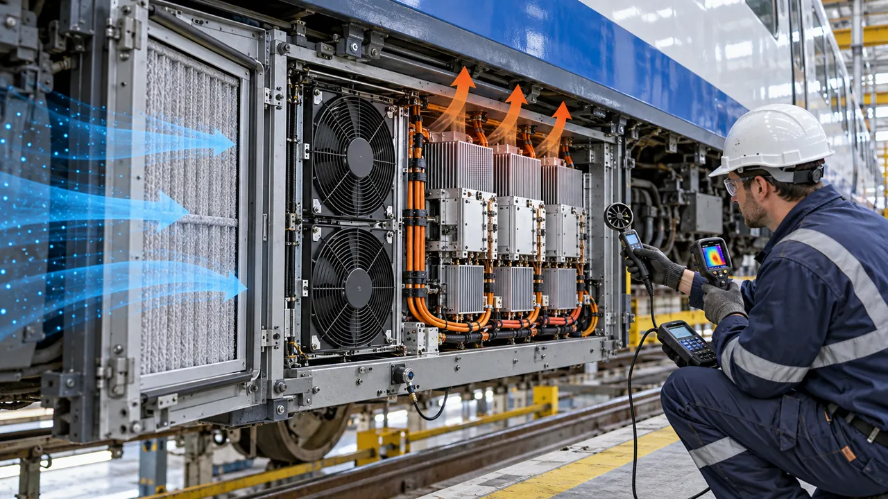
The team tested the rack with the intended filter, grille and service frame. Differential pressure was measured across the filter and the cabinet pressure was measured near the hottest electronics. This separated the pressure rise created by the filter from losses caused by the fan array, duct turns, heat sinks and outlet openings.
A filter does not need to be completely blocked to change the operating point. A moderate pressure increase can reduce airflow, move the fans to a different point on their curves and cause a controller to increase speed. The test recorded fan voltage, current, RPM, command, airflow and temperatures together so maintenance could see the trend rather than wait for an over-temperature event.
The service limit was defined around measurable pressure and thermal margin. It was not presented as a universal filter life. Dust type, operating hours, humidity, access frequency and the cabinet installation determine how quickly a filter reaches the chosen trigger.

Validate N+1 With One Fan Stopped
The failed-fan test used the same inlet restriction and operating duty as the normal rack.
The team stopped one fan at a controlled point and verified what happened to the remaining fans. It recorded the survivor fan speed, current, airflow, pressure and local equipment temperatures. It also checked whether the stopped fan freewheeled, reversed or created a bypass that pulled air away from the heat source.
The acceptance point was defined at the equipment, not at the fan array. If one power module remained below its agreed limit while the survivor fans operated within their electrical and mechanical limits, the condition could be considered a candidate for the next design review. If the survivor fans needed an unsafe speed or the hotspot rose too quickly, the array needed a different pressure margin, flow guide or fault-isolation feature.
The test was repeated with the filter at the selected service condition. A clean-filter N+1 pass did not substitute for a loaded-filter N+1 pass because the two states can have different reverse-flow and temperature behavior.
Use FG and RD Feedback as a Maintenance Signal
A fan alarm is useful only when the rack knows what the signal means and what action should follow.
The control review defined the expected FG or RD behavior, the valid-speed window, the missing-signal delay and the response to an intermittent signal. A single pulse loss should not create a false emergency, but repeated missing feedback should not be hidden by a long averaging window. The chosen timing depends on the fan, controller and thermal time constant.
The rack controller separated a warning from an immediate protective action. A warning could create a service ticket while the array retained margin; a critical state could reduce equipment load, transfer operation or request operator intervention. MEGA Tech can help confirm fan-side feedback and sample behavior, but the system integrator owns the cabinet protection and operations logic.
The maintenance record included the fan position, timestamp, command, feedback, filter pressure and local temperature. That made it possible to tell a fan fault from a blocked filter, loose connector or sensor problem.
Prevent Reverse Flow Through an Idle Fan
A stopped fan can become a leakage path when the running fans create a pressure difference across a shared plenum.
The array was checked for flow direction at each fan bay after one fan stopped. A simple smoke or particle visualization can show the direction, but the acceptance record used pressure and airflow measurements at defined points. The team compared the failed bay with and without the intended isolation feature and checked whether the running fans lost useful flow.
Reverse flow is not only a fan problem. Plenum geometry, grille resistance, duct seals, damper behavior and fan spacing can determine whether air bypasses the load. A layout that looks symmetrical on a drawing can have different resistance at the first and last bay. The test therefore included representative assembly tolerances and service-access panels.
The lesson was to specify the failure path explicitly. If a stopped fan is allowed to freewheel, the thermal model must include that behavior. If a damper or shutter is required, it must be checked for pressure loss, contamination, service access and repeatability.
| Condition | Measure | Decision |
|---|---|---|
| All fans running | Array pressure, flow and hotspot | Baseline operating point |
| One fan stopped | Idle-bay direction and survivor flow | Reverse-flow penalty is known |
| Loaded filter | Filter ΔP and survivor temperature | Maintenance basis is credible |
| Panel removed | Leakage and flow redistribution | Service state is understood |
| Feedback missing | Alarm delay and controller action | Fault response is explicit |
Keep Noise, Dust and Service Access in the Same Review
A rack that meets temperature limits but is difficult to service will eventually return to a degraded cooling state.
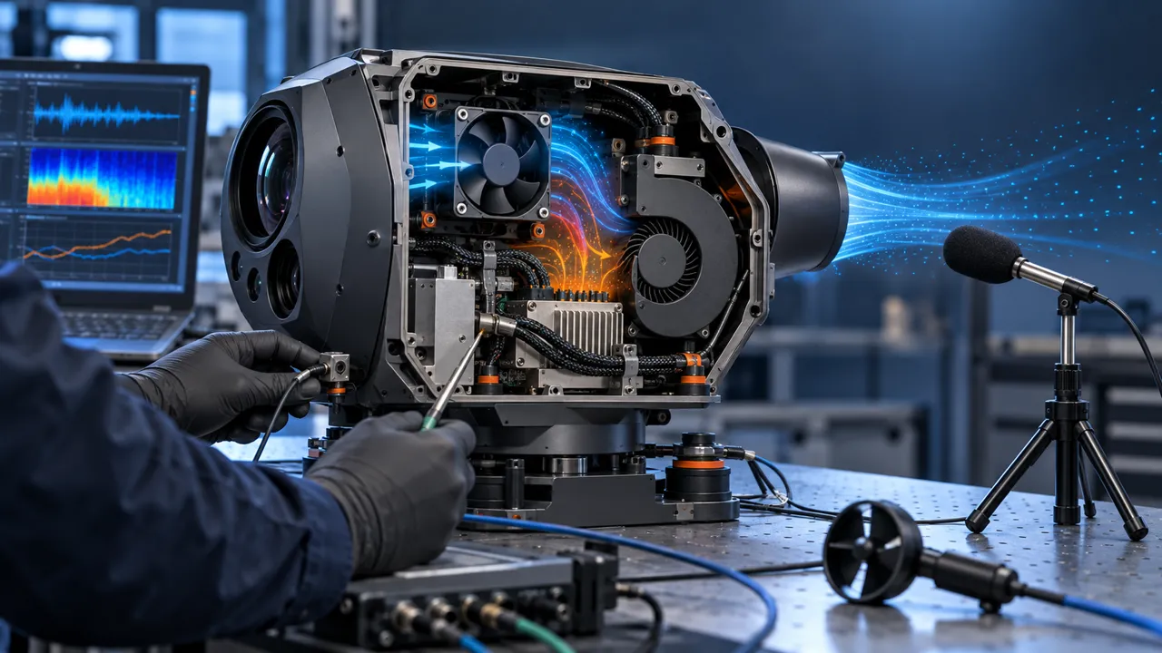
Ground stations and hangars can have operators nearby, so tonal noise and vibration matter even when the rack is not airborne. The fan array was checked at normal and survivor speeds, with the filter and access panels installed. The team recorded the measurement location because sound pressure depends strongly on distance, reflections and background equipment.
The filter frame was reviewed for removal clearance, seal compression and a repeatable installation. A filter that can be fitted with a gap changes the pressure path and can draw dust around the media. Cable routing and connector retention were also checked so service work did not disturb the fan or create a new bypass.
MEGA Tech can help tune the fan and interface around the installed pressure, voltage, control and noise requirements. The cabinet designer remains responsible for dust protection, operator safety, service procedures and the complete equipment enclosure.
Result: A Redundancy Plan Tied to Pressure and Temperature
The project closed when the rack team could connect a fan fault or filter trend to a measurable equipment response.
The release record contained the clean-filter baseline, the selected service pressure, the loaded-filter operating point, the one-fan-stop survivor state and the FG/RD response. It identified the pressure taps, temperature sensors, fan positions, control commands and maintenance owner. This allowed the operations team to distinguish a gradual filter problem from an immediate fan or connector fault.
The transferable result was not a blanket N+1 guarantee. It was a repeatable test boundary: at a stated inlet condition, filter pressure, fan command and equipment load, the rack had a defined response and a defined next action. A new fan, filter, plenum, heat load or installation site could require a new validation.
A custom fan sample is useful when it is tested in the real enclosure. The frame size alone does not prove survivor airflow, reverse-flow behavior, noise or service life.
How MEGA Tech Supports Ground-Station Cooling Fans
We help UAV operations and equipment teams move from a rack duty to a fan sample that can be tested in the real enclosure.
MEGA Tech develops and manufactures custom cooling fans, including DC axial fans and centrifugal blower options where the installed pressure path requires them. Our work can cover fan selection, air-path review, sample validation and volume production. We select from airflow and static pressure at the operating point, not a part number or free-air CFM alone.
For a first review, send the equipment heat load, inlet temperature, altitude or site basis, airflow and static-pressure target, filter and grille, fan envelope, voltage tolerance, PWM/FG/RD interface, connector, quantity, noise target, environment, maintenance interval and failure response. A sample can then be evaluated in the real rack with the filter, service panels and control system installed.
We do not supply complete UAVs, ground stations, cabinets, coils, liquid loops, controllers or emergency ventilation functions. Those remain with the equipment and system integrators. Start with the fan selection tool, review the DC axial fan range, or request a sample on WhatsApp.
Engineer FAQ
These questions usually decide whether a ground-station fan array needs another design iteration.
Q: Does N+1 mean the rack is safe with one fan stopped? A: Not by itself. The loaded filter, survivor speed, reverse flow, heat load and inlet condition must be defined and tested.
Q: Can fan feedback replace a pressure sensor? A: No. Feedback indicates a fan-side state; it does not prove airflow through a loaded filter or heat sink.
Q: Should every stopped fan have a damper? A: It depends on the pressure path and reverse-flow penalty. Measure the failed bay before adding a feature that increases resistance or maintenance.
Q: What should happen after an FG/RD fault? A: The integrator should define warning, service ticket, load reduction and protection timing. The fan supplier does not own the ground-station safety policy.
Q: What does MEGA Tech need for a first sample? A: Heat load, airflow and pressure, filter condition, voltage, control interface, enclosure, noise, environment, quantity and the required fault response.
Questions for a Design Review
Use this checklist with thermal, controls, maintenance and procurement teams before freezing the rack fan array.
- What equipment heat load and inlet condition define the normal and peak duty?
- What filter pressure marks the selected service condition, and how will it be measured?
- What airflow and static pressure reach the hottest equipment zone?
- What happens to survivor airflow when one fan stops or loses feedback?
- Does the idle fan reverse, freewheel or leak around the intended path?
- What are the FG/RD validity window, alarm delay and controller response?
- Can a technician replace and reseal the filter without disturbing cables or fan mounts?
- Which state is used for noise measurement: clean, loaded, all-running or survivor?
- Which change triggers a new sample: fan, filter, plenum, heat load, controller or site?