The Replacement Fan Worked, but the Tray Restarted Unevenly
An anonymized AI-server integrator found that a candidate fan passed steady-state cooling but created an electrical transient and uneven restart sequence when a module was hot-swapped.
The tray used several compact DC fans on one power distribution path. During a service event, one fan was removed and reinserted while the others were already running. The candidate fan started in a different time window, drew a higher current pulse and briefly changed the pressure distribution across the tray.
MEGA Tech reviewed the fan startup behavior, PWM interface, voltage tolerance, connector, current pulse, FG/RD timing, installed pressure, inlet temperature and recovery sequence. The goal was to validate the fan as part of the tray electrical and thermal system, not only as a steady-state airflow source.
The customer identity and released acceptance values remain confidential. Values marked illustrative are engineering examples, not customer test results.
The Engineering Hook: A Fan Is Also a Power-Transient Load
A server fan tray can be thermally adequate in steady operation and still fail an electrical or recovery test when several motors start together.
ASHRAE treats fan speed control, power management, cooling performance, reliability and redundancy as one datacom thermal problem. Fan manufacturers also define PWM logic, starting conditions, current and feedback conventions that must be respected in the actual mounting state.
A fan's running current is not the same as its startup or locked-rotor current. A controller that is stable at the normal operating point may dip the tray supply when multiple fans restart, causing delayed FG pulses, false RD alarms or a second restart attempt.
The practical acceptance question is: can the tray start, stop, restart and hot-swap the candidate fan at the declared voltage and pressure condition without exceeding the power path or losing the thermal state?
The Problem in Operation: Steady Current Hid the Restart Event
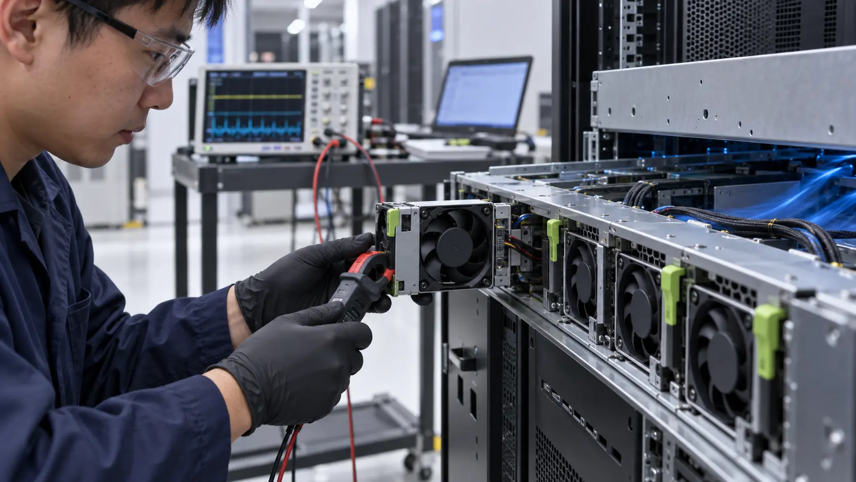
The normal dashboard showed acceptable current, but a high-speed oscilloscope trace revealed a short supply dip during fan insertion.
The integrator recorded supply voltage at the fan connector, tray current, individual fan current where possible, PWM command, FG frequency, RD state, inlet temperature, installed pressure and rack power. Tests were repeated with one fan, the complete tray and the neighboring fans already running.
The first candidate started correctly in isolation. In the populated tray, several simultaneous starts created a larger current pulse and a short feedback delay. The server controller interpreted the delayed tach signal as a fault even though the fan reached speed moments later.
The team separated three conditions: cold start from zero, PWM restart while the tray remained powered, and hot-swap insertion into a running tray. Each condition received its own acceptance record.
Interactive: Watch the Restart Pulse and Airflow Recover
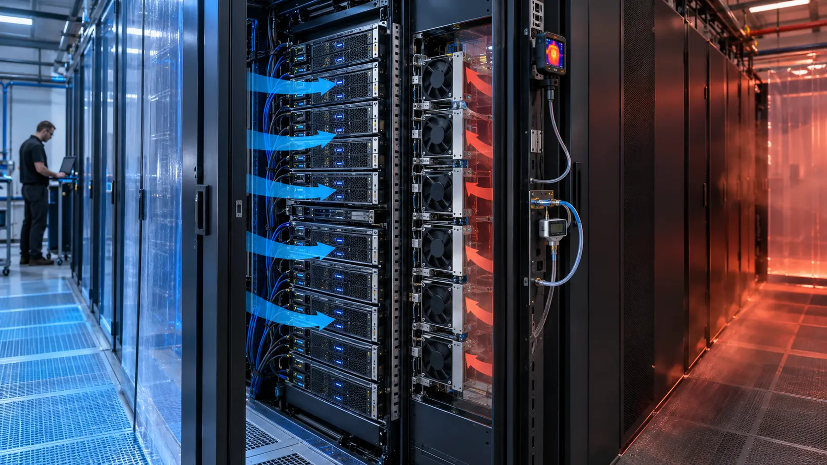
The animated schematic shows a fan insertion event, a temporary current pulse and the recovery of useful airflow.
The figure is qualitative, not a current waveform or a product timing specification. It shows why the controller's detection window must be long enough to distinguish a valid startup from a failed rotor, while still protecting the rack if the fan never reaches speed.
The test retained the same voltage, connector, PWM command, tray pressure and neighboring fan state. This kept the electrical and thermal comparison tied to the real installation.

Sample 01: Freeze Voltage, Connector and Startup Conditions
The first sample task was to define the electrical interface before comparing airflow.
The integrator supplied rated voltage, permitted voltage range, connector pinout, PWM logic, frequency, FG pulse convention, RD active state, current limit, hot-swap sequence and controller debounce. The fan was checked at the minimum declared voltage and at the warm operating condition.
For an illustrative power estimate, six fans drawing 1.5 A at 12 V consume 108 W while running. If their combined startup pulse reaches 2.5 A per fan for a short interval, the transient load is 180 W before wiring and controller losses. These are examples only; the actual fan waveform must be measured.
MEGA Tech used the interface requirements to adjust motor electronics, connector, lead wires, startup behavior and sample control curve before the thermal comparison.
Sample 02: Measure the Installed Pressure During Restart
The second sample checked whether an electrical restart also created a temporary airflow or reverse-flow problem.
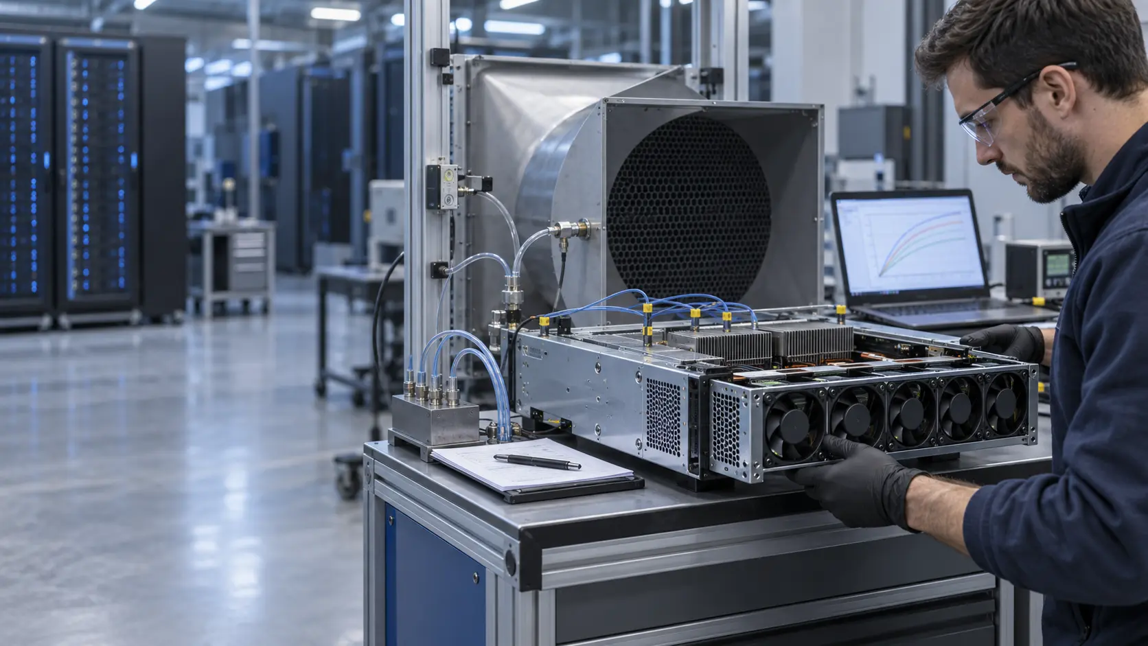
The tray was instrumented for pressure, inlet temperature, fan command, FG/RD and current. One fan was stopped, inserted or restarted while the remaining fans held their normal command. The test recorded time to first pulse, time to stable speed, pressure recovery and thermal response.
A fan that starts electrically but opens a low-resistance path can pull reverse flow through the tray or reduce the pressure available to neighboring paths. Conversely, a closed failed path can raise pressure on the remaining fans. The mechanical state and electrical state must therefore be recorded together.
The sample was accepted only when the restart sequence preserved the required airflow and did not produce an avoidable nuisance alarm or supply-voltage fault.
Sample 03: Validate Controller Debounce and Recovery
The final sample step made the controller distinguish a normal startup delay from a real fan failure.
The integrator defined a startup window, FG validation, RD behavior, PWM retry policy and thermal recovery action. The test used cold start, warm restart, fan insertion, fan removal and one failed-start condition. Exact timing remained specific to the server firmware and tray architecture.
The controller also checked whether all remaining fans could accelerate together without exceeding the tray supply or causing an acoustic spike. A retry that repeatedly restarts a stalled fan can be worse than a clear fault state, so the recovery logic was reviewed with the fan's protection behavior.
The customer retained responsibility for firmware, PSU protection, BMC/DCIM and complete server qualification. MEGA Tech supplied fan-side startup and installed operating data.
Validation Result: The Fan Sample Became a Reproducible Tray Component
The final package connected startup current, feedback timing, pressure recovery and thermal behavior into one release decision.
The record included voltage tolerance, connector, PWM and FG/RD timing, startup and restart current, installed P-Q points, inlet temperature, rack load, acoustic state, alarm delay and recovery time. It separated illustrative calculations from customer acceptance values.
The transferable lesson is that a fan replacement is not finished when the rotor spins and the steady-state CFM looks correct. The tray must survive the electrical events that service technicians and firmware will create during its life.
For procurement, request startup behavior, minimum operating voltage, feedback convention, restart timing, current limits and sample validation at the installed pressure. Same frame size and voltage do not prove hot-swap equivalence.
How MEGA Tech Supports AI Server Fan Tray Electrical and Thermal Validation
MEGA Tech helps server and rack integrators customize DC fans around the tray power path, control interface and installed airflow requirement.
We can review compact DC axial fans and blowers, startup and restart current, PWM and FG/RD signals, connector details, voltage tolerance, tray pressure, grille and heatsink losses, vibration, acoustic limits, bearing and life targets, and small first-build quantities. We can also evaluate alternatives to Sanyo Denki, SUNON, Delta, NMB, ebm-papst and other installed brands when the operating point is defined.
Please provide rack or chassis heat load, airflow and static pressure at that airflow, fan size, voltage tolerance, quantity, connector, PWM frequency, FG/RD convention, startup sequence, noise target, environment and life assumption.
Our scope is fan and air-path engineering, sample customization and comparative validation. We do not supply the customer's server firmware, PSU, BMC/DCIM, CRAH/CRAC, containment or facility safety design.
Engineer Questions About This Hot-Swap Case
Use these questions before approving a server fan tray or replacement fan with PWM and tach feedback.
Q: Is running current enough to size the fan power supply? A: No. Check startup, restart and locked-rotor behavior at the declared voltage and temperature.
Q: Can a valid PWM command guarantee a successful start? A: No. Practical mounting, pressure, voltage, minimum duty and controller timing can change the result.
Q: Why can a fan start alone but fail in a tray? A: Neighboring fans, shared supply impedance and simultaneous inrush change the electrical and aerodynamic conditions.
Q: Should the controller declare a fault immediately when FG is absent? A: Use a tested startup window and distinguish a normal delay from a failed start.
Q: What should I send for a review? A: Send heat load, airflow and pressure, fan size, voltage, quantity, control, connector, startup sequence, noise, environment and life target.
Q: Can MEGA Tech provide a custom sample? A: Yes. We can review the installed duty and support a sample comparison before production release.
Need an AI Server Fan Hot-Swap Review?
Send the rack heat load, installed airflow and static pressure, fan size, voltage tolerance, connector, PWM/FG/RD interface, startup sequence, noise target and service constraints. MEGA Tech will review the operating point before recommending a sample.
Include the current fan model, fan-tray photos, rack layout, workload profile, power-supply logs, alarm timing and any pressure or thermal measurements available. This helps separate a fan problem from a PSU, connector, firmware, tray or facility-airflow problem before the production BOM is locked.