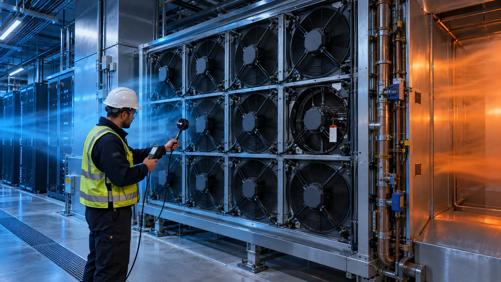
The Rack Passed Normal Operation Until One Fan Path Failed
An anonymized AI-infrastructure integrator needed to prove that a server fan tray could detect one fan fault, protect the rack and recover without turning every remaining fan into a permanent high-speed noise source.
The original tray had the expected signals on paper: PWM command, tachometer feedback and a fault output. In the installed rack, however, a stopped rotor, a disconnected feedback wire and a partially blocked air path did not create the same thermal event. The integrator wanted a replacement fan sample and a validation method that distinguished those cases before a production release.
MEGA Tech reviewed the fan electrical interface, tray geometry, pressure path, control logic, inlet temperature, server load profile and fault response. The objective was not simply to make an alarm appear. It was to show how much useful airflow remained after a fault, how quickly the control loop reacted, and whether the rack still had a defined thermal margin.
The customer identity and released acceptance values remain confidential. Values marked illustrative are engineering examples, not customer test results.
The Engineering Hook: FG and RD Do Not Prove Airflow by Themselves
A valid tachometer signal can coexist with a blocked outlet, an incorrect polarity or an operating point that has moved far left on the P-Q curve.
FG or tach feedback reports a rotational event. RD or locked-rotor output reports a motor or commutation condition. Neither signal directly measures the airflow reaching the server heatsink. A fan can rotate at the expected speed while a grille, filter, cable bundle or neighboring fan changes the pressure path.
This is why a fault validation plan needs at least four linked observations: command, feedback, installed differential pressure and a thermal response at the limiting component or inlet. The signal tells the controller what the fan reports; the pressure and temperature measurements tell the engineer what the rack receives.
ASHRAE data-center guidance describes fan selection, airflow management, fan-speed control, cooling zones, power and reliability as one thermal-management problem. In a dense AI rack, a single fan fault can therefore be an electrical, aerodynamic and control-system event at the same time.
The Problem in Operation: One Alarm Covered Three Different Failures
The rack controller reported a fan warning, but the first log did not identify whether the problem was a locked rotor, lost feedback or a pressure-path restriction.
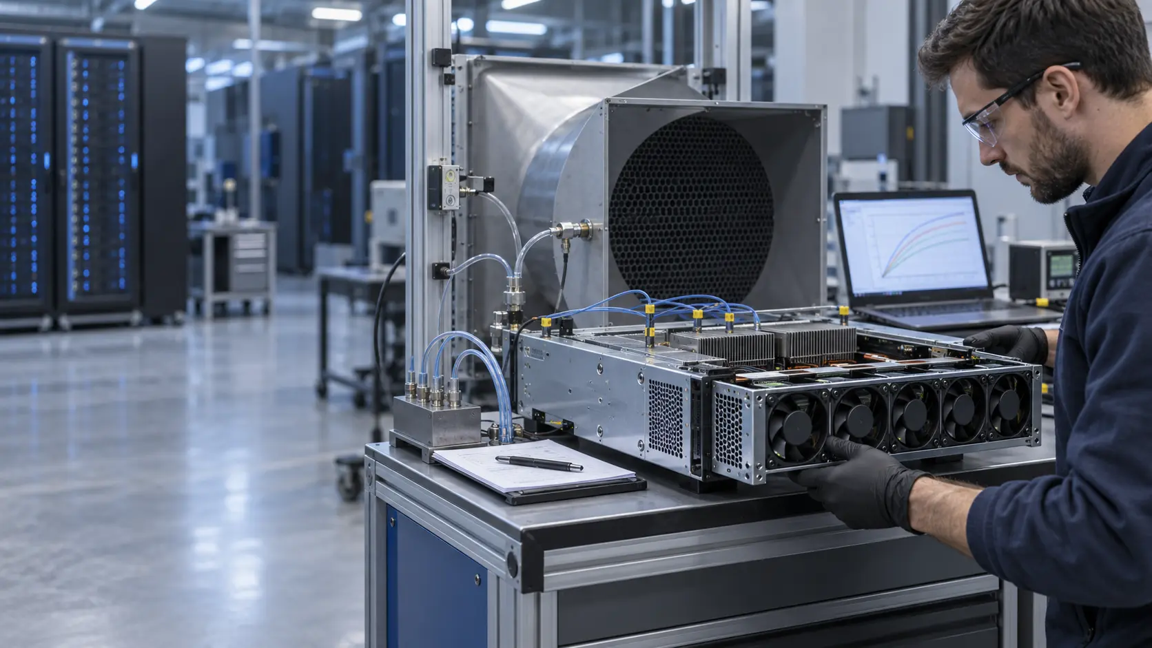
The integrator repeated the same compute workload while recording PWM command, supply voltage, current, RPM or FG frequency, RD state, inlet temperature, exhaust temperature, rack power and differential pressure across the tray. A pressure tap was placed close enough to the tray to represent the installed restriction, rather than relying on a free-air bench value.
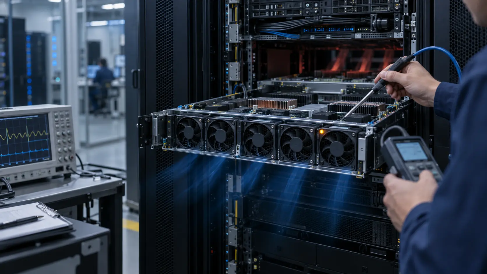
In the first state, one rotor was deliberately stopped. In the second, the fan continued to rotate but the feedback line was interrupted. In the third, the fan remained electrically healthy while the outlet path was restricted. These states can produce similar software symptoms but require different service actions.
A useful alarm record must therefore answer three questions: did the rotor move, did the controller receive the expected feedback, and did the remaining air path deliver enough cooling at the current rack load? The test was designed around those questions instead of around one generic fault bit.
Interactive: Watch N+1 Recovery Change the Airflow Path
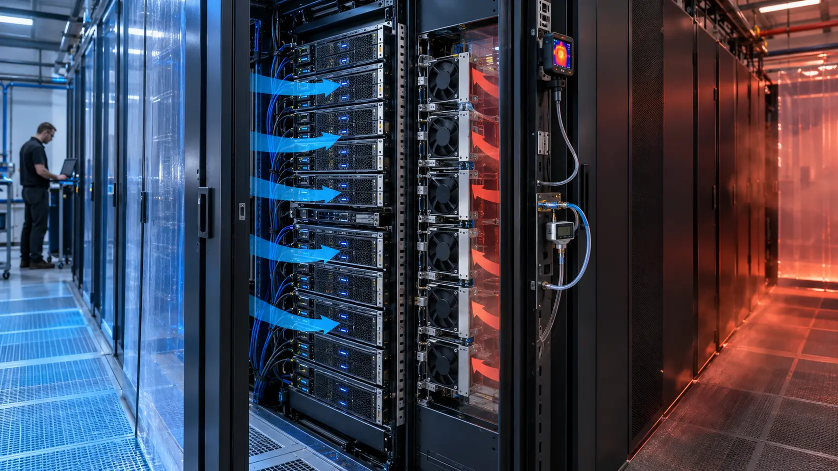
The animated schematic shows normal operation, one fan fault and the recovery state after the controller raises the remaining fan duty.
The figure is qualitative. It does not claim a universal N+1 airflow multiplier or a product performance value. Its purpose is to show why a failed fan changes the pressure and flow distribution across the remaining fan paths. If the failed unit is left open, the remaining fans may drive reverse flow through the idle path; if the geometry blocks that path, the tray pressure can rise while total airflow falls.
The recovery test used a defined time sequence: command the fault, capture the signal edge, record the remaining fan response, observe the rack inlet and component temperatures, then return to normal duty. The acceptance record kept the fault duration, rack power and containment state with the data so the result could be reproduced.

Sample 01: Freeze the Interface Before Changing the Fan
The first sample step was mechanical and electrical compatibility, not performance marketing.
The tray drawing recorded frame size, mounting hole pattern, connector keying, lead length, airflow direction, grille clearance and service access. The electrical sheet recorded nominal voltage, permitted tolerance, PWM logic level and frequency, FG pulse convention, RD active state, startup behavior, current limit and protection behavior.
A replacement that fits the opening but changes the feedback convention can create a false healthy state or a nuisance alarm. A replacement that starts reliably but draws a different inrush current can also trip the tray supply when several fans restart together. These details were frozen before the thermal comparison.
MEGA Tech can customize DC axial fans or compact blowers around the tray envelope, connector, control signals, bearing and life target. The sample is not accepted because the label looks similar; it is accepted after the interface and installed operating point are checked together.
Sample 02: Measure the Installed N+1 Operating Point
The relevant question was not whether the candidate fan could spin after one fault, but whether the rack still received useful airflow at its actual pressure.
For an illustrative estimate, assume a rack needs 0.75 m3/s at a 14 K air rise. At an assumed air density of 1.18 kg/m3 and specific heat of 1.005 kJ/(kg·K), the heat carried by the air is approximately 0.75 × 1.18 × 1.005 × 14 = 12.45 kW. This is a rack-level planning calculation, not a fan-tray result.
If a tray has six equal airflow paths and one is lost, a simple equal-share estimate might suggest 5/6 of the original flow, or 83%. Real installed flow can be lower because the open fault path creates reverse flow, the remaining fans move along a changed P-Q curve, and the server heatsink pressure is not uniform. The 83% value is therefore a screening estimate, not an acceptance claim.
The candidate sample was measured at normal duty and N+1 duty with the tray grille, cable path, blanking condition and server-side restriction in place. Pressure, airflow, fan command and thermal response were retained as one record.
Sample 03: Separate Fault Detection From Fault Recovery
A good fault strategy detects the event quickly, but it should not create an unstable speed loop or unnecessary acoustic penalty.
The control sequence used debounce and hysteresis so a noisy FG signal did not repeatedly declare and clear a fault. The test checked the delay from the physical event to RD or FG detection, the delay from detection to the recovery command, and the time for the limiting temperature to stop rising. Exact limits depend on the server and firmware and must be defined by the equipment owner.
The fan controller also checked minimum stable PWM, restart behavior, and whether all remaining fans could accelerate without an unacceptable supply-voltage dip. If the failed fan remains mechanically open, the control logic may need a damper, shutter, tray geometry or a different recovery speed. That is a system decision, not a universal fan rule.
Noise was logged during both normal and recovery duty. A short high-speed recovery may be acceptable; a fan array that remains at maximum speed after every transient may meet temperature limits while failing the acoustic and energy objectives of the data center.
Validation Result: The Fault Became a Reproducible Design State
The final sample package made fault behavior reviewable by thermal, electrical, firmware and procurement teams at the same time.
The release record included interface drawings, PWM and FG/RD timing, installed P-Q points, normal and N+1 airflow, pressure, current, inlet and component temperatures, alarm delay, recovery time, acoustic condition and the exact tray configuration. The record also stated which values were supplier measurements, which were customer acceptance limits and which were illustrative calculations.
The transferable lesson is simple: N+1 is not proven by counting fans. It is proven by defining the failed state, measuring the changed pressure path, and demonstrating that the remaining system protects the limiting load for the required time. Feedback signals make that state observable; they do not replace airflow and thermal validation.
For procurement, the same frame size and voltage are only the starting point. A viable alternative must preserve the installed duty, electrical interface, fault semantics, noise behavior, life assumption and sample-to-production consistency.
How MEGA Tech Supports AI Server Fan Fault Validation
MEGA Tech helps server and rack integrators turn a fan replacement or custom tray requirement into a measurable sample plan.
We can review compact DC axial fans and blowers, fan-tray pressure, grille and cable losses, PWM and FG/RD signals, connector details, startup and restart behavior, vibration, acoustic limits, bearing and life targets, and small first-build quantities. We can also evaluate alternatives to Sanyo Denki, SUNON, Delta, NMB, ebm-papst and other installed brands when the operating point and interface are defined.
Please provide rack or chassis heat load, airflow and static pressure at that airflow, temperature and altitude basis, fan size, voltage tolerance, quantity, PWM/FG/RD convention, connector, noise target, fault response, environment and life assumption. If data is incomplete, send the current fan part number, tray photos, rack layout, measured inlet temperatures and any pressure or alarm logs available.
Our scope is fan and air-path engineering, sample customization and comparative validation. We do not supply the customer's server firmware, DCIM/BMS, CRAH/CRAC, containment or facility safety design.
Engineer Questions About This Fault-Validation Case
Use these questions before approving a server fan tray, replacement fan or N+1 control curve.
Q: Does FG prove that the server is receiving airflow? A: No. FG proves a rotational signal. Confirm installed pressure, airflow and thermal response at the rack duty.
Q: Is RD enough to detect every cooling failure? A: No. A blocked grille, disconnected sensor, open reverse-flow path or wrong wiring can create a thermal problem without a locked rotor.
Q: Does five of six fans mean 5/6 of the airflow? A: Not necessarily. The pressure curve, reverse flow and tray geometry change after a fault.
Q: Should all remaining fans go to 100% immediately? A: Test the thermal response, pressure interaction, acoustic penalty and supply limit before defining the recovery command.
Q: What should I send for a review? A: Send heat load, airflow and pressure, fan size, voltage, quantity, control signals, connector, noise, fault behavior, environment and life target.
Q: Can MEGA Tech provide a custom sample? A: Yes. We can review the installed duty and support a sample comparison before production release.
Need an AI Server Fan Fault and N+1 Review?
Send the rack heat load, installed airflow and static pressure, fan size, voltage, PWM/FG/RD interface, fault sequence, noise target and containment constraints. MEGA Tech will review the operating point before recommending a sample.
Include the current fan model, fan-tray photos, rack layout, workload profile, inlet-temperature data, alarm logs and any pressure or acoustic measurements available. This helps separate a fan problem from a tray, sensor, control or facility-airflow problem before the production BOM is locked.