The Fan Question That Can Create a Safety Problem
A fan that keeps a battery cabinet within its normal temperature range is not automatically an emergency exhaust fan, and an emergency exhaust system is not a substitute for normal thermal management.
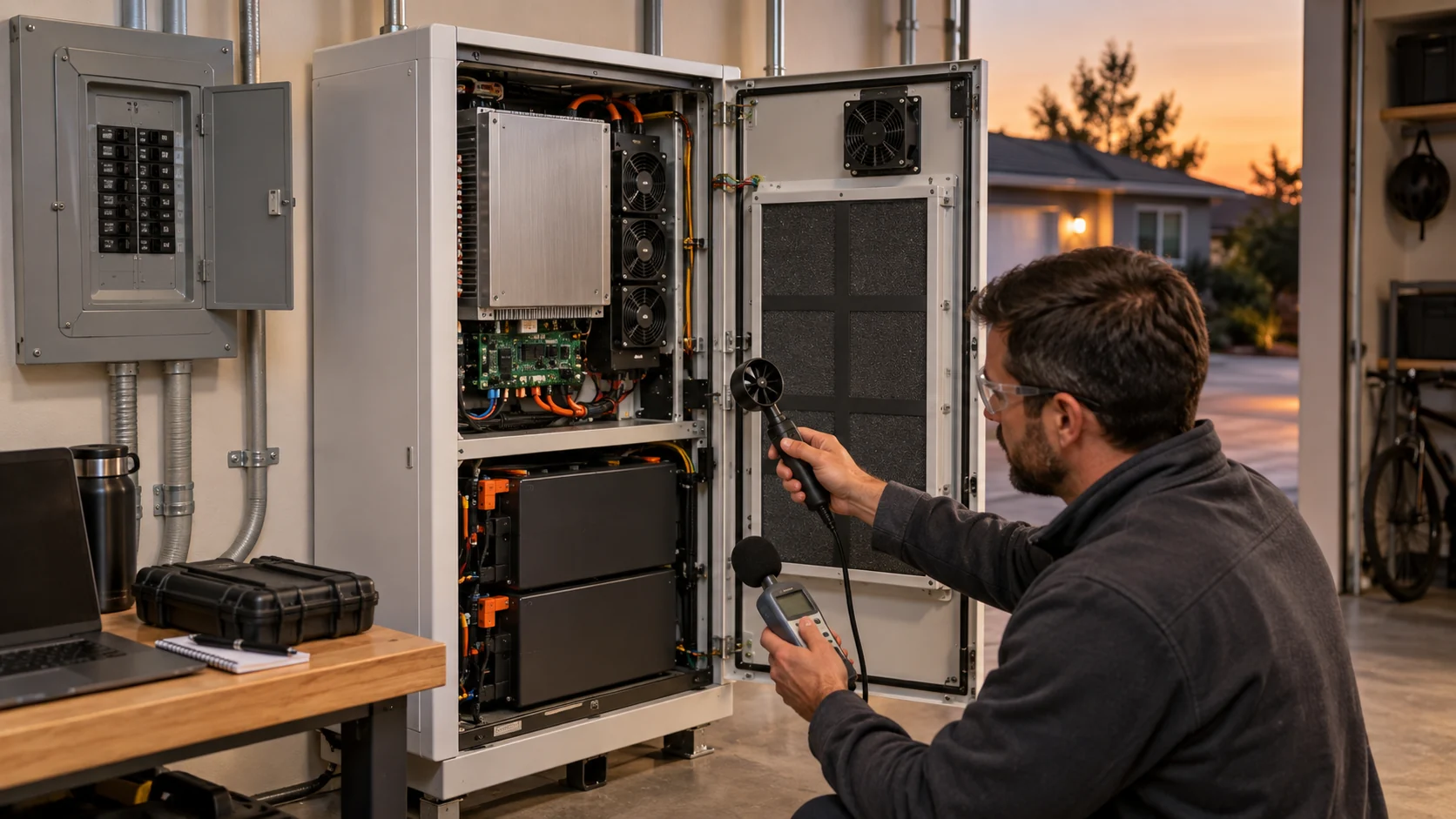
Battery energy storage projects often use the word ventilation for several different duties. A normal cooling path removes heat from cells, busbars, power electronics, contactors and auxiliary equipment during charging, discharging and standby. An HVAC or liquid-to-air heat exchanger may move air across a coil. An emergency system may be part of a gas detection, exhaust, deflagration-control or fire-protection strategy. These paths can share a cabinet, but they should not be collapsed into one undefined fan requirement.
The distinction matters because the design inputs are different. Normal cooling starts with heat load, allowable temperature rise, airflow distribution, pressure drop, noise and life. Emergency ventilation starts with the hazard analysis, detection logic, gas composition, relief strategy, classified equipment requirements, power availability and the authority having jurisdiction. A catalog fan's maximum CFM cannot prove either duty.
This guide gives a review method for the boundary. It does not certify an emergency ventilation design and it does not replace the applicable listing, fire-protection design or local approval. Its purpose is narrower and practical: make the normal cooling fan specification testable, identify where emergency functions begin, and stop a thermal fan quotation from being used as a safety claim.
Three Air-Movement Duties in One BESS Project
Name the duty before naming the fan. The same enclosure can contain three separate air-moving problems.
Duty A is normal thermal cooling. The air remains part of the ordinary operating envelope. A fan, blower or HVAC coil path is selected from an installed system curve and validated at the hot and cold operating limits. The acceptance question is whether every critical component stays within its limit while the battery charges, discharges, idles and follows a realistic power step.
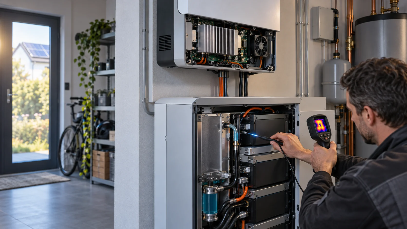
Duty B is heat rejection through a coil or heat exchanger. The fan does not cool the cells directly; it rejects heat from a liquid loop, refrigerant circuit or air-to-air core. Its pressure drop is set by coil face velocity, fin density, wet or dry condition, guards, filters and the discharge plenum. A fan selected from free-air flow can miss the coil duty even when the battery-side liquid loop is correctly sized.
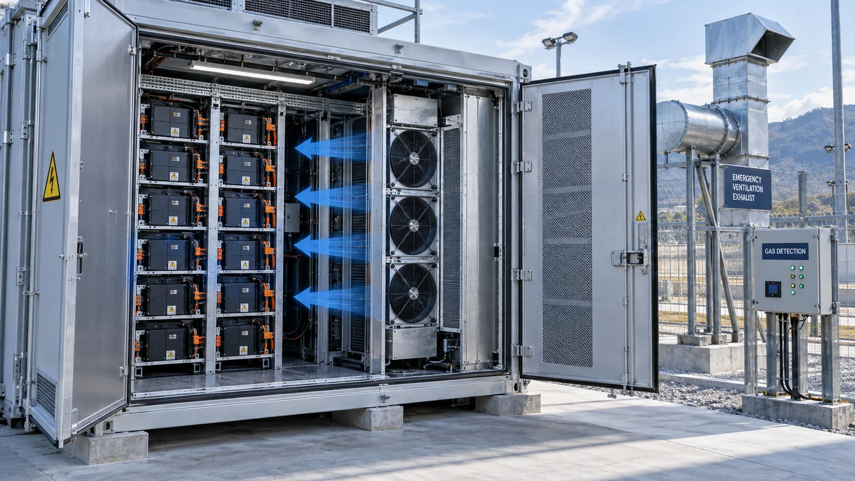
Duty C is abnormal or emergency ventilation. The airflow, start command, power source, construction and interlocks are determined by the safety design. The question may be gas concentration reduction, pressure relief interaction, smoke control or another project-defined function. The safety engineer must define the duty and acceptance criteria. Do not infer them from a normal cooling fan's airflow number.
| Duty | Primary design input | Evidence required |
|---|---|---|
| Normal thermal cooling | Heat load, allowable temperature, installed pressure-flow point | Thermal test at worst ambient, clean and loaded resistance, measured airflow and temperatures |
| Coil or heat-exchanger air side | Coil pressure drop, face velocity, air density, fouling state | Fan curve at the assembled coil, coil-side pressure and heat-rejection test |
| Emergency or abnormal ventilation | Hazard analysis, detection logic, gas or smoke strategy, local code | Approved safety design, listed equipment where required, interlock and failure-mode validation |
Normal Cooling Starts With Heat, Not Stored Energy
A 5 MWh battery does not tell you the fan airflow. The losses in the operating mode do.
For a first engineering estimate, sum the heat sources that actually enter the air path. Cell and busbar losses, DC contact resistance, converter losses, auxiliary power supplies, pumps, controls and solar gain all belong in the heat balance when they share the enclosure. Stored energy is a capacity number; it is not a cooling load. Power rating is also not identical to heat load, because a 100 kW converter may reject a fraction of its throughput as heat and that fraction changes with load and efficiency.
For sensible air cooling, use Q = P/(rho x cp x delta T). If 3,000 W enters an air path, air density is estimated at 1.10 kg/m3, cp at 1,005 J/kg-K and the allowed air temperature rise is 8 K, the first estimate is 3,000/(1.10 x 1,005 x 8) = 0.339 m3/s, or about 1,220 m3/h. This is a heat-balance estimate, not the fan selection. Add the system resistance, recirculation risk, altitude and service condition before choosing the operating point.
If the system rejects heat through liquid, the same logic moves to the coolant side: Q = P/(m-dot x cp x delta T). The air-side fan still needs its own heat-exchanger curve. A liquid-cooled battery rack may need a smaller internal air path than a fully air-cooled rack, but its power electronics, pump electronics, contactors and heat exchanger still create a real fan duty.
Animated Model: Normal Air, Liquid Heat and Emergency Exhaust Are Different Paths
The figure is a qualitative model for design reviews. Moving particles show the path distinction; they are not a CFD result or a safety calculation.
The blue path is the normal thermal duty: it has a heat load, a system curve and a fan operating point. The cyan path is a liquid-to-air interface: the fan removes heat from a coil, but it does not replace the pump, cold plate or liquid-control design. The red path is shown separately because its trigger, controls and equipment requirements come from the safety strategy rather than from the normal thermal setpoint.
This separation is useful during a design review. If a supplier is asked to quote one fan for all three paths, the project team should stop and list the operating states. Normal cooling may run continuously at variable speed. Emergency exhaust may require a specific start sequence, independent power, interlocked dampers, gas detection and equipment suitability defined by the approved design. Those are not safe assumptions to add after the fan has been purchased.

How to Select a Normal Cooling Fan Against the Installed Path
The correct fan is the one that delivers the required airflow at the assembled pressure, not the one with the largest free-air number.
Draw the path from inlet to outlet. Include louver, filter, guards, battery-module channels, heat sinks, coil or heat exchanger, duct transitions, cable obstructions and the discharge opening. Convert each item into a pressure-drop estimate or measurement at the target flow. The system curve normally rises approximately with Q squared, so doubling airflow can require roughly four times the pressure drop for the same geometry. The actual exponent changes with filters, dampers and flow regime; measure the path when the design is important.
Then overlay the fan P-Q curve at the real voltage, speed command and air density. Use at least two meaningful states: clean and service-loaded resistance. Add the high-ambient state if the fan or cabinet is near its temperature limit. A practical example is a clean path at 180 Pa and a loaded path at 290 Pa, both requiring 1,000 m3/h. If a fan only provides 1,000 m3/h at 180 Pa, it has not proven the loaded state. The fan needs a curve and control margin that reach the loaded point without running beyond its thermal or acoustic limit.
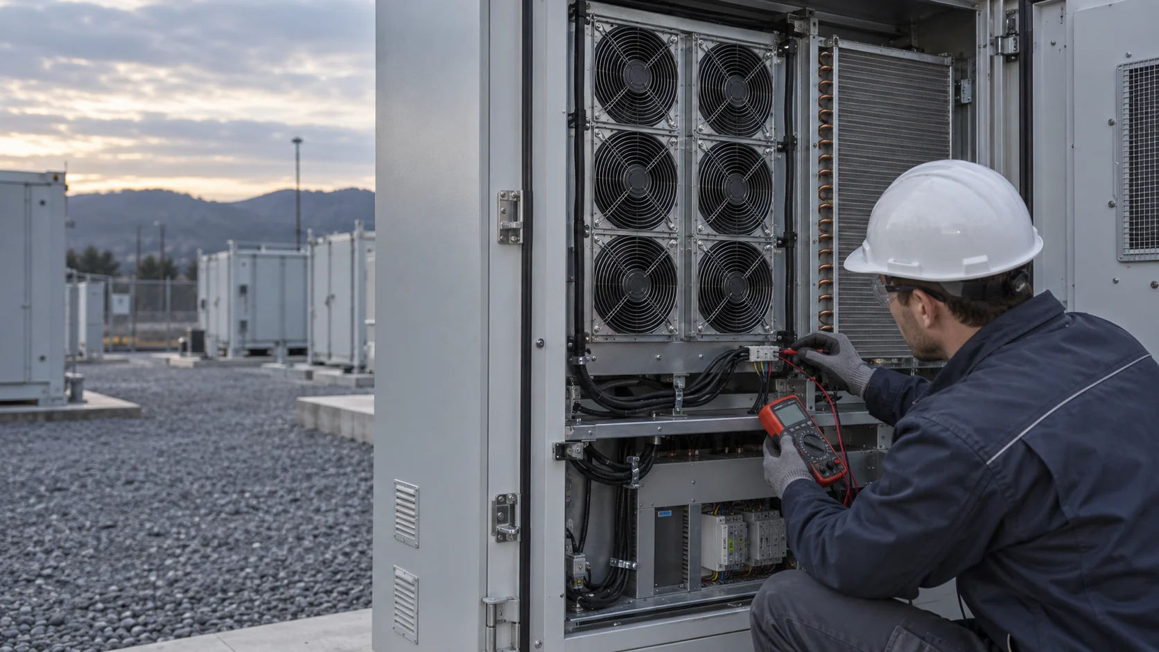
For a replacement or custom sample, record fan inlet pressure, outlet pressure, voltage, command, FG speed, current, component temperatures and the airflow measurement method. The same evidence should be repeated with the cabinet closed. An open-door test can hide bypass paths that disappear in the installed assembly.
Why a Normal Cooling Fan Cannot Be the Safety Strategy
Thermal management and hazard mitigation can interact, but they cannot be proven by the same datasheet line.
A normal cooling fan is usually selected for an operating envelope in which the enclosure, controls and air path are intact. During an abnormal event, the temperature, gas composition, pressure, power state and airflow direction may be different. A normal fan may stop because the controller trips, may be isolated by a damper, may be unsuitable for the atmosphere, or may create an airflow interaction that the safety design has not evaluated. The point is not that a normal fan is always forbidden; the point is that its role must be explicitly defined by the approved design.
NFPA 855 public committee material calls for failure-mode evaluation of critical systems including exhaust ventilation, cooling systems, BMS and communication systems. UL Solutions describes UL 9540A as an installation-level method for evaluating thermal runaway and fire behavior, including realistic fire and deflagration conditions. Those sources support a disciplined boundary: the safety function requires its own hazard analysis and test evidence; it should not be inferred from a fan vendor's normal cooling curve.
For the article reader, the procurement consequence is simple. Ask the safety designer which components are in the emergency path, which states they must survive, what approval or listing is required, and what the acceptance test is. Ask the normal cooling fan supplier for the operating-point evidence of the normal path. Keep both evidence packages linked but separate.
Controls: Normal Thermal Feedback and Emergency Interlocks
A temperature loop and a safety interlock may share sensors, but they should not share undocumented assumptions.
Normal cooling control can use inlet temperature, outlet temperature, cell temperature, heat-sink temperature, pressure difference, PWM command and FG feedback. The controller should define minimum speed, startup behavior, locked-rotor response, fan-loss detection and the action when the filter pressure is high. A fan at 2,400 RPM with low delivered airflow may be a restriction problem, not a healthy operating point.
Emergency logic is different. The safety system may require independent detection, alarm escalation, isolation, shutdown, damper sequencing or an approved exhaust response. If normal thermal control is allowed to participate, the interface and failure state must be documented. A design that says the BMS will run the fans faster during an abnormal event is incomplete until power, command priority, feedback validity and failure response are tested.
For a first sample, create a state table rather than a single speed command. Record normal idle, charge, discharge, high ambient, loaded filter, fan failure, sensor fault and any abnormal state defined by the safety team. Mark which controller owns each state and which signal proves the transition happened.
| State | Record | Pass criterion |
|---|---|---|
| Standby or low load | Command, FG, current, inlet and outlet temperature | No hunting; minimum speed maintains defined component margin |
| Rated charge/discharge | Airflow, static pressure, heat-sink and cell temperatures | All critical temperatures remain below the design limit at the installed point |
| High ambient | Ambient, intake, fan temperature and available speed | Required airflow remains available without exceeding fan limits |
| Loaded filter | Filter differential pressure and delivered airflow | Airflow and thermal margin remain valid until the defined service threshold |
| Fan or sensor fault | Alarm latency, fallback command and thermal response | The documented safe response occurs and the operator receives a clear alarm |
Air Density, Fan Temperature and Life Are Part of the Same Duty
A normal operating point can move when the air is hot, thin or contaminated, and the fan itself must survive the same environment as the cabinet.
Airflow volume and mass flow are not interchangeable at every site. For a first estimate, air density at 50 degrees C and sea level is about 1.09 kg/m3, while at a high-altitude site it is lower again. The fan may still display the same volumetric flow, but the mass flow and the heat carried per unit volume change. When the heat balance is tight, state the ambient temperature, altitude and density basis in the requirement rather than leaving the supplier to assume standard air.
High ambient also changes the fan's own thermal condition. Motor winding temperature, electronics temperature, bearing grease and magnet temperature can all be closer to their limits while the cabinet is asking for more speed. A fan that reaches the required airflow at 35 degrees C is not automatically qualified at 50 or 60 degrees C. The sample plan should record fan inlet temperature, command, current, RPM and the hottest accessible fan or motor surface while the cabinet operates at the design duty.
Life must be expressed against the real duty cycle. If the fan runs at high speed only during a short charge peak, the control profile may reduce acoustic and bearing stress. If it runs continuously in a dusty or salty stream, filter maintenance and construction may dominate life. Ask for the life assumption, reference temperature, speed profile and environmental boundary. Do not convert a catalog L10 number into a guaranteed cabinet life without matching those conditions.
These details also help procurement compare alternatives fairly. A lower-cost replacement may be technically attractive if it reaches the same installed point, but the comparison must include control compatibility, temperature margin, environmental construction, service interval and the evidence required by the design review. Outline dimensions alone are not equivalence.
Altitude can be handled in the first calculation without pretending that the result is a final test. At a high site, calculate the mass-flow requirement from the local density, then check the fan curve and motor temperature at that density and ambient. If the cabinet uses a pressure sensor, confirm that the sensor location does not confuse outdoor barometric pressure with the differential pressure across the air path. A small instrumentation error can look like a fan margin problem.
The same discipline applies to the maintenance record. Save the filter differential pressure, fan command, FG speed, current and representative component temperature together. A six-month trend showing increasing pressure at the same command is more useful than a one-time RPM snapshot. It tells the service team when the normal cooling path is approaching its boundary, before a high-temperature alarm becomes the first evidence. Add the date, ambient condition and filter state to each record so a later engineer can distinguish seasonal density changes from real fouling.
A Practical Hybrid BESS Example
The useful result is not a bigger fan; it is a clear division of responsibility and a measurable acceptance plan.
Consider an anonymized outdoor cabinet with a liquid-cooled battery rack and an air-cooled power-electronics bay. The battery loop carries most cell heat to a remote heat exchanger. The cabinet still contains contactors, control electronics, auxiliary supplies and a liquid-to-air coil. The first design used one generic fan command for the coil and the electronics bay. At high ambient, the power electronics stayed acceptable, but the coil-side pressure increased as the filter loaded and the liquid return temperature rose.
The engineering response was to separate the air paths, measure each pressure drop, and define two normal cooling states: a lower-speed electronics path during light load and a higher-pressure coil path during rated operation. The supplier sample was evaluated at clean and loaded filter conditions, with the enclosure closed and the final louver installed. The result was not expressed as a universal percentage improvement; it was recorded as an operating-point table showing airflow, pressure, current, RPM and component temperature in each state.
The safety review remained separate. The project team documented that normal cooling fans were not the emergency exhaust strategy and routed the emergency question to the approved hazard-mitigation design. That boundary prevented a thermal sample from being treated as a safety certification while still allowing the fan supplier to solve the normal heat-rejection problem.
What MEGA Tech Can and Cannot Provide
We help turn the normal thermal duty into a fan sample and a testable specification, while keeping safety-system responsibilities visible.
We can provide custom DC axial fans, compact blowers and backward-curved centrifugal fans selected for the installed operating point. We can review the pressure-flow requirement behind your filter, louver, heat sink or coil; match voltage and control interfaces such as PWM, FG and RD; adapt the mechanical envelope, connector and mounting; and support samples that are tested in the customer's cabinet or representative air path. We can also evaluate replacement options by operating condition rather than by outline dimensions alone.
To begin, send the normal cooling heat load, required airflow and static pressure at that airflow, clean and loaded filter conditions, ambient and altitude basis, voltage tolerance, PWM frequency or analog command, FG/RD behavior, connector, space, noise target, environmental exposure, quantity and life assumption. If a coil is involved, include its pressure-drop curve and face area. If an emergency path exists, identify it separately and state which requirements belong to the safety integrator.
We do not supply the BESS safety case, fire-protection strategy, gas detection logic, deflagration-relief design, emergency ventilation certification, liquid loop, cold plate, cabinet or controller unless a separate verified scope says otherwise. Our role is to make the normal fan duty concrete, selectable and sample-testable, and to provide the evidence needed for the thermal design review.
Engineer FAQ: BESS Cooling and Emergency Ventilation
These questions keep a fan quotation, a thermal test and a safety review from being mixed together.
Q: Can the same fan serve normal cooling and emergency exhaust? A: Sometimes a project may define shared hardware, but that is a safety-system decision. The fan, power, controls, atmosphere, dampers and failure modes must be evaluated for both duties. Do not assume it from the normal P-Q curve.
Q: Does a higher CFM fan improve thermal-runaway safety? A: Not automatically. Emergency ventilation depends on the approved hazard analysis, detection, gas behavior, pressure relief and equipment suitability. A normal cooling fan's free-air CFM is not safety evidence.
Q: Why does a liquid-cooled BESS still need fans? A: Auxiliary supplies, controls, contactors, pumps, power electronics and the liquid-to-air heat exchanger may still need forced air. The liquid loop removes only the heat that reaches it.
Q: What pressure should I give the fan supplier? A: Give airflow and static pressure at the installed operating point, including louver, filter, guard, coil, heat sink and discharge. Provide clean and service-loaded states when the filter is part of the path.
Q: Is a fan alarm enough to prove the cooling path is healthy? A: No. Combine command, FG, current, pressure difference, airflow or temperature evidence. Normal RPM can coexist with a restricted path and reduced delivered airflow.
Q: What should the sample acceptance test include? A: Test the fan in the representative path with the enclosure closed. Record voltage, command, RPM, current, pressure, airflow, ambient, component temperatures and fault behavior across the defined operating states.
Questions for a Design Review
Use these questions before freezing the BESS fan specification or treating it as a safety requirement.
- Which airflow duty is being specified: normal cooling, coil heat rejection or emergency ventilation?
- What heat load and allowable temperature rise produce the first airflow estimate, and which losses are included?
- Where is the measured or calculated system curve, including clean and loaded filter states?
- Does the fan curve reach the required operating point at high ambient and the actual air density?
- Which sensors prove delivered airflow or thermal performance rather than only fan RPM?
- Which safety document defines abnormal ventilation, detection, interlocks, power and failure response?
- Are the normal fan quotation and the emergency ventilation evidence kept as separate approval packages?
- What exact information will be sent to the supplier for a sample: airflow, pressure, voltage, control, envelope, environment, noise, quantity and life?