A Heat Exchanger Fan Is Selected at the Coil, Not on the Datasheet
The useful airflow number for a liquid-to-air heat exchanger is the airflow the fan can still deliver once the louver, the filter, the coil and the discharge path are in front of it. That is the installed operating point, and it is almost never the free-air figure at the end of the curve.
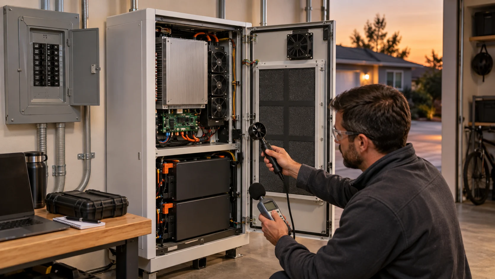
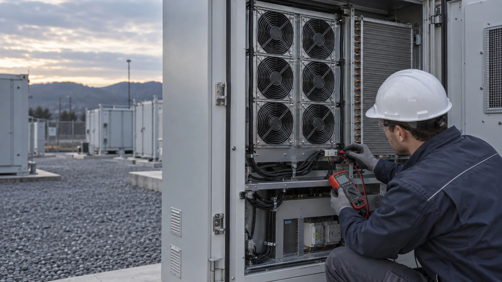
A BESS liquid-to-air heat exchanger puts a chain of restrictions between the fan and the outside air: a weather louver or guard, a filter, the coil face, the transition into the duct and the discharge path. Each element consumes pressure. The fan can operate only where its curve crosses the system curve, so a fan that looks generous at zero pressure can deliver a very different airflow once the real air path is assembled. Reading the fan P-Q curve properly is the prerequisite skill here, not an optional extra.
The gap is not a rounding error. On a heat-exchanger air path the coil and the filter usually dominate the system resistance, and a small axial fan can lose a large part of its free-air rating once it has to work against them. The figure further down this page shows the same fan on an open test stand and behind the installed air path. Both numbers are true. Only one of them describes the cabinet.
Three conditions decide the result and all three have to be stated together: the airflow the coil needs, the pressure the installed path produces at that airflow, and the air density the fan will actually see. A selection made without one of the three is a guess with a datasheet attached to it.
This article covers normal cooling duty: rejecting heat from the liquid loop, or from the cabinet air, under the conditions the project permits. Project-defined abnormal or emergency ventilation is a separate function with separate hardware, separate control logic and a separate approval basis. A normal cooling fan is not evidence for that duty, and it should never be presented as one.
Build the Coil-Side Pressure Budget Before Choosing a Fan
Add the restrictions at the target airflow, then compare candidate curves at the same voltage, speed and air density the equipment will actually use.
There is no universal BESS pressure-drop number, and there is no rule that a particular pressure always calls for a particular fan type. A shallow coil, a fine filter, a long discharge duct and a weather louver can change the result materially. Take supplier data where it exists, then confirm the assembled path with a representative measurement of your own rather than a sum of catalogue values.
Filter data is the easiest part of the budget to pin down, because the industry publishes replacement triggers. For ISO 16890 filters a common final-resistance criterion is the initial pressure drop plus 100 Pa, or three times the initial drop, whichever is reached first. Under the older EN 779 classes the quoted final resistances run from about 150 Pa for G1 to G4 and about 200 Pa for M5 to M6 and F7. Those figures are maintenance triggers rather than design points, but they show the order of magnitude a single filter can add between a clean cabinet and one that is due for service.
For an early heat-balance screen the air-side arithmetic is simple. In the units most fan curves are published in, CFM is approximately watts divided by 1.76 times the permitted air temperature rise in degrees Celsius. A 3,000 W duty with a 12 C rise therefore needs about 142 CFM of air. That estimate only opens the conversation: the coil, filter and enclosure curve decide whether the proposed fan can deliver it, and for the first fan most projects propose, the answer is often no.
Record each element with the condition it is in, not just its name. A pressure budget written as a single number is unusable six months later, because nobody can tell which maintenance state it described.
| Air-path element | What changes its loss | Evidence to retain |
|---|---|---|
| Louver, guard and intake | Free area, rain geometry, icing or debris | Supplier curve or installed differential pressure |
| Filter | Media, face velocity, clean and loaded state | Clean baseline and a defined service state |
| Liquid-to-air coil | Fin geometry, face velocity and fouling | Coil air-side pressure data at the target flow |
| Transition and duct | Abrupt area change, bends and leakage | Drawing plus a representative measurement |
| Discharge path | Backdraft damper, grille and cabinet recirculation | Installed observation and temperature check |
| Cabinet return path | Bypass around the coil and short-circuit airflow | Airflow and temperature map at the coil face |
Read the Candidate Curve at the Real Operating Conditions
A fan curve is drawn for one speed, one voltage and one air density. Every one of those changes in service.
The fan laws relate the three quantities that matter. Flow changes in proportion to speed, pressure rises with the square of speed and shaft power rises with the cube. Recovering airflow by raising speed is therefore the most expensive option available: a 20 % speed increase asks for roughly 70 % more power and raises the acoustic output with it. It also assumes the fan still has the pressure headroom to reach the higher speed against the system resistance, which is exactly the headroom a loaded filter has already removed. Changing between series and parallel arrangements changes which lever is available, but not the arithmetic.
Air density matters as much as speed and is left out of most enquiries. A fan is a constant-volume machine, so the mass of air it moves falls with density while the volumetric reading stays roughly the same. At 45 C air carries about 8 % less mass than at 20 C at the same pressure, and a site at 2,000 m altitude loses roughly 21 % against sea level. The coil still sees the same volumetric airflow, so the temperature rise across it is larger than the mild-day calculation predicted. The fan looks adequate on paper and runs out of margin on the hottest afternoon of the year, which is the afternoon the acceptance test should have been written for.
Installed conditions subtract airflow in ways the free-air curve cannot show. AMCA groups them under the system effect: obstructions close to the fan, poor inlet and outlet geometry and an uneven approach all cost airflow without appearing anywhere in the catalogue. A finger guard, a bend immediately downstream, or a coil mounted hard against the fan discharge are three common versions of the same loss.
Put all of it into the fan enquiry as stated conditions: speed or command, supply voltage and its tolerance, air temperature and either altitude or density, and the pressure required at the target airflow. A supplier who is given those can be held to a number. A supplier who is given only a free-air figure cannot, because nothing in the request defines what the fan has to achieve.

Interactive: Watch Filter Loading Move the Duty
Switch between maintenance states to see why fan RPM alone cannot prove coil airflow.
The model is qualitative. It is not a CFD result and not a performance curve. Its value is that it names the three states a test plan has to cover: clean reference, loaded filter and reduced fan mode. For each state, retain the exact filter condition, the command, the measured differential pressure, the fan feedback and the supply and return air temperatures together. Any one of those signals alone will mislead you about the other four.
Coil Face Velocity Sets Both Heat Transfer and Carryover
Airflow is not free to grow: the coil face area is fixed by the cabinet, so pushing more air through it means pushing that air faster.
Face velocity is the airflow divided by the free area the air actually sees at the coil. Because the coil is already inside the cabinet, raising the fan speed raises face velocity almost linearly. Air-side pressure drop rises roughly with the square of face velocity, so extra airflow is paid for twice: once in fan power and again in coil resistance. The casing and coil geometry, not the fan, is the highest-leverage decision in the whole air path.
Long-standing air-handling design guidance puts a ceiling on that velocity, and the ceiling exists because of water rather than efficiency. The classic figure for a cooling coil is a maximum of 500 fpm, about 2.5 m/s, with smooth fins and 550 fpm, about 2.75 m/s, with corrugated fins, against a practical lower bound of roughly 400 to 450 fpm, or 2.0 to 2.25 m/s, at design conditions. Published selection guidance for complete air-handling units uses comparable bands and states the reason directly: above roughly 2.8 m/s on a dehumidifying coil, moisture carry-over becomes a real design risk.
Condensate that forms on the fins has to leave the coil surface and reach the drain pan. Above a certain velocity the airstream re-entrains the droplets and carries them downstream, into the duct and towards whatever electrical equipment sits behind the coil. The consequence is not a small loss of capacity. It is water arriving where water must not be, and it arrives on the electrical side of the machine.
For a BESS this matters twice over. A liquid-cooled battery compartment rejects heat through a coil that is colder than the cabinet air, so the coil surface sits below the dew point whenever that air is humid, and the compartment contains high-voltage DC equipment designed for dry conditions. Dew-point control is a separate problem with its own sensing and its own control loop, and the moisture limits are written in dew point is where that discussion belongs. The point for this article is that the fan selection has already decided part of the answer: a coil chosen with a small face and a large airflow will carry water, no matter how good the control loop is.
| Component | Typical design band | Why the limit exists |
|---|---|---|
| Filter bank | 1.8 - 2.2 m/s, upper limit near 2.5 m/s | Loaded filters clog faster and cost more fan energy at high face velocity |
| Cooling coil, dehumidifying | 2.0 - 2.5 m/s, carry-over risk above about 2.8 m/s | Condensate has to reach the drain pan instead of the downstream duct |
| Cooling coil, sensible only | Higher face velocities are normally acceptable | No condensate forms, so pressure drop and noise set the limit |
| Coil section air path | Keep transitions gradual | An abrupt area change adds pressure loss and produces uneven flow across the face |
The Air Side and the Liquid Side Are Coupled by Approach Temperature
How hard the air side has to work is decided by how cold the liquid is, so the coolant temperature belongs in the fan specification.
Heat crosses the exchanger because a temperature difference exists. The coil surface sits close to the liquid temperature and the air leaves a few kelvin above it. The closer the coolant supply is to the air being cooled, the more airflow is needed to move the same number of watts, and the larger the coil has to be for the same pressure drop. A fan cannot be matched to a coil without knowing both temperatures.
Datacom liquid cooling formalises this as facility classes W1 to W5, defined by supply water temperature. The pattern is worth reading even for a battery storage project: pushing the coolant temperature up buys free-cooling hours and removes compressor energy, and it is paid for on the air side with a larger coil, more airflow or more fan power.
A battery energy storage system meets the same trade-off inside its thermal management unit. In free-cooling mode the liquid loop is cooled directly by ambient air and the compressor stops, which is where most of the annual energy saving comes from. The approach to ambient narrows at the same time, so the air-side flow and the fan power climb even as the refrigerant circuit idles. A fan selected only for the chiller-mode condition will be undersized for the mode that runs for most of the year.
Write the liquid side into the enquiry alongside the air side: coolant supply and return temperature at each design point, coolant type and glycol concentration, liquid flow rate and pressure drop, the air-side duty in watts, and the ambient condition that pairs with each operating mode. Without the coolant temperature the fan cannot be matched to a coil, only to an expectation.
| Class | Facility supply water temperature | Consequence for the air side |
|---|---|---|
| W1 | 2 to 17 C | Cold liquid, small air-side duty, chiller running year round |
| W2 | 2 to 27 C | Wider free-cooling window, air-side duty starts to grow |
| W3 | 2 to 32 C | Cooling tower carries the load; the coil approach narrows |
| W4 | 2 to 45 C | Essentially dry-cooler operation; the air side carries most of the rejection duty |
| W5 | above 45 C | Heat reuse territory; the air side is the whole rejection path |
Specify the Control Interface, Not Only the Fan
Half of a heat-exchanger fan specification is aerodynamic. The other half is electrical and logical, and it is the half that fails at commissioning.
A BESS thermal management unit usually exposes its fans through the unit controller rather than to the site directly. Published liquid-cooling units for battery cabinets describe DC speed-controlled fans and pumps with Modbus-RS485 or CAN to the battery or energy management system. That architecture is sensible, and it means the fan interface has to be verified against the controller's real register map and hardware rather than against a protocol name on a datasheet.
The list below is the interface content a fan quotation should be able to answer. Anything left blank becomes a commissioning risk that shows up as a fan that runs at the wrong speed, reports the wrong status, or does not come back after a supply dip.
- Supply voltage and the permitted variation, and whether the fan shares a rail with the pump and the controller
- Command method: PWM, 0-10 V or a network register, with the frequency, polarity and range the fan actually expects
- Feedback: FG or tacho output, and what the controller does when feedback and command disagree
- Alarm and status: what the RD line reports, whether it is open-collector or pulled up, and which conditions set it
- Starting behaviour: inrush current, the response to a blocked rotor, and whether the fan restarts by itself after a supply dip
- Connector, harness length and pinout, and which side supplies the mating half
- Loss of command: the state the fan holds, and whether that state is safe for the coil
Outdoor Heat Exchangers: Weather, Corrosion and the Free-Cooling Mode
If the air side draws outside air, the fan is an outdoor component whether or not the bill of materials describes it that way.
Weather sets the intake geometry. A louver that sheds rain in July can hold snow and ice in February, and a fan that is a balanced rotating mass in summer can become an unbalanced one when ice forms on a blade. The intake has to be checked against the worst month at the site, not against an annual average.
Dust, salt and pollution set the protection level. A coastal, agricultural or industrial site changes both the corrosion protection required and the rate at which the coil and the filter foul. The relevant evidence is the coating and material specification of the exact proposed fan model, not the product family name it belongs to.
Ingress protection is two separate ratings that are frequently confused. A fan rated for dust and water spray does not make the cabinet weatherproof, and a weatherproof cabinet does not protect a fan mounted in the outside air stream. Both have to be specified for the position the component actually occupies.
The free-cooling mode is the one that decides the acoustic and power envelope. As ambient falls, the air-side flow often rises even though the compressor has stopped, so the loudest and highest-power fan condition is frequently not the hottest day. Acoustic and electrical behaviour have to be checked across the operating modes, and the night-time limit is usually the binding one because BESS sites are often sited near where people live.
Use the Data the Unit Already Produces
The air side of a heat exchanger is the cheapest part of a BESS to instrument and the easiest part to ignore.
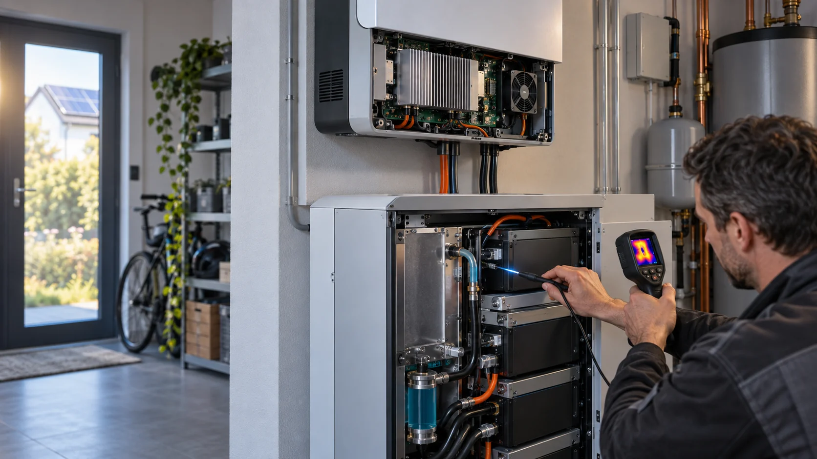
A unit with a filter and a fan already produces the signals needed to notice a change: differential pressure across the filter, fan command against fan feedback, and the air and liquid temperatures on each side of the coil. Trending them together separates a blocked filter from a slow fan from a fouled coil, which are three faults that look identical when only one signal is watched.
Set the service trigger from a measured baseline rather than from a calendar. A differential-pressure alarm referenced to the clean reading responds to the actual dust load, which matters on a site where a spring dust season and a quiet winter cannot share one maintenance interval. Filter differential pressure alarm covers the trigger logic and how to set it.
Remember what the fan can and cannot report. A fan that returns the commanded speed while the coil face is starved is faithfully reporting the only quantity it can measure. Keeping a coil approach temperature in the same trend is what turns a speed reading into a statement about airflow, and fan speed is not airflow is the mistake that this habit prevents.
What MEGA Tech Can Do for a Heat Exchanger Fan Project
The fan is one component with one specification. It either matches the installed duty or it does not, and the difference is measurable.
MEGA Tech designs and manufactures custom DC and EC cooling fans, including axial fans and backward-curved centrifugal blowers where the coil-side pressure is high enough that an axial fan has run out of usable headroom. We work from a duty rather than from a part number, which is the direct counter to the selection error this article describes: the fan is quoted at the airflow and pressure the installed air path actually produces, not at the free-air end of its curve.
What we need in order to quote against a stated operating point: the required airflow and the static pressure at that airflow; the air temperature and altitude basis; the supply voltage and its tolerance; the command, feedback and alarm interface; the connector and harness arrangement; the available space and mounting pattern; the noise target and where it is measured; the expected environment; and the life expectation with the assumptions behind it. That is the same list a design review needs, which is why the closing section of this article is built from it.
What a development sample can include: the fan matched to the airflow-pressure duty; the electrical interface verified against the customer's controller instead of assumed; a stated L10 life with its assumptions made explicit; the corrosion and ingress treatment agreed for the site; and a validation plan run in the customer's representative assembly, at the stated thermal load, with the filter in the state the project permits.
Where a project already carries a reference part from a premium brand, we can assess it and develop a candidate for the same installed duty at a lower cost. The condition is that the comparison is made at the same pressure, the same speed and the same density basis. A matching frame size is not a matching fan, and we will not describe a candidate as equivalent on external dimensions alone. The replacement validation workflow is what makes that comparison defensible.
What we do not supply: the coil, the liquid loop, the unit controller, the cabinet safety design or the emergency ventilation function. Those belong to the equipment and system supplier. Our scope is the air-moving component inside normal cooling duty, and stating that boundary plainly is part of giving a quotation that can be used.
Recommended Fan Starting Points
These catalogue series may be suitable starting points for this application. Final selection depends on the installed airflow, static pressure, voltage, noise target and operating environment.
Request a sample for validation on your equipment.
Engineer FAQ: BESS Liquid-to-Air Heat Exchanger Fans
These are the questions that turn a cooling enquiry into a fan requirement that can be tested.
Q: Is the free-air CFM rating enough to select a BESS heat-exchanger fan? A: No. Use the flow-pressure operating point of the assembled louver, filter, coil, transition and discharge path, then verify it in the representative assembly. The free-air figure is a starting reference, not a selection result.
Q: Does a liquid-cooled BESS still need air-side fans? A: Usually yes. The liquid loop has to reject its heat somewhere, and in most architectures that final step is a liquid-to-air exchanger with its own fans. Power conversion and auxiliary compartments may run separate air paths with their own fans. The architecture decides how many fan duties exist, and each one needs its own operating point.
Q: Can a higher RPM solve a loaded-filter problem? A: It may recover some flow if the fan curve and the power limit allow it, but the fan laws make that expensive: pressure rises with the square of speed and power with the cube, and noise rises with it. Measure the differential pressure and the thermal response. A speed command is not evidence of airflow.
Q: Should the fan be selected on the clean or the loaded filter? A: Size for the loaded condition the project permits and check that the clean condition still lands in a stable, controllable part of the fan curve. Selecting only on the clean filter produces a system that cannot hold its temperatures the week before servicing. Selecting only on a hypothetical fully blocked filter produces a fan that is oversized and noisy for the other 51 weeks.
Q: How does altitude change the fan selection? A: The fan moves the same volume of air but less mass, so the heat it can carry away falls. At 2,000 m the mass flow is roughly 21 % below sea level at the same pressure. Quote the fan at the site altitude rather than at sea level, and check the motor's cooling and the electronics' thermal margin as well.
Q: What is the difference between the fan's IP rating and the cabinet's? A: They describe different components. The fan's rating covers the fan in its own installed position; the cabinet's rating covers the enclosure. A well-rated fan does not make a cabinet weatherproof, and a weatherproof cabinet does not protect a fan sitting in the outside air stream.
Q: What information is needed for a custom fan sample? A: The heat load and the resulting airflow requirement, the coil and filter data, the enclosure drawing or photographs, the target temperatures, the voltage range, the signal requirements, the noise target, the available space, the expected ambient and altitude, and the acceptance test the sample will be judged against.
Q: Can MEGA Tech replace a premium-brand BESS fan? A: We can assess a reference part and develop a custom candidate for the same stated normal cooling duty. Suitability is determined by the installed working point, the electrical and mechanical compatibility, and representative sample validation. We quote against the duty, and we will say when a reference part is the better answer.
Questions for a Design Review
Take these to the review that freezes the fan specification. Each one has a defensible answer or it becomes a commissioning surprise.
- Is the fan specified as an airflow at a stated static pressure, or only as a maximum airflow?
- What air temperature and altitude basis was used, and is it the worst case the project permits rather than a mild day?
- Where does the pressure budget come from: supplier curves, a measurement, or an assumption carried forward from another project?
- What is the coil face velocity at design airflow, and what happens to it if the fan is later run at full speed?
- What is the coolant supply temperature at each operating mode, including the free-cooling mode that runs most of the year?
- What is the filter state at the design point, and where does the system land when the filter reaches its final resistance?
- Which signals does the controller actually read from the fan, and what does it do when they disagree?
- What is the acceptance test, in which assembly, at which load, and with which filter condition?
- Which parts of the air path are outside our scope, and who is responsible for them?