The Weather Station Temperature Is Not Always the Fan Inlet Temperature
A BESS site can satisfy its ambient weather assumption while an HVAC intake sees hotter air, less density and less cooling margin than the design team expected.
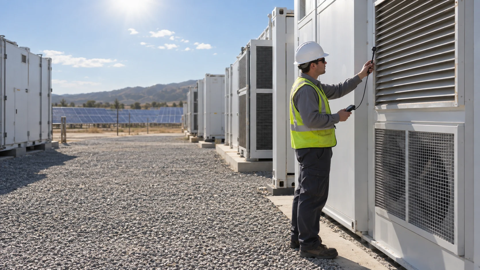
At a tightly arranged BESS site, condenser discharge, inverter exhaust, solar-heated surfaces, walls and low-wind aisles can alter the local air that reaches an intake. The critical input is therefore not only the meteorological ambient value; it is the temperature and condition of the air at the actual heat-exchanger or cabinet inlet during the coincident high-load case. Two enclosures that both pass the same climate data can see intake air differing by 5 to 10 K on the same afternoon.
A recent engineering discussion of BESS heat-island effects describes the same mechanism: warm discharge can be trapped between enclosures, then drawn back into HVAC inlets. Its numerical result belongs to that site geometry, not every project. The transferable lesson is to model or measure local recirculation rather than assume every intake receives undisturbed ambient air.
This article addresses normal thermal management only. It does not define thermal-runaway safety, emergency ventilation, gas detection or the approvals required for those separate system functions.
Air Density Changes the Meaning of a Fan Curve
A fan is a volumetric device, while cooling duty depends on mass flow and heat transfer; density must stay attached to every pressure claim.
Air density falls as temperature rises, roughly in proportion to absolute temperature. Moving from 20 to 50 degrees C cuts density by about 9 percent; adding 1,000 m of altitude takes away roughly another 11 percent. A site that combines both, which describes many desert and highland projects, can ask its fans to work in air about 20 percent thinner than the catalogue test bench assumed.
At lower density a fan moving the same volume of air delivers less mass flow, so the same watts heat that air by a proportionally larger temperature rise. The pressure the fan can generate at a given speed also scales with density, so the operating point slides down the system curve: roughly 9 percent less static pressure at 50 degrees C, before any filter loading. Where the cooling path already includes a coil, filter, louver or tight battery passage, that slide can be the difference between margin and shortfall.
Do not apply one universal temperature or altitude correction to every DC fan. Start with the exact model's test basis, then ask the supplier how the proposed operating temperature, density, voltage, controller speed limit and installed resistance change the available duty. For a preliminary sensible-heat screen, CFM is approximately watts divided by 1.76 times the permitted air temperature rise; a 2,500 W air-side load with a 10 K rise gives about 142 CFM. That is a planning estimate only: it cannot prove coil performance or the pressure left after filters and louvers.

| Condition change | Air density effect | What it does to the fan duty |
|---|---|---|
| 20 to 50 degrees C inlet | about -9 percent | same volume, less mass flow; about 9 percent less pressure at speed |
| plus 1,000 m altitude | about -11 percent more | combined with heat, roughly -20 percent against catalogue basis |
| filter at service loading | system curve rises | operating point moves further toward low flow at the same command |
| fixed Pa alarm on a VFD case | reading follows speed | a warm slow day looks like a dirty filter, or the reverse |
The Fan's Own Parts Have Temperature Ratings Too
Air density is only half of the high-ambient story: the fan's capacitors, winding insulation and bearing grease each carry a temperature rating with its own clock.
Electrolytic capacitors inside the fan's driver age by Arrhenius kinetics: expected life roughly doubles for every 10 K below the rated temperature and halves for every 10 K above it. A capacitor rated 2,000 hours at 105 degrees C reaches about 8,000 hours at 85 degrees C and about 32,000 hours at 65 degrees C, per the Wuertth Elektronik lifetime formulas. The rating is a core temperature, not the air temperature; in a sealed driver running at a 60 degree C inlet, the dielectric can easily sit 20 K hotter than the air, which quietly consumes the margin the datasheet seemed to promise.
Winding insulation is rated by class: B at 130 degrees C, F at 155 degrees C and H at 180 degrees C. The temperature-rise limits in IEC 60034-1 assume a 40 degree C ambient below 1,000 m; above that baseline, each degree of ambient consumes one degree of the allowed rise, and thinner air at altitude cools the motor less. The durable combination is Class F insulation run at Class B rise, which banks about 25 K of margin and roughly doubles insulation life compared with running at the class limit.
Bearing grease completes the set: SKF's sealed-bearing guidance puts grease life at roughly half for every 15 K of operating temperature. Add the three clocks and a fan that is catalogued to 70 degrees C may still be a fan whose electronics, windings and grease all expire early at 60 degrees C with a hot impeller recirculating onto its own intake.
| Part | Rating basis | What high ambient does |
|---|---|---|
| Electrolytic capacitors | core temperature, life halves per +10 K | 60 C air plus driver self-heating can cut rated life by 4x or more |
| Winding insulation | class B 130 / F 155 / H 180 C; rise limits assume 40 C ambient | each degree above 40 C spends one degree of rise budget |
| Bearing grease | life roughly halves per +15 K (SKF guidance) | an 85 C bearing runs its grease clock four times faster than at 55 C |
Interactive: Set the High-Ambient Test Conditions
Switch the conditions to see why several small margins can combine into one weak operating point.
The model is qualitative. It does not calculate a fan curve or battery temperature; it makes the required verification signals visible before an engineer signs off a high-ambient test.
Check Recirculation Before Buying More Fan Speed
More RPM cannot correct an inlet that is repeatedly fed with the system's own hot discharge air.
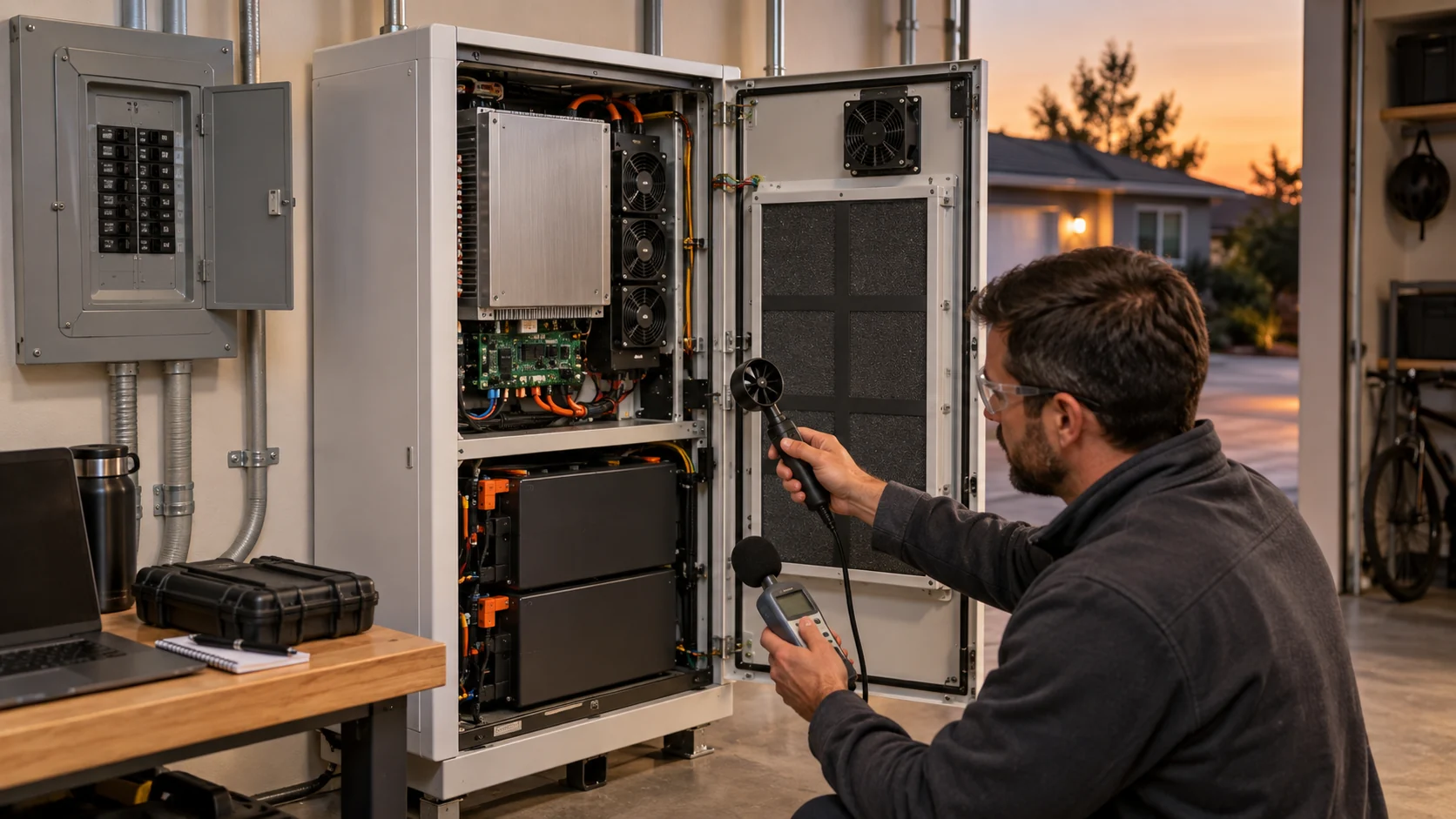
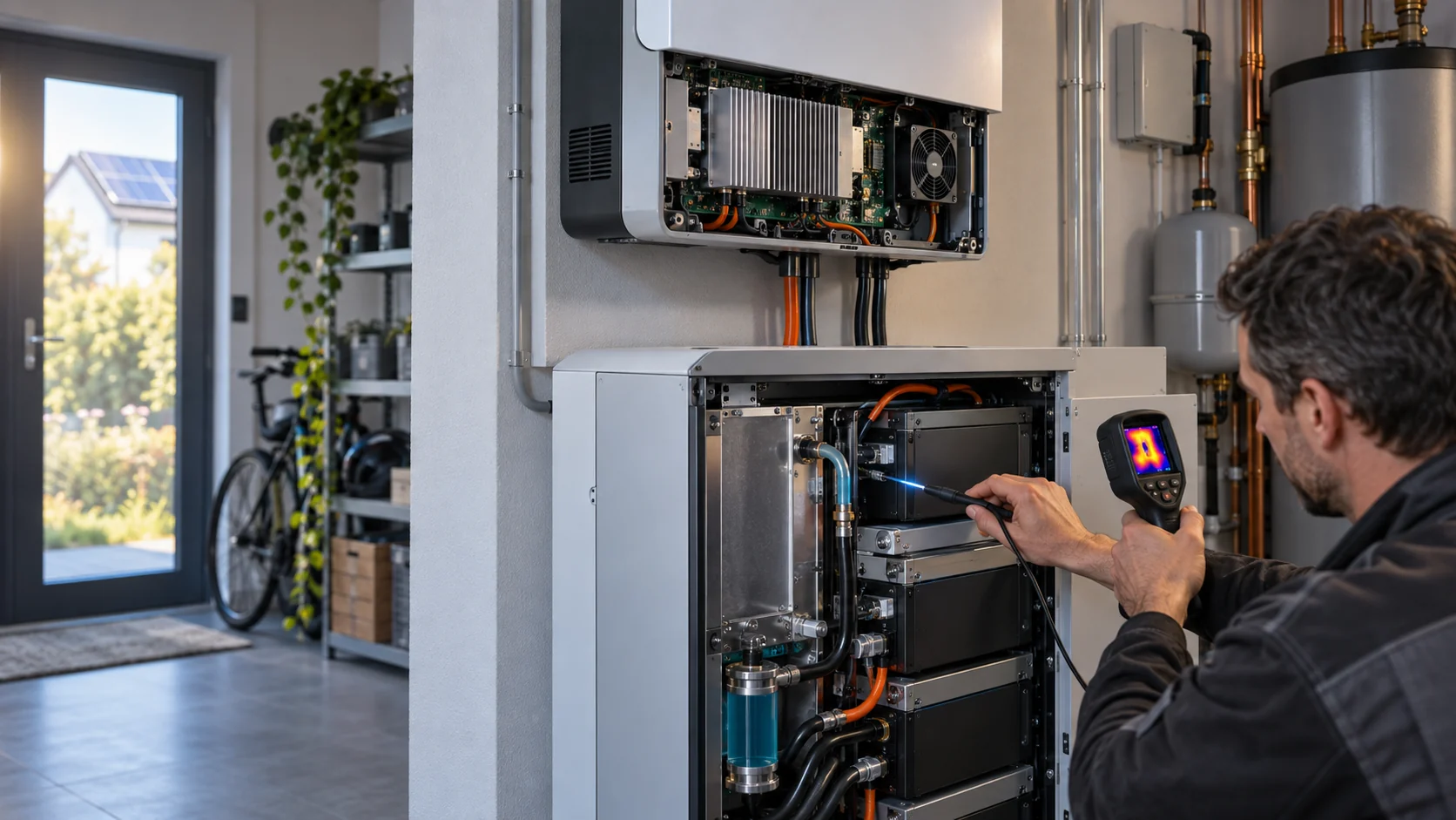
Walk the site during the hot, loaded condition. Identify condenser and equipment discharge directions, nearby intake louvers, prevailing and low-wind conditions, aisle geometry, screens, walls and service clearances. Infrared imaging can reveal hot surfaces, but use an appropriately located air-temperature probe to establish the intake condition; surface temperature is not automatically air temperature. Solar gain belongs in the same walk: a west-facing louver in full afternoon sun can add several degrees to the intake even with perfect site spacing.
If local intake air is elevated, evaluate the site and HVAC geometry first: discharge orientation, intake separation, shielding, louver free area, aisle flow and maintenance access. Any change that adds a guard, screen, duct or baffle must be returned to the installed pressure-drop budget. A recirculation fix that creates excessive restriction can trade one thermal problem for another.
This is why the fan selection must be made after the air path is fixed. AMCA system-effect guidance and the fan/system curve intersection remain the basis: the useful result is airflow at the real high-ambient resistance, not a free-air headline number.
From Climate Data to a Fan Command
A defensible high-ambient selection turns the site's design temperature into a speed command with a stated reserve, not a catalogue headline.
Start from the statistical design temperature for the site, not the record extreme: most cooling specifications use a dry-bulb value that is exceeded only a few hours per year, then add the measured or modeled recirculation and solar allowance on top of it. If the weather file says 43 degrees C and the heat-island walk found 4 K of local rise, the fan's design inlet is 47 degrees C, and that is the number every following calculation uses.
Next, convert the thermal load to an airflow demand at that inlet: the sensible-heat screen above, then the real coil or heat-sink calculation with density attached. Size the fan so the required duty sits comfortably inside its derated curve, and state the reserve explicitly. A common working value is 10 to 15 percent of speed reserve at the design point. Do not confuse that reserve with free capacity: fan power follows roughly the cube of speed, so a +20 percent speed intervention costs about 73 percent more electrical power, plus extra heat the fan must then move.
Finally, cap the command. Many DC fans accept a maximum PWM command well above the speed their installation can usefully sustain; setting a firmware speed limit at the validated maximum protects windings and electronics from running into a region nobody tested.
What to Ask Any Fan Supplier at 55 Degrees C
High-ambient duty is a supplier conversation, not a catalogue lookup. The answers are what separate a rated fan from a suitable one.
Ask for curves with the test density stated, and for the supplier's correction basis at your inlet temperature and altitude rather than a generic percentage. Ask which rating in the datasheet is an air-ambient rating and which is a core-temperature rating; a capacitor or driver spec quoted at 105 degrees C core is not the same promise as 105 degrees C air. Ask for L10 bearing life calculated at your operating temperature and speed, with the assumptions written down, because a life figure without temperature attached is not verifiable.
Ask how the electronics derate above the rated ambient: some drivers reduce allowed speed or current above a threshold temperature, and that limit belongs in the control design, not in a field surprise. Ask what happens at the voltage extremes of your DC bus, at minimum and maximum command, and at cold start after transport. A supplier who answers these five questions with documents is ready to build for the site; one who answers with a catalogue page is selling a part number.
Validate the Worst Coincident Condition, Not the Hottest Number in Isolation
The most revealing test often combines high local inlet temperature, high thermal load and the representative installed air path.
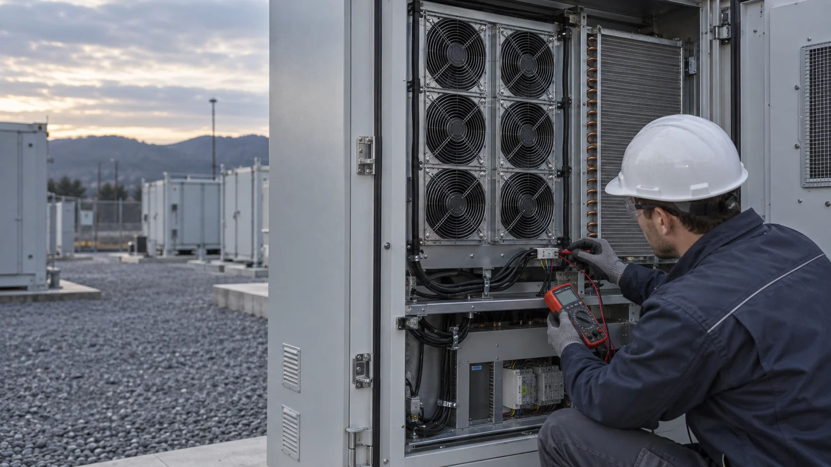
Define the actual allowed operating modes with the BESS and HVAC teams: charging or discharge load, expected solar gain, local inlet temperature, clean and service filter condition, fan control limits and any project-defined degraded state. Then record the thermal response, pressure, fan command/feedback, voltage, current and alarms through the required time window. Commissioning is evidence that the installed system meets its specified design intent, not a generic promise that it will survive every untested extreme.
Trend the same signals in operation so the high-ambient case stays verifiable over the site's life. Speed, current and temperature trends catch a degrading inlet the same way they catch a failing fan, which is why the predictive-maintenance conversation and the high-ambient conversation share a data set.
- Measure inlet air at the actual intake, not only a distant weather station.
- Keep temperature, density, voltage, speed command and filter condition with each airflow-pressure result.
- Check for discharge-to-intake recirculation during the high-load, low-wind condition the site actually experiences.
- Separate normal cooling acceptance from emergency or safety ventilation requirements.
- Validate a custom sample in the representative louver, filter, coil and enclosure path before production release.
Where MEGA Tech Fits
MEGA Tech builds custom DC and EC cooling fans for exactly this kind of condition-defined duty, axial and backward-curved centrifugal, selected by operating point rather than part number.
For a high-ambient BESS project we can supply fans whose curves state the test density, whose L10 life is quoted at your operating temperature with the assumptions attached, and whose electronics are selected for the core temperatures your driver layout actually produces. Where the required operating point sits outside our standard range, we develop a custom fan and deliver working samples for validation on your machine, in your louver, filter and coil path, at your command limits.
To quote quickly we need the airflow and the static pressure at that airflow, the temperature and altitude basis, the voltage range and tolerance, the control interface (PWM frequency, FG or tach feedback, alarm output) and the connector, the installation space, the noise target and the life assumption with its temperature. With those numbers the selection conversation takes days, not weeks.
Our boundary is just as clear: we do not supply HVAC units, liquid cooling loops, controllers or BMS logic, filter media or differential-pressure sensors, and we do not take responsibility for enclosure safety design or emergency ventilation. We make the fan that meets the condition you define, and we put a sample in your machine to prove it.
Recommended Fan Starting Points
These catalogue series may be suitable starting points for this application. Final selection depends on the installed airflow, static pressure, voltage, noise target and operating environment.
Request a sample for validation on your equipment.
Engineer FAQ: BESS Cooling at High Ambient Temperature
These questions keep high-ambient BESS fan selection tied to evidence rather than catalogue endpoints.
Q: Can I select a BESS fan using the weather-station maximum temperature? A: Use it as an input, but also measure or model local intake temperature, recirculation, solar-driven heat and the installed air path at the relevant load condition.
Q: Does higher temperature always reduce fan CFM by a fixed percentage? A: No. The effect depends on density, fan type, voltage, control limit, motor temperature and the system curve. Use the exact model data and an application-specific verification plan.
Q: Does fan RPM prove airflow at high ambient? A: No. RPM proves rotation. Pair it with installed pressure and relevant thermal measurements, especially where filters, coils, louvers or bypass paths are present.
Q: How much speed reserve should a high-ambient fan keep? A: A stated 10 to 15 percent at the design point is a common working value, agreed before commissioning. Remember the power cost: a 20 percent speed rise costs roughly 73 percent more electrical power near cube law.
Q: Is a fan rated 70 degrees C automatically good for a 60 degree C BESS site? A: Not automatically. Check what the rating is measured against: the capacitors and driver care about core temperature, the windings about rise budget above 40 degrees C, and the grease about bearing temperature, each on its own clock.
Q: Does the L10 rating still apply at high temperature? A: Only recalculated. Ask for bearing life at your operating temperature and speed with the assumptions stated; an L10 quoted at 40 degrees C does not carry to a 55 degree C inlet unchanged.
Q: Is a higher-RPM fan the first answer to hot BESS intakes? A: Not necessarily. First correct discharge recirculation and unintended restriction, then evaluate the required airflow-pressure duty, noise, power and fan life under the real operating envelope.
Q: What should a high-ambient custom fan sample prove? A: It should prove the stated working point, electrical and control behavior, and thermal acceptance in the representative air path at the defined inlet, load and service conditions.
Questions for a Design Review
Bring these nine to the review; every one of them should have a number or a document behind it.
- Which temperature is the acceptance input: the weather-station value or the measured intake, and who recorded it?
- What air density, from temperature and altitude, is attached to every fan curve and pressure claim in the package?
- Where do the fan's electronics sit relative to their core-temperature rating during the worst case, not just the air around them?
- What winding rise budget remains after the 40 degree C baseline is exceeded at this site?
- Was discharge-to-intake recirculation measured during the low-wind, high-load condition, and what allowance resulted?
- What clean and service filter pressures were recorded at the same fan command, and are the alarms speed-normalized rather than fixed Pa?
- How much speed reserve remains at the design point, and what does spending it cost in electrical power?
- Which components, capacitors, windings or grease, define the fan's life at this site's temperature, and what is the quoted basis?
- What must the custom fan sample prove, in whose machine, and on what recorded acceptance points, before release?